Contents
SAFETY
INSTRUCTIONS
REFERENCE
ILLUSTRATIONS.
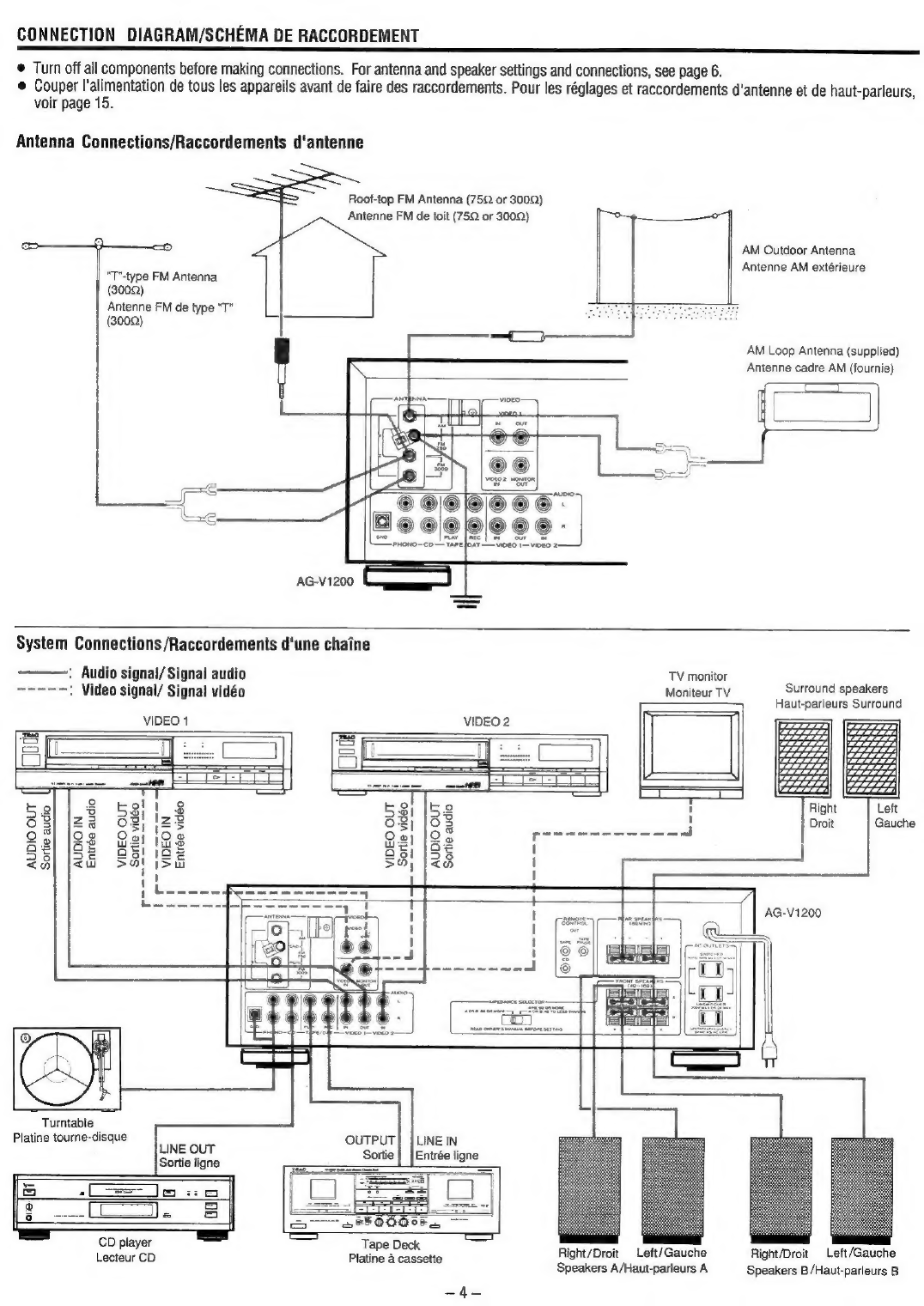
CONNECTION
DIAGRAM..
PRECAUTIONG.............
ANTENNAS
AND
SPEAKERS.
OPERATIONS.........c..ceesseee
Simplified
Operating
Procedure...
Listening
to
Radio
Broadcasts
Tuning
Methods.
Auto
Tuning.
Manual
Tuning..
Direct
Tunin
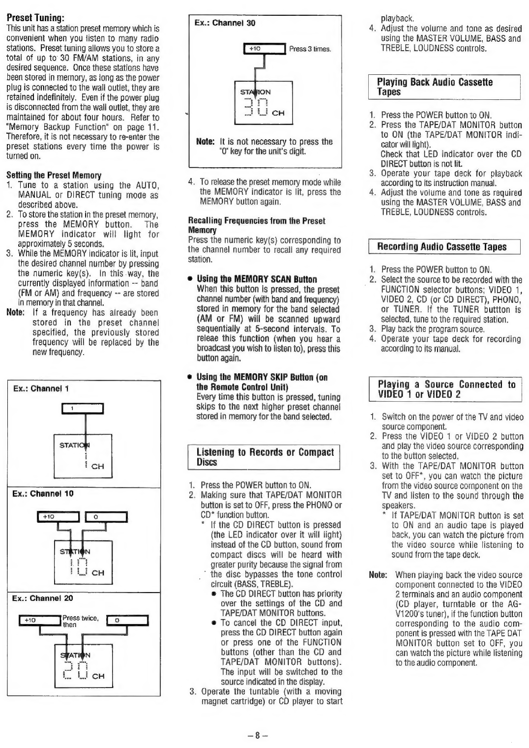
Preset
Tuning..
Listening
to
Records
or
Compact
Discs
....
Playing
Back
Audio
Cas.
TAD
OS
ieacseisrasermtercmiaateetauess
8
Recording
Audio
Cassette
Tapes......
8
Playing
a
Source
Connected
to
VIDEO
1
or
VIDEO
2...
Recording
with
VIDEO
1.
Dubbing
from
VIDEO
2
to
VIDEO
cvcssssssvevecrsateovernewor
sess
9
S.A.V.E.
(Secondary
Audio
Video
Editing)
SYSTEM
Function
~
Using
the
Surround
Effect...
Available
Surround
Modes
Placing
the
Speakers...
Listening
to
Surround
So
Adjusting
Delay
Time...
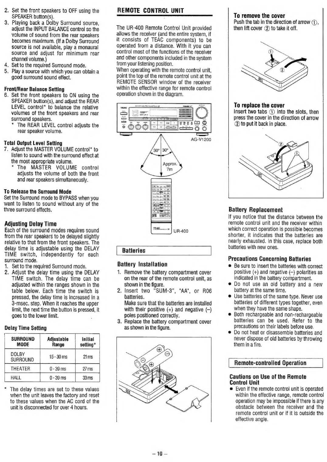
REMOTE
CONTROL
UNIT.
MEMORY
BACKUP
FUNCTION.
SOURCE
SIGNALS
OUTPUT
TO
OUTPUT
TERMINALS/
BLOCK
DIAGRAM..
SPECIFICATIONS...
ONNNNNNN
OO
Rw
c
es
POWER
Button
REMOTE
SENSOR
Infrared
Signal
Reception
Window
DELAY
TIME
Switch
SURROUND
MODE
Button(s)
Multi-Function
Display
Window
TAPE
MONITOR
AUTO
TUNED
STEREO
EMORY
Surround
Mode
Indicators
Band
Indicators
Function
mode/Frequency
display
Frequency
Unit
Indicators
Delay
Time
Display
Preset
Channel
Display
Numeric
keys
MEMORY
Button
CD
DIRECT
Button
ASTER
VOLUME
Control
(VOLUME
DOWN/UP
Button)
©
6O
06
=)
QO0@0E
i)
O99O5508
INPUT
BALANCE
Control
MEMORY
SKIP
Button
@
BALANCE
Control
@
SPEAKERS
Select
Button
@
PHONES
Jack
@®
BASS
and
TREBLE
Controls
@
LOUDNESS
Control
@®
FUNCTION
Selector
Buttons
@
AMM
Selector
Buttons
@
AUTO/MANU
TUNING
Button
@®
DIRECT
TUNING
Button
@
TUNING
UP/DOWN
Buttons
@
MEMORY
SCAN
Button
@
FM
MODE
Button
@
REAR
LEVEL
Control
®
®
only
®
MUTING
Button
only
PRECAUTIONS
Placement
of
the
Unit
As
the
unit
incorporates
a
powerful
amplifier,
heat
is
radiated
from
the
back
and
top
of
the
unit;
the
location
where
the
unit
is
installed
should
be
well
ventilated.
Avoid
installing
where
it
would
be
exposed
to
high
temperatures,
direct
sunlight,
high
humidity
and
dust.
If
the
wiring
is
too
long,
particularly
the
speaker
cables,
it
may
result
in
degraded
sound.
Keep
the
connection
cables
as
short
as
possible.
For
U.S.A
TO
THE
USER
This
equipment
has
been
tested
and
found
to
comply
with
the
limits
for
a
Class
B
digital
device,
pursuant
to
Part
15
of
the
FCC
Rules.
These
limits
are
design-
ed
to
provide
reasonable
protection
against
interference
in
a
residential
area.
This
device
generates
and
uses
radio
frequency
energy
and
if
not
installed
and
used
in
accordance
with
the
instructions,
it
may
cause
inter-
ference
to
radio
or
TV
reception.
If
this
unit
does
cause
interference
with
TV
or
radio
reception
you
can
try
to
correct
the
interference
by
one
or
more
of
the
following
measures:
a)
Reortent
or
relocate
the
receiving
antenna.
b)
Increase
the
separation
between
the
equipment
and
the
receiver.
c)
Plug
the
equipment
into
a
different
outlet
so
that
it
is
not
on
the
same
Circuit
as
the
receiver.
If
necessary,
consult
the
dealer
or
an
experienced
radio/TV
technician
for
additional
suggestions.
CAUTION
Changes
or
modifications
to
this
equip-
ment
not
expressly
approved
by
TEAC
CORPORATION
for
compliance
could
void
the
user's
authority
to
operate
this
equipment.
For
CANADA
THIS
DIGITAL
APPARATUS
DOES
NOT
EXCEED
THE
CLASS
B
LIMITS
FOR
RADIO
NOISE
EMISSIONS
FROM
DIG-
ITAL
APPARATUS
AS
SET
OUT
IN
THE
RADIO
INTERFERENCE
REGULA-
TIONS
OF
THE
CANADIAN
DEPART-
MENT
OF
COMMUNICATIONS.
CAUTION:
To
prevent
electric
shocks,
do
not
use
this
(polarized)
plug
with
an
extension
cord,
receptacle
or
other
Outlet
unless
the
blades
can
be
fully
inserted,
to
prevent
blade
exposure.
-—For
the
United
Kingdom
IMPORTANT
The
wiers
in
this
mains
lead
are
coloured
in
accordance
with
the
following
code:
BLUE;
NEUTRAL
BROWN:
LIVE
As
the
colours
of
the
wires
in
the
mains
lead
of
this
apparatus
may
not
correspond
with
the
coloured
markings
identifying
the
terminals
in
your
plug,
proceed
as
follows:
The
wire
which
is
coloured
BLUE
must
be
connected
to
the
terminal
which
is
marked
with
the
letter
N
or
coloured
BLACK.
The
wire
which
is
coloured
BROWN
must
be
connected
to
the
terminal
which
is
marked
with
the
letter
L
or
coloured
RED.
In
the
U.K.,
this
unit
is
sold
without
an
AC
plug.
THE
APPLIANCE
CONFORMS
WITH
EEC
DIRECTIVE
87/308/EEC
RE-
GARDING
INTERFERENCE
SUPPRES-
SION.
CONFORME
AL
D.M.
13
APRILE
1989
DIRETTIVA
CEE/87/308.