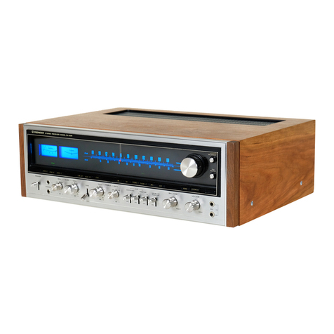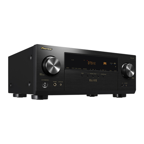
FEATURES
FET-EOUIPPED FM FRONT END
The MOS type FETs in the 2-stage FlVl RF amplifier result
in excellent sensitivity, selectivity, signal'to-noise ratio and
a remarkable f reedom f rom cross'modulation distortion and
spu rious noise.
ADVANCED FM TUNER AND STEREO SEPA-
RATION CIRCUITS
The FM lF stage is equipped with three lCs (integrated
circuits) and an equal number of solid state ceramic filters
for stable operation and maximum selectivity. The FM MPX
decoder operates according to the highly accurate time
switching principle and is provided with an integrated cir-
cuit. The 38kHz MPX switching frequency is sharply sup-
pressed by an effective LC/RC complex filter circuit.
EFFECTIVE FM MUTING SWITCH
Unwanted, irritating inter-station noise on FM is eliminated
by the FM MUTING switch. This circuit, equipped with an
FET, also cuts out useless, too-weak FM station signals,
leaving only strong stations in high-quality reception.
AM TUNER WITH SENSITIVE FERRITE AN-
TENNA
To provide high reception sensitivity on AM. too, a ferrite
loopstick antenna and a tuned RF amplifier circuit are pro-
v ided.
PRECISION-ENGINEERED OCL AMPLI FIER
The audio amplifier is characterized by its extremely wide
frequency response, its great power bandwidth, its low dis-
tortion figures and superb signal-to-noise ratio. lt is exclu-
sively equipped with low-noise silicon transistors. All power
amplification stages are directly coupled, the output stage
is OCL and the power supply is a balanced positive-nega-
LINE VOLTAGE AND FUSE
The SX-828 is available in two models: one model
operates only on 720V, and the other does on one
of the five line voltages, 110V, 120V, 130V, 220V
and 240Y.If your SX-828 is the latter model, set
the unit to the proper line voltage by following the
procedure described below.
CHANGING LINE VOLTAGE SETTING AND
FUSE
To remove the fuse, turn the fuse cap located on
the line voltage seiector in the direction of the
arrow.
Then remove the fuse plug from the unit. Put the
fuse plug back so that the proper line voltage mark-
ing can be seen through the cut in the edge of the
plug. Whenever the position of the selector is
tive type. Loudspeakers and output transistors are protected
against shortcircuits by a fully electronic sensing circuit with
relay.
FULL CHOICE OF PROGRAM SOURCES
All standard program sources can be corinected, including
two turntables, two tape decks, and an auxiliary sound
source as well as two microphones. Low-output MC-type
phono cartridges can be used with the help of an optional
Pioneer step-up transformer which can be plugged in.
TAPE-TO-TAPE DUPLICATING POSSIBLE
With the help of two (open reel or cassette) tape decks,
copies of tapes can be made easily.
UP TO THREE PAIRS OF LOUDSPEAKERS
For easy comparison of speaker systems, or for main/remote
speaker installations, up to three pairs of speakers can be
connected and operated individually or A+8, A+C.
VERSATILE AUXILIARY CI RCUITS
These include click-stop tone controls, low and high f ilters
for reducing noise, a loudness switch for more natural
frequency response at low volume levels, a 5-position mode
switch, a dimmer switch controlling the front panel illumi-
nation, and signal strength and tuning meters for easy tuning.
PRACTICAL AND AT THE SAME TIME ELE-
GANT DESIGN
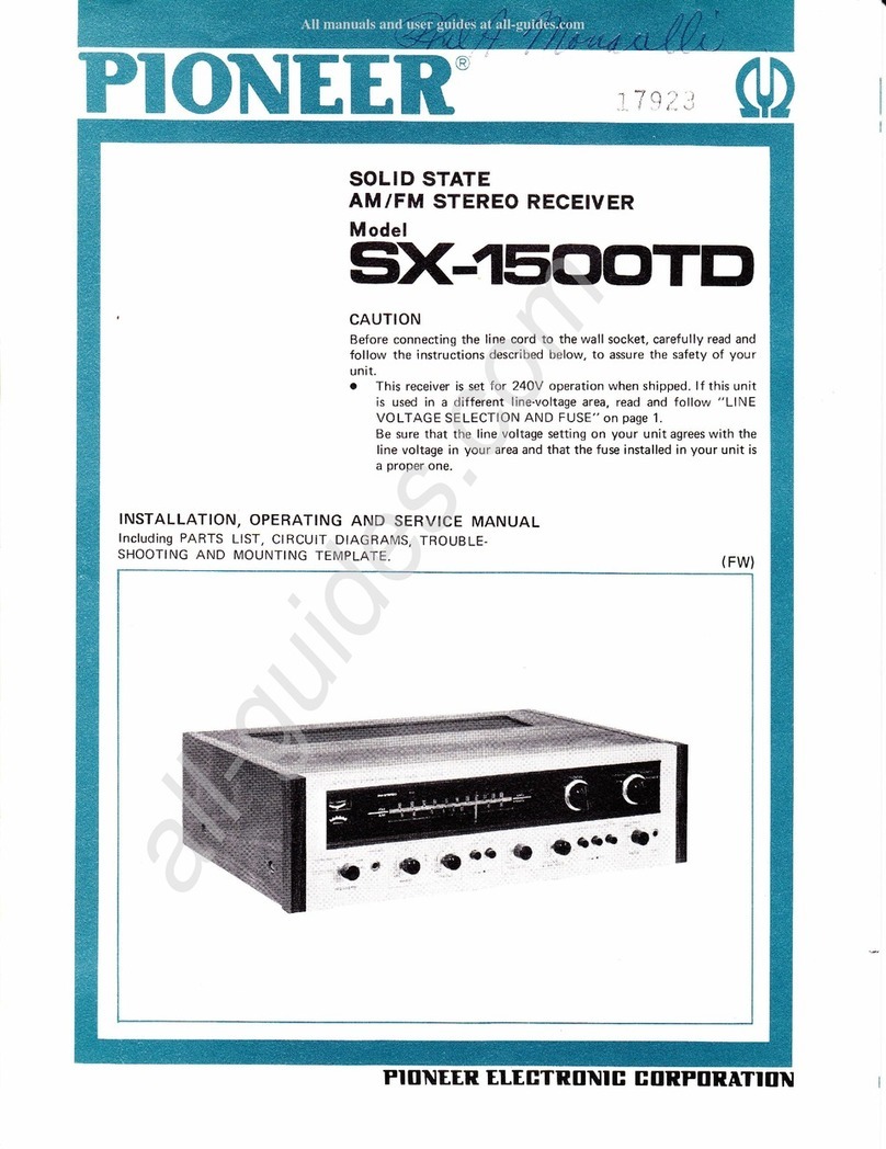
With an exceptionally long and linear frequency dial for
easy tuning. Easy, perfect tuning with signal strength meter
and center zero meter. Slightly slanted front panel for easier
dial reading. Plus the incomparable Pioneer elegance of
harmoniously matched metal , black and natural wood.
changed, check the rating of the fuse. A 1.5A fuse
is to be used for either 22OY or 240V operation
and a 3A fuse for 110V, 120V or 130V operation.
If the rating of the fuse is correct, replace cap.
FUSE REPLACEMENT
When the fuse blows, remove the fuse cap and re-
place the fuse with a new one. See Fig. 1.
{6e'
\.N,i{\
,.€?wtfo
\.&.\F I
,-qw'\t?o
\.&. ts I
.5V, socKEr
dii". "'J"'o
,:*l "^"'"" Fig. 1
