manuals.online logo
Brands
  1. Home
  2. •
  3. Brands
  4. •
  5. Pioneer
  6. •
  7. Stereo Receiver
  8. •
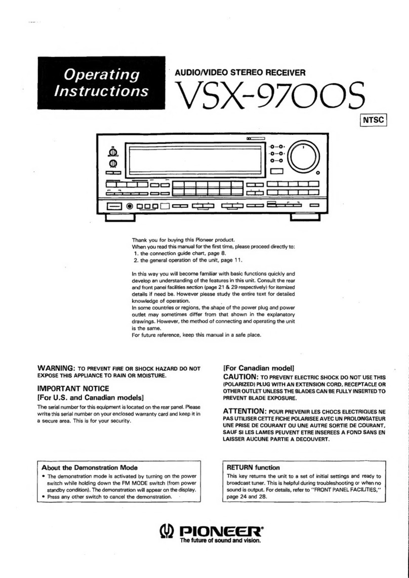
  9. Pioneer VSX-411S User manual

Pioneer VSX-411S User manual

AUDIO/VIDEO
STEREO
RECEIVER
X=-4
11S...
VS
X=4O
luc.
KUC/CA
Q)
PIONEER
The
Art
of
Entertainment
Service
PAZ
ETIET
@
Refer
to
the
service
manual
ARP2O60
for
VSX
—
3700S/KUC.
@
This
manual
is
applicable
to
VSX
~
411S/KUC/CA,
VSX
—
401/KUC
and
VSX
-
401/KUC/CA,
@
The
“
$”
at
the
end
of
the
model
number
indicates
that
the
a
programable
remote
control
unit
is
supplied.
ORDER
NO.
ARP2436
NOTE
1.RESISTORS:
Indicated
in
f.1/44
1/8,
+
5%
tolerance
unless
otherwise
noted
ki
kN
M:MQ,
(F):+41%,
(G):
2%,
(WK):
410%,
MM
:+20%K
tolerance.
:Indicates
a
chip
resistor.
2.
CAPACITORS:
Indicated
in
capacity
(uF)
/voltage
(VY)
unless
otherwise
noed:
pF
Indication
without
voltage
is
SOV
except
electrolytic
capacitor.
:Indicates
a
chip
capacitor.
i
i)
:Indicates
a
chip
transistor.
:Indicates
a
chip
dlode.
—_L
c1
O
BATTERY
=
4004/6.
3V
O
+
T1
Cc&
ne
+,
.10#/16V
0.01
0.01
10k
co
C4
100
oO
T2
6
°
Tpe.
fe
—
2M
OO
O
cs
100p
64
62/61
57|S6jssis4is
3/52
TOTES
Sega?
51
oe
ee
ed
1\pp
©
s%
§ x
VF
e
>
a
&
Ww
stop
|“?
O
|
os
4
|
3
ame.
}-48
ma
ca
ile
Shae
2
px|
2
wae
p7_
8],
Leal
1
144
;
faz
-
=
Caer
eeea
tT
Al
410
42
KO7
oe
Paz
aa
|
CPU
‘ka
we
A2
11
2
as
2
41
KO6E
ei
"
40
KOS
sO
|
32
Ko#
At
CE
1
|
PE
3
as
15
|
1s
fo
37
KO2
A7T_16
45
1
P3e
KO1
5
:
AB_17
45
a
9
P25
KOO
;
a
34
K17
*
A
bs
2)33
KIS
KIS
(
K14
1C1
PDGOS3-A
a
4
1C2
AZC1232
OE
K13
-
t
22k
H
a1
AZC1229
'
\
Q2
AZC1230
ae
aE
K12
Q3
AZC1231
D2
AZC1224
‘
KI
D4
AZC1225
DS
AZC1226
KIO
to
D10
AZC1227
Bea
D6—-DY,
AZC1228
011
jess
otherwise
noted
kik,
20%
tolerance.
SS
otherwise
noed:
pF
tlectrolytic
capacitor.
C6
16V
0.01
tes
1
6
O
O
51
REF
oe
8
<
n
>
[+
@
jw
O
3.OTHERS:
em
-Signa!
route.
FG
:Adjusting
point.
The
mark
found
on
some
component
parts
importance
of
the
safety
factor
of
the
part.
Therefore,
when
replacing,
be
sure
of
use
parts
of
Identical
designation.
*%
marked
capacitors
and
resistors
have
parts
numbers.
This
is
the
basic
schematic
diagram
but the
actual
circuit
may
vary
due
to
improvements
In
design.
c2
|
dp
100K
76.
3V
R4
+
=
680
Q2
S$-8052
ALO
©
ive)
yn
MP
1
od
Cy
a
ene:
an
ya?
a
ae
33k
4.7k
3
|
2448
ne
1
p44
ve
na
ibeer
"02.
Sak
fs)
3)42
KO7
j|
2
:
0
3
1|
2
:
Z
S
$39
2
9 p
p
9 S © e p
42
sé
[s14]s221]830]s38]
s46]
554]
se2
KIS
O13
$06
p10
Ae
eh 4d
ok
ok ee oe
;
$29
|
$37]
$45|D53|
S61
KI4
soete
D11
Se
x
x
x
x
os
$28
os
av
ee
DS
Sw4
K13
A
- e
o
o
pa
Sw3
KI2
s2
|si1o0|siB
gs
ee
$50]
S58
KI
Kt}
Xo
a
Z|
x
si
|s9
a
Ze
ee
p10
2
0
K10
swi
7?
172
x
p
KSO
OT4
VSX-411S
The
underline
indicates
the
switch
position
SW1:
AUDIO/V1DEO
SR
RECALL/USE/LEARN
SW3:SR
RECALL/USE
SW4:
USE/LEARN
MEMORY
CLEAR
SS:
ON/OFF
CENTER/REAR
S6
:
ON/OFF
RESET
RST:
ON/OFF
TAPE/VCR
S2:TAPE
SELECT/ANT
$10:8/8
S8
:
b>
see
S6:easea
S7:
bsp
$9:
<
$15:1/VCR
CH-
$16:2/VCR
CH+
$1:
VCR
POWER
$12:@0/@
$3:
1/8
cD/VOP
$13:
DI1SC-SELECT/DI
SPLAY
S$14:3/8
$11
:eet7
SEARHCH
S20:
wav
CHAP/FR-T
IME
S21:
b>
/
De
SS:
«ase
S22:
>/>
S35:a/i
$17:CD
POWER/VDP
POWER
$18:
PGM
$193:CD4+10
TUNER/TV
(CD/VDP)
$24:1
(1)
$25:
2
(2)
$26:
3
(3)
S27:
4
(4)
$23:5
(5)
$29:
6
(6)
$30:7(7)
$31:
8
(8)
$32:3(9)
$28:0/10
(0/10)
$34:11
(MEMORY)
$36:
12
(CLR)
$33:
STAT
J
ON+/TV—-CH+
$37:
STAT
]
ON-/TV—-CH-—
$41:
BAND/DUAL
$52:DIRECT
ACCESS/TV—-FUNC
$53:
FREQUENCY+/TV—-VOL+
$43:
FREQUENCY-—/TV—-VOL—
$59:
SCAN/TV-D1SP
$42:HITS
$54:CUSTOM
MEMORY/CH-RETURN
$40:
TV-POWER
AMP
/AMP
SSO
+:
VOLUME+
SS1
=
VOLUME
-—
$58:VDP
S$63:VCR
S64
:MUTING
$48
:RECEIVER
POWER
S57
:TAPE2
S47
:SURROUND
MODE
SS6
‘SURROUND
LEVEL+
SS5:SURROUND
LEVEL-—
S61
:TUNER
S46
:SLEEP
$60
:CD
$62
:
PHONO
S4:TAPE1
$49:LINE
S45:VIDEO
SIGNAL
SELECT
S38:DELAY
TIME
$39
RETURN
S$44:S]IMULATED
STEREO
VSX-411S/VSX-401
3.
SCHEMATIC
AND
P.
C.
BOARD
DIAGRAM
To
COMPLEX
assembly
|
CONTROL
assembly
(AWZ73514)
J3
:
TUNES
mnt
rot
VR317
|
VAII8
RSIS
ATA
VALS
WAI
co
wa0t
AAV
1096
et
(Ger
ae
bl
meneS
088
8.18
y
Gu
GIO
GS
|
Pre
at
oP
c3a7(}
casa
C329
C328
c321
a
oe
ica
mee
el
ns
sm
de
a
a
ee
ae
=
=
ha
Ma
hil
nH
ay
(a
cu
be
wszeee
{1
a
a
[a
~—
PANCAN
ZA
ANCA
jo}
—
fos
JAY
N
J
ah
=
PAL
rt
sTuD
———*#
vv
ate
t
MUTING
ola]
:
“fhe
ok
|
Twicea
7)
simuareo
StS
fof
no
;
Tete
‘erence
|
SUF
ae
a=
G4
C=}
fa)
Fie)
fT
lel
[222
Lo)
{caeef[o]
ry
oa
“y
-
o
e
To
MOTOR
VOL
assemoly
=
on
a
3
BOEESEEE
1
CNB
PT
ots
FY
Tires
io0-02
an
|
Paso
ee
9
fe
=
—
fe
7
eile
if
aaa
7
—
i
ae
—
Ss
=
7
100/76
|
0.41
A407?
4vk
na
nara!
fe
Da
i
Ae
33a
ge
4709
s200p
|
[2700p|
[Baocdp
-018
7
Sie
tate
i
a
Tenis
rT
Ty
yy
©
TT
|
li
|
|
|
|
|
|
oT
|
To
COMPLEX
assemoly
To
COMPLEX
assembly
J2
J4
1.
RESISTORS:
SWITCHES:
Indicated
in
2,
%W,
“eW.
+5%
tolerance
unless
otherwise
noted
k
:kQ,
M
>
M&,
(F)
:
+1%,
(G)
:
+2%,
(K)
:
+
10%
(M);
+20%
tolerance
SP
SWITCH
asseably
S570
SP
A
ON-OFF
/
SP-B
ON-OFF
2.
CAPACITORS:
CONTROL
sere
:
Indicated
in
capacity
(uF}/voltage
(V)
unless
otherwise
noted
p
:
pF
S401
0
U
S421
TAPE2
Indication
without
voltage
is
SOV
except
electrolytic
capacitor.
Sate
SHEN
DONE
pier
30
$403
2°
$423
9
$404
1
S424
8
3.
VOLTAGE,
CURRENT:
S405
FM
S425
MUTE
:
Signal
voltage
at
(
100
W+
100
W
8s2)output
(1kHz)
S406
AM
S426
7
__]
:
OC
voitage
(V)
at
no
input
signal
S407
MEMORY
$427
6
Value
in(
}
ts
DC
voltage
at
rated
power.
S408
MEMORY
SCAN
$428
5
<=
mA:
OC
current
at
no
input
signal
$409
POP
S429
4
S410
ROCK
S430
3
4.
OTHERS:
S41.
OTHER
S431
RETURN
eiereal
route:
S412
HITS
$432
V-SFI.
Rida
sian
$413
CD
S433
POWER
@
:
Adjusting
point.
a
;
ot
S414
TUNER
$434
S.S
e
A
mark
found
on
some
component
parts
indicates
the
im-
S415
PHONO
$435
DOLBY
portance
of
the
safety
factor
of
the
part.
Therefore,
when
replacing,
~
S416
AUTO/MONO
S436
SIM.
be
sure
to
use
parts
of
identical
designation.
S417
AUTO/MANUAL
$437
STUDIO
A
marked
capacitors
and
resistors
have
parts
numbers.
S418
DIRECT
ACCESS
S438
SURR.
S419
VDP
S439
DELAY
TIME
This
is
the
basic
schematic
diagram,
but
the
actual
circuit
may
vary
S420
VCR/TAPE}
due
to
improvements
in
design.
Go
GB
G?
G6
eas
65
Gel2/2)
a
(NT
(TN
=
RE
a
I
(20
WAN
VXI
©
\afereReoy
(eka)
PPG
Bd
BB
cas)
|
zs
—
n
w
wo
z
»
Ss
eeeeceessceeeoes
=
eae
:
—__
__
.
-§
___
TT
---
0
ae
MEMORY!
APE
2
|
STUDIO
|
SIMULATED
REAR
LEVEL]
MEMORY!
STATION
7
PECAY
TIME]
|(ca@EAACH
|
Bs
+2
3
a
rEweet
2
ara
vee,
EE
i)
ak
uring
}
HO
foocsy
SURROUND]
(SNTUT
a
Pores
25
ABATED
=
|
oa,
em,
EO
a
-_
=
isa
63
TEeREO
|?
BURRAGUND
MODE
-)
ret
a
|
Fae
TUNING
|
at
Pa
to
Ss?
E€2
Teno!
(F
ic
ro
|
HUNG
|
aE)
a
Ga
7”
G3
G2ti/2)
Gl
pe
:
isa
fs
dT
3|
3
“
si:
stereo
|
Ske
See
eRe
elie
BSSaseasee
160
TUNER MUTE]
Pe
ee
tt
tf
4
Haeh
eb
S
pees
6
ti
hoe
ak
er
Ro
ey
eect
eee
Se
i
Bi
cao?
C408
a.
047
0.047
C404
0.601
aaa
:
ef
4
3
fe
C408
0.047
i
340
Fin
i
rE
841
a
gs
agsempDly
JS4
NN
;
=
w
>
=
©
“
~
yo
~
x
>
AxN1010
Pa
ye
pcs
es
1
9
zl
dl
*
To
VIDEO/SURA
assembly
CN9
c168
4700
2
SEAIAL
FE
MODULE
ASSEMBLY
4xQ1002
-
x
zg
w 3
3S
.
alt
a
r
“s
a
»
COMPLEX
assembly
(AwZ2987)
vnge
TMETER
gy
2
24
art
2
a
hes
ci02
0.
1/25
AE
Atos
3p
c105
10%
0.022
Faat
atF-208
os
-
tow
jag
C32:
Sy
2hlis
Arisiaizs
22000
Riz2
6.ak
0.047
0113
ae
am
k
1
+h
c122
0115
HSS
104-05,
O114
SJMS5
104-02
Wooo
S
L311
aTE-079
i
+4
a
e131
45391005
cis 132
150
|
iso
t
#
x30
0.04
ro:
(To
page
3g)
To
36
<
_—_O-
—
PLAY
ee
TAPE
2
4
ms
aE
1
¢
pn
2.
2k
—
PLay
waar]
nets
VCR/TAPE
1
1M
330
Tea
eure
aw
L__
REC
vor
S
¢
rez0112/2)
NUM45580
XP
C233
T
C235
e200p
47/16
c237
24000
1c2s3l2/2!
NuMaS58S-*
C254
4.
7/50|*
1cas3li/2!
NuM4S585-X
q
Ic202
C9164N
202
c201
B
0.047}
|
1/80
c23e
case
C240
nase
3
a
=
Rei2
C232
2
236
cza2
A208
—
+
ole
5
R242
150BV
750k
8
nzie
e201
11/2!
i
Reve
NM
4SSBOXP
C244
voP
150mv7S0K0
A216
—
Rec
|
é
ww
A238
ICASTAPEL
Roos
LL
PLAY
A
220
REC
S
wv
:
nee
TAPE
2!
Aste
Le
aw
J
10a
750K6.
Reee
a
>
=)
Po
a27a
g.
ik
|
C27)
A276
3 2
[o-
98
10K
re
bh
oor
3
Rs05
Tea7.ls/2t
4275
47k
NUM
45S88—*
om
+
C276
cso1|
c272
33000
2.2/50,
o.08
~
¢
8280
6
ik
4.749
$
B71
200k
+
2
csz0
=
100/25
2
9271
HSS
104-2
as
104-02
|
R281
48
a77
ak
1.04
2
o
°
a)
ee
A276
1
oz
188104
“02
nz79
x
¢
a
rs
csoz;
©
La
PS
E\
23
A168
£163
10000
T
1000p
15k
=
*
ata
C164
tk
——
470p
jose
VAISS
@®
apS8104-021
4.
7
MOTOR
VOL
assembly
;
voca
ene
wa]
3.
3fyeo
¥OL_
DOWN
[vu
J
ee
x
a,
ae
i
C971
0.047
|
22000
Wm
54
Aiz2
C122
6.8
0.047
of
ous
we
5104-05,
a
hal"
as
V2
“a
5%
ett
2
=
0a
an
sa
ae
aed
|
2841048
pi,
4
an
Lot
Ld.
Ce
Ae
ne
(RENERRSicicens
eee
gegen
jpg
geen
peepee
Bae
ee
ee
de)
,
e
|
Cn)
)
cn
Of)
eS
Co
eer
Lisliss:0<-od
io-sf)
esi
—
—wv
Ata
Wwe
a
%
cisa
Assi
4.77/38
an
Aisz
,
it
ey
=
—
a
lem
To
18
gl
{To
page
10)
noo
Th
vewo:
To
VIDEO/SUAR
assembly
100p
Jid
any
LT
(To
page
9)
see
ane
:
To
VIDEO/SURA
assembly
cNii
(To
page
10)
i
afi
a3
To
VIDEO/SURR
assembly
cNi3
3
fn)
3}
t
R274
9.1K]
C27)
R276
see
2
[98
10k
+4
0.03
cart
oon
BE
i
Tea7iteval
Numa
S8S—K
:
+,
a
’
t
G27
;
____s4.
289
272
200%
1
:
cc
‘
390 390
pens
‘
11/at
i144)
bend
venice
ie
Ai
$5104-C2
ae
yj
——_—-
2
MSS104
javae
1
77
02
ASA
112
OL
"o.
Le
eno
re
y
i
>
f
cee
0501
e604
3
MZSivad,
2sc24se
“>
wer
oo
ie
|
’
:
om
o-
\
et
Be
g
eases
fat
ee
ee
RECS
iy
t
rere
ah
}
Tcsos2er
(-)
Reis201
UR
|
(2
sete
gS
_w————
———————
«§
i
2
-
©
ee
Se
6
ee
8
s =
=
= s
is
a
4
|
5
1
6
1
|
=e
CONTROL
assembly
(Aawzegs0)
ae
ich
sake
ee
ae,
i
6822
Sse
LOB
233
&
5
*b3e0
eos
C328
ic325
0313
--
:
ee
ie
7
a
SS
oe
JAR
AN
VAN
Crees)
Onn
IO
eige
de
~
ea
ize
“Tat
15393
ole)
[Cole Volo}
[felfel
[Sal
[oI
|,
||
Eee
ame
PUTO
rare
e
Ream
teva,
MEMORY
STATION
rar
anne
Mevor’
-
Peeve]
Fy
yoorsy
summon]
mm,
SAN
I
plete
SSTERSD
*
SURROUND
MODE
-
-2
ne
TUNING
QvAch.
et
O312
aac
HSSi04-02
[eng
or]
C403
|
Cave
100/6
|
9.01
te
l
t
ca0s
0.047
é
s|s/3lzi7
[|
zielielel#|s
3}
a}
a]
2}
2]
#14] S}c]
2]
2
-
5
2
-
6939334
-
ne
To
VIDEQ/SUAR
assembly
(To
page
10)
ta
{To
page
10)
i
CNi2
pe
To
35
¥IDEO/SURA
bp.
SS
:
(To
page
9}.
?
we
weectni
a
(EEE)
DPOB
HG5104-02
—
assemb]
=
=
-
-
=
Tien]
:
x
po
aroe
270
i
R704
270.
R708
ons
an
a
a707
oy
a
aa
cre
#
1
5
acG1003
:
[T4
abiors
"S8104-02
D712
C710
¥c70«
i
4
é 6
yt
4
>
'
—————a
=
CEE)
eeeiedee
HZSEBA|
47/16
|
10/50
aex1002
©
2.2
!
iar
Ee
wme
oF
4
f
:
i
c707
*
R706
‘
0.047/5-5
580
ry
i
P=]
Pt
{|
a
ela
[
tae
ep
—
'
f
p71a
|
0709
=
V/-b--4--
7a
r—O
'
aa
Hss104,
ss
estos
04
aCG1003
5]
ual
—
=
23
=r
=
tO
ta
.
|
ag
Goniae?
-
|
JASR-
122
2
To 19
2
-—{é}-
=
NN,
3
Paya
‘
A756
€
604
sa
eg
tk
sents
oss
I
ba
ANI201
wW
'
weeiea|
9754)
aD
!
“02
{
220k
|
MULTI
°
CA
A752
3
oa
|
7
-
So
L
AEMOTE
°
ta
aj
:
+
——!
c7s2
&
0783
a2
i
=
a
R751
470/28
SS566
!
i
a
S
Pal
4
aTri01s
:
a7s2
by
1
Ie
o752
*
sa
remote
|,
soe
Kerss‘Korss
6}
teres
out
|
2m
47/16
|MZSS8a.
ACG
1005
a
Ge
-
aC
SOCKET
SP
SWITCH
assembly
|
akP1053
7
Sees
ees
ee
—-
es
———e
o
Sincere
ee
—
J
caoa
?
0.047
x2
a1/DaTa
ad
to
VIDEQ/SUAR
assembly
CNg
aa
:
!
4
CREREREXX)
aad
1
tJ
(To
page
9)
it
3
i,
11
>
wy
tal
#E
»
=
¢
8
AXX1010
11
Siac
aT€D
ww
a
C1003
Da00:
10.047
MSS104-0z
WE->
Git
y4slei—
ly
(AWX4045]
aro0:
«
Re203
B
MSS104-0¢
bwos.
D1003
MSS
104-02
w
£1002
ay
0.047
82
a
@
+
;
Cid?
a
ain:
ICAP
a
;
470%
1c10021
1/4!
9
pluena
1c
(3)
10.
12;
De
5
y
83007
©1005
a
arn
o.08
i
R1010
'
10%
!
|
)
Es
a1007
fy)
PN1207
2
1006
‘
miong
|
1203
22%
3
Q1005
2581048
26
12
+63V
sa
issa)
47
1874)
a
cs31
100/10
|
|62.
6!
0353
100
4.7
RS61
|
10
PROTECT
POS.
1€88
7g)
[A
11/4)
9.
aax2
S
1
TO
SPEAKER
R513
R515
11/4)
(i/al
-638V
R562
TO
SPEAKER
TO
PROTECT
+63V
S.8
AUDIO
OUTPUT
+63V
cSs3t
100/10
|
|62.6|
TO
PROTECT
TO
SPEAKER
R513
R315
(1/4)
(i/al
-63V
TO
SPEAKER
TO
PROTECT
+63V
4
B
+o)
@
6
|
poLey
Pence
Tc
COMPLEX
assembly
413
{
Te
-
oa
=
eer
ees
oC
=r
-
o
37
Q
—_———
—
VIDEO
SURR
assembly
(AWZ2922)
iS
'
<a
ceo
“15
:
a3
cui
p
:
‘
b
Pata
fee
ae
KPCa
[ZI
ia,
Camas
R840
©
CB40
,
~yete
se]
Po
;
Y
10l1/4)
9.047
~
uw
3
et
'
}
:
Rea
5
ipa
Aor
Meng
RS
RA42
:
So
;
Joc
MUTE
=
14)
Bo:
7a
os.
VIDEO
cB08
47/10
ake
:
—
yt
Aes
1
AYBaC
(fe
om
LT
ca07
47/10
peel
>
ABaa
VDP
g
10011/4)
RB2z0
D840
MONITOR
Q
ie
!
resest2/2!
5 8
Agi4
ry
Ag13
2e<
3
O
To
F
2eK
agis
:
Rai2
22
Ro17
(To
page
23)
[I
100
2
;
Se
oe
=
ee
6.
8k
=
a
tae
aaa
eee
a
ame
8
4.
7/80
1¢9081172}
oe
Csi
ok
eB,
6.0
Sees
1
ee
ee
p<]
«K
wo
STigitsa?
Hil
ii
Ts
CONTROL
assembly
eae
J9
Lf}
[
cg23a)
aoa
:
nae
ee)
sear
a
‘
CNI2
yKPCS
[|
ee
ed
sev
ea
i
CE
7
Se
eG
|
pe
|
|
ee
PERRET
p=
42
4°
£3
BB
oe
OG
OB
ese
|
a
To
COMPLEX
assembly
J12
(To
page
25)
»
DI
VS.
RAS38
1061/4)
Ag24
4.
1%
+
+
‘
C:
ae
220/10
cece
cg:4
1000/6
|0.087/28
9
,“|-
~~
Ag25'
6
Aga
>
-
am
wp
C944
47/25
8
a
id
prcoa3)
hcsaz
100/16
“F
27/16
To
COMPLEX
assembly
Jit
(To
page
25)'
aS
fea
ol
=a
0)
=
LEX
assembly
J13
(To
page
24)
=
bend
=
ee
-=
Es,
=
og
@)
IC870
UPC1270H
0871.
67
HSS104-02
;
©|>
pea
REAR
AMP
assembly
oer)
2
1SS104
SSS
p-
SPE
AKEA
Qs?
i
2502240
os
re
PCO
YAR
9870
2SC2458
i
eecss
©
pers
im
[ia]
[25.7]
a
Ra40
=
C840
Aa70
1014/4]
0.047
re
ik
$$$
40
Gyas
vise
ca70
ca7:
|\aasz2
7aH
1
REAR
IN
4
=
2.
2/50
1000p
GMO
i
"T—
oven
cod
1]
ee
mes
ncaa
_{°T
|
ce7e2
AB73
100/10
330
be
F)
ye
=
a
ae
=
Ee
aoe
7S
oe
=
EEE
erste
psy
Ly
ed
ae
ers
Vii
CN
I
I
a
.
OF
a905
Ag16
(Dy
v10
1.
2k
@:
pes
|
REAR
OUT
of
REAR
IN
|
|
R917
oT
eno)
1.
Sk
CT,
R916
6.
Bk
B
1c904
BU4066BL
Icg903
LA2730
Ic90e2
M50198P
Ic8o1
NJM2253S
To
MOTOR
VOL
assembly
C905:
1C906
NUM4558DXP
J40
Ics01
TC9154AP
IC860
UPC79M
12H
»
(To
page
24)
QB41
AN1201
Q807.
903.
904.906
AN1203
Q9301-
902
AN2203
Fo
Satie
ath
ES
ag,
St
eee
ee
aec3:
806
2541048
MAIN
SIGNAL
aso5
25C1740S
0601.
802.
804.805
25C2458
Q8o8
25C2878
‘
gh
ein
cet
ces
JN
\
REAR
SIGNAL
4
0801-803.
840.
841.
HSS104-02
Q901-
304-907
D864
HZSSALL
co
gee
idem
0860-863
10E2F0
AM
SIGNAL
«a
=
wz
WS
dy
0OgSté«éS
g
B=
Ga
68
r-t-4
fetal
aé
2.3
4
§
6
7
8
39
40
4
ee
_
2m
A
ie!
Ip
©
ee
C
fj
'
a
f
tre
gee
Belo
i
1
ye,
©
016
&
MHZ
5
3s
—o
To
O
Ce
|
J
cs23
470p
NEKO
page
25)
‘
Ag42
620
i
A935
1
2k
C934
22/16
Fa]
+
KPCIECN14
eer
is
lac
ReaR
cecol_
1
Tene
bro:
[OT
one
+)
ies
|
ee.
ee,
7
aa
oS
phe
A937
AB
)
ng
1
470l
ow
re
‘
J14
ner
cess
(To
page
26)
4701174)
ICoe0
sls
Ag39
270k
aoe
¥OUT
]
VIN
D
AR21
po
howe
pre
Pg45
C941
<7
6.2%
T
0.033
.
C940
cg39
C938
e931
J+
1/50
0.1
0.
33/50
10/50
t
2
‘
ry
©
PIONEER
The
future
of
sound
and
vision.
Service
eee
~“,
ORDER
NO.
=
ARP2060
AUDIO/VIDEO
STEREO
RECEIVER
VSX=3
VSX-3600
MODELS
VSX-3700S
AND
VSX-3600
HAVE
FOLLOWING
VERSIONS
:
Applicable
model
Type
:
Power
requirement
Destination
VSX—37008
|
VSX-—3600
AC110V,120—127V,220V,240V
Kingdom
of
Saudi
Arabia
and
General
(ewltchable)
market
©
This
manual
is
applicable
to
the
VSX-3700S/KUC,
VSX-3600/KUC,
SD
and
YPW
types.
*
As
to
the
VSX
—3600/KUC,
SD
and
YPW
types,
refer
to
pages
42-44.
¢
The
“
S
"
at
the
end
of
the
model
number
indicates
that
a
programable
remote
control
unit
is
supplied.
CONTENTS
1.
SAFETY
INFORMATION
-+--------eececeeeececeeeeeres
2
6.
ADJUSTMENTS
«00
---eceecceceeeteeceee
ce
eseetere
tenes
33
2.
SPECIFICATIONS
<0
cecececectereeececereeereseceusesees
3
7.
IC
INFORMATION
-----ceccccecereeseseeeeeesenae
eneee
35
3.
EXPLODED
VIEWS,
PACKING
AND
PARTS
8.
REMOTE
CONTROL
UNIT
(AXD1150)-:-
«+:
37
|
he
ee
4
9.
FOR
VSX
—
3600/KUC,
SD
AND
YPW
TYPES
4.
SCHEMATIC
DIAGRAM
AND
P.C.BOARDS
«—«—________rreveeeteststttteeeeececseeuetetceeeueteececseesneecsere
tees
42
CONNECTION
DIAGRAM
----ecseeceeceeeseeeeeeeeee
8
10.
PANEL
FACILITIES
---:--:-----ceeeceeeeeseceerer
a
cree
44
5.
P.C.B
's
PARTS
LIST
cscs:
ecccccceceeecerececseeeees
27
nn
eee
ee
PIONEER
ELECTRONIC
CORPORATION
4-1,
Meguro
1-Chome,
Meguro-ku,
Tokyo
153,
Japan
PIONEER
ELECTRONICS
SERVICE
INC.
P.O.
Box
1760,
Long
Beach,
California
90801
U.S.A.
PIONEER
ELECTRONICS
OF
CANADA,
INC.
505
Cochrane
Drive,
Markham,
Ontario
L8R
8E3
Canada
PIONEER
ELECTRONIC
[EUROPE]
N.V.
Keetbergiaan
1,
2740
Beveren,
Belgium
PIONEER
ELECTRONICS
AUSTRALIA
PTY.
LTD.
178-184
Boundary
Road,
Braeside,
Victoria
3195,
Australia
TEL:
[03]
580-9911
©
PIONEER
ELECTRONIC
CORPORATION
1990
YV
JUNE
1990
Printed
in
Japan.
WE—>
Gre
y
{ela}
=
This
service
manual
is
intended
for
qualified
service
technicians;
it
is
not
meant
for
the
casual
do-it-yourselfer.
Qualified
technicians
have
the
neces-
sary
test
equipment
and
tools,
and
have
been
trained
to
properly
and
safely
repair
complex
products
such
as
those
covered
by
this
manual.
Improperly
performed
repairs
can
adversely
affect
the
safety
and
reliability
of
the
product
and
may
void
the
warranty.
If
you
are
not
qualified
to
perform
the
repair
of
this
product
properly
and
safely,
you
should
not
risk
trying
to
do
so
and
refer
the
repair
to
a
qualified
service
technician.
WARNING
Lead
in
solder
used
in
this
product
is
listed
by
the
California
Health
and
Welfare
agency
as
a
known
reproductive
toxicant
which
may
cause
birth
defects
or
other
reproductive
harm
(California
Health
&
Safety
Code,
Section
25249.5).
When
servicing
or
handling
circuit
boards
and
other
components
which
contain
lead
in
in
solder,
avoid
unprotected
skin
contact
with
the
solder.
Also,
when
soldering
do
not
inhale
any
smoke
or
fumes
produced.
1.
SAFETY
INFORMATION
(FOR
USA
MODEL
ONLY)
1.
SAFETY
PRECAUTIONS
The
following
check
should
be
performed
for
the
continued
protection
of
the
customer
and
service
technician.
LEAKAGE
CURRENT
CHECK
Measure
leakage
current
to
a
known
earth
ground
(water
pipe,
conduit,
etc.)
by
connecting
a
leakage
current
tester
such
as
Simpson
Model
229-2
or
equivalent
between
the
earth
ground
and
all
exposed
metal
parts
of
the
appliance
(input/output
terminals,
-screwheads,
metal
overlays,
contro!
shaft,
etc.).
Plug
the
AC
line
cord
of
the
appliance
directly
into
a
120V
AC
60Hz
outlet
and
turn
the
AC
power
switch
on.
Any
current
measured
must
not
exceed
0.5mA.
A
Reading
should
Ceakage
|
"ot
be
above
current
|
0:5mA
Device
under
test
Test
all
exposed
metal
surfaces
2-wire
cord
Also
test
with
plug
reversed
Earth
(Using
AC
adapter
ground
plug
as
required)
AC
Leakage
Test
-
PIONEER
Service
Manual.
A
subscription
to,
or
ad-
ANY
MEASUREMENTS
NOT
WITHIN
THE
LIMITS
OUTLINED
ABOVE
ARE
INDICATIVE
OF
A
PO-
TENTIAL
SHOCK
HAZARD
AND
MUST
BE
COR-
RECTED
BEFORE
RETURNING
THE
APPLIANCE
TO
THE
CUSTOMER.
2.PRODUCT
SAFETY
NOTICE
Many
electrical
and
mechanical
parts
in
the
appli-
ance
have
special
safety
related
characteristics.
These
are
often
not
evident
from
visual
inspection
nor
the
protection
afforded
by
them
necessarily
cam
be
ob-
tained
by
using
replacement
components
rated
for
vol-
tage,
wattage,
etc.
Replacement
parts
which
have
these
special
safety
characteristics
are
identified
in
this
Service
Manual.
Electrical
components
having
such
features
are
identified
by
marking
with
a
A
on
the
schematics
and
on
the
parts
list
in
this
Service
Manual.
The
use
of
a
substitute
replacement
component
which
dose
not
have
the
same
safety
characteristics
as
the
PIONEER
recommended
replacement
one,
stwown
in
the
parts
list
in
this
Service
Manual,
may
create
shock,
fire,
or
other
hazards.
Product
Safety
is
continuously
under
review
and
new
instructions
are
issued
from
time
to
tinme.
For
the
latest
information,
always
consult
the
current
ditional
copies
of,
PIONEER
Service
Manual
rnay
be
obtained
at
a
nominal
charge
from
PIONEER-
2.
SPECIFICATIONS
Amplifier
Section
[Front]
(only
front
channels
driven)
Continuous
Average
Power
Output
is
100
watts*
per
channel,
min.,
at
8
ohms
from
20
Hertz
to
20,000
Hertz
with
no
more
than
0.05
%
total
harmonic
distortion.
*
*
Continuous
Power
Output
(only
rear
channels
driven)
*
*
Rear:
1
kHz,
T.H.D.
0.08%,
8
0.........ccc
ee
eeceeeee
15W
+
15W
Dynamic
power
output
(with
EIA
test
signal)
BAIS
Diviewsscsecbescaids
vepdaecdbactenstassieeess
230
W/200
W/150
W
Input
(Sensitivity/
Impedance)
PHONO
isnecicccvcsisttics
Sotsedeaddescavevedetceoiesalavedeeys
2.5
mV/47
kQ
CD,
VDP/CDV,
VCR/TAPE
1,
TAPE
2.................
150
mV/47
kQ
Phono
Overload
Level
(T.H.D.
0.01
%,
1,000
Hz)
PHONO
oss.
ccdcceecvesszv
eve
coveccepcoenssisbes
sxiveanidseeeiteweh
130
mV
Output
Level
TAPE
REG
2.
Sasieevicithsosceccticnccbcecsettetuivissteth
150
mV/2.2
kQ
Frequency
Response
PHONO
(RIAA
Equalization)
..........
20
Hz
to
20,000
Hz
+0.5
dB
CD,
VOP/CDV,
VCR/TAPE
1,
TAPE
2
eevee
Svs
vateoorss
aout
restenosis
10
Hz
to
70,000
Hz
+33
dB
Signal-to-Noise
Ratio
(IHF,
short
circuited,
A
network)
PHONO
ss
occesese
cic
Sesteesecaeasve
ct
tosccovectoeteens
vehi
ice
72
dB
CD,
VDP/CDV,
VCR/TAPE
1,
TAPE
2.........cccccccscccosecseeee
97 dB
Signal-to-Noise
Ratio
[EIA,
at
1
W
(1
kHz)]
PHONO?
ccs
icceceucubiaeel
scieduivstoasonenentes
Soasesengaglecdeadecescecke
75
dB
CD,
VDP/CDV,
VCR/TAPE
1,
TAPE
2........cccccccccecsesseseees
80
dB
Graphic
Equalizer
frequency
band............
60
Hz,
150
Hz,
400
Hz,
1
kHz,
2.4
kHz,
6
kHz,
15
kHz,
+8
dB
FM
Tuner
Section
Frequency
range..........cccsscecscsssesecccceseess
87.5
MHz
to
108
MHz
Usable
Sensitivity..................c00000.
10.8
dBf,
IHF
(0.95
zV/75
2)
50
dB
Quieting
Sensitivity
MONO
ss
ccStecdsicctesvebesssatveacosctascecvecaues
15.3
dBf
(1.6
»V/75
Q)
STEREO
s...scscevseseesceceicdsscsteccssacsesetese
37.1
dBf
(19.5
2V/75
Q)
Signal-to-Noise
Ratio
MONO
ooo
seccussunsscvsitssecscasueusedvacevaseicescsosee
80
dB
(at
85
dBf)
STEREO
8.
cc
csc5éccsshec
eis
ceteccosedovescsseeessxvecesacaee
76
dB
(at
85
dBf)
Distortion
STEREO
oe
scausccavencceeaiivies
sccdenddsscasevereereeseceeses
0.3
%
(1
kHz)
Alternate
Channel!
Selectivity
................::sesesseeee
55
dB
(400
kHz)
Stereo
Separation
............cc.cccccsecsccccccsccccecseceseess
35 dB
(1
kHz)
Frequency
Response....
30
Hz
to
15
kHz
(+1
dB)
Antenna
Input............ccccesseseeee
300
©
balanced,
75
2
unbalanced
AM
Tuner
Section
Frequency
range
U.S.
and
Canadian
models
530
kHz
to
1,700
kHz
Australian
Model.............ccccssessscesseeesees
531
kHz
to
1,602
kHz
Multi-voltage
model
With
10
kHz
step
530
kHz
to
1,700
kHz
With
9
KHz
step
............ccceeeccseeecceeeees
531
kHz
to
1,602
kHz
Sensitivity
IHF,
Loop
antenna................cccccccsececeesees
300
pV/m
Selectivity
.......0..ccccccessccsssscesseseseeeees
20
dB
Signal-to-Noise
Ratio....
50
dB
Antenna
-
.
WE?
Grey
4elel:
VIDEO
Section
Input
(Sensitivity/Impedance)
VCR,
VDP/CDV
.........ccccceccccensssececesccceausceseuneeeess
1
Vp-p/75
2
Output
(Level/impedance)
VCR,
MONITOR..............cccssccccccessssseeceseserenseserece
1Vp-p/7f
.
Frequency
Response
VCR,
VDP/CDV
—
MONITOR....................
5
Hz
-
10
MHz*3
dB
Signal
to
Noise
Ratio
55
dB
ISOIAUION
5%:
Sed.
ected
asec
Voebas
tasasedsuteect
dedvedses
Rese
sees,
55
dB
Miscellaneous
Power
Requirements
U.S.,
Canadian
model
..............ccccseeecceeees
AC
120
Volts,
60
Hz
Australian
model.............cccceccsseceeee
a.c.
240
Volts
~,
50/60
Hz
Multi-voltage
models...............0..6.
~AC
110
V/
120
V—127
V/
220
V/
240
V
(switchable),
50/60
Hz
Power
Consumption
U.S.,
Canadian
models
.................2.
390
W
(UL),
500
VA
(CSA)
Australian
MmOdel
.............ccsssccscessccceccceccccscescessseneesenes
600
W
Multi-vottage
models...............cccccsseccsssececcceceeersseseeeee
625
W
In
standby
condition
AC
Outlets
(Except
for
Australian
model)
SWITCHED
X
2
.........cececcccceseceececscrseeuesee
TOTAL
100
W
MAX
UNSWITCHED
X
1..........ccssecssccesseseccesscecceseeeueers
200
W
MAX
Dimentions...........c.ccccccseseceeee
420
(W)
X
125
(H)
X
330
(D)
mm
16-9/16(W)
X
4-15/16
(H)
X
13
(D)
in
Weight
(without
package)
..............ccccseseeeees
8.5
kg
(18
Ib
12
oz)
Furnished
Parts
FM
T-type
Antenna.........ccccccccccccccesecesesecescececcuccsssceeesenseesees
1
AM
Loop
Antenna
...........ccceecsscecsssceessessccesessarecee
e
euaeerensenss
1
Remote
control
unit
..........cccccsssssssessceeceeacceesssececsse
seseesseenses
1
Dry
cell
battery
VSX-3700S:
size
‘AA’
(LR6/AM-3)
Alkaline
.........0.0..s:ccece-
2
VSX-3600:
size
“AA”
(R6/UM-3)
Operating
Instructions
...............:cccsccessscccssesscnecseesse
ceaseeeaneces
VSX-3700S:
Template
...........ccccccsseccsscssecsessssssersre
cesseecuncees
*
Measured
pursuant
to
the
Federal
Trade
Commission's
Trade
Regulation
rule
on
Power
Output
Claims
for
Amplifier.
**
Measured
By
Audio
Spectrum
Analyzer.
NOTE:
Specifications
and
design
subject
to
possible
modification
without
notice
due
to
improvements.
RYE
Grcyselel=
3.
EXPLODED
VIEWS,
PACKING
AND
PARTS
LIST
NOTES:
@
Parts
without
part
number
cannot
be
supplied.
©
The
A
mark
found
on
some
comp
factor
of
the
part.
Therefore,
when
tion.
©
Parts
marked
by
“®”
are
not
always
than
usual
or
they
may
be
unavailable.
Parts
list
of
Exterior
and
packing
Mark
No.
Description
KNOB
KNOB
KNOB(S.S.
PUSH)
KNOB
KNOB(SPEAKER)
KNOB(TUNER
FUNCTION)
KNOB(STATION)
KNOB(SURROUND)
KNOB(FUNCTION)
PANEL
PLATE
NAME
PLATE(METAL)
STATION
SASH
EQUALIZER
SASH
COMPLEX
ASSEMBLY
SP
SW
ASSEMBLY
SCREW
SCREW(STEEL)
SCREW
SCREW
COIL
SPRING
AC
POWER
CORD
FM
ANTENNA
REAR
AMP
ASSEMBLY
PCB
SPACER
PCB
SUPPORT
PVC
PLATE
PCB
SUPPORT
PCB
SUPPORT
BARRIER
MICA
SHEET
CLAMPER
AM-~-—3
DRY
CELL
FRONT
PAD
REAR
PAD
PACKING
CASE
CONTROL
ASSEMBLY
SHEET
TERMINAL
SCREW
3P
AC
OUTLET
kept
in
stock.
Their
delivery
time
may
be
longer
Parts
No.
AABI119
AAB1133
AAD1660
AAD1661
AAD1662
AAD1663
AAD1665
AAD1808
AAD1818
AAK1981
AAK1982
4AAM1029
AAP1111
AAP1120
AWZ2987
ABA
—298
ABA1009
ABA1054
ABA1082
ABH1064
ADG1057
ADH1004
AEE1014
AHA1336
AHA1337
AHD1889
AWZ2990
AHG1016
AKP1053
Mark
No.
PPPP
P
BPP
41
42
43
44
45
46
47
48
49
50
51
52
53
54
55
‘onent
parts
indicates
the
importance
of
the
safety
replacing,
be
sure
to
use
parts
of
identical
designa-
Description
Parts
No.
Sac
SO
re
FRONT
PANEL
AMB1661
INSULATOR
ASSEMBLY
AMR1434
INSULATOR
ASSEMBLY
AMR1435
CHASSIS
REAR
PANEL
METAL
BONNET
AZN1783
PCB
SUPPORT
PLATE
HEAT
SINK
OPERATING
ARB1258
INSTRUCTIONS(E)
PCB
SUPPORT
TRANS
ASSEMBLY
VIDEO/SURR
ASSEMBLY
AWZ2992
REMOTE
CONSOLE
UNIT
AXD1150
SCREW
BBT30P060FZK
SCREW
BPZ26P080FMC
SCREW
CBZ30P060FZK
MOTR
VOL
ASSEMBLY
SCREW
PMZ30P060FCU
SCREW
VCZ30P060FC
U
CERAMIC
CAPACITOR
CKDYB471K50
FUSE(8A,
FU1)
AEK1002
FUSE(4A,
FU3,
FU4)
AEK-—125
LOOP
ANTENNA
ATB1005
TRANSISTOR
Q1,Q2
2SC3281
TRANSISTOR
Q3,Q4
2SA1302
TRANSISTOR
Q5
2SC3180N
TRANSISTOR
Q6
2SA1263N
POWER
TRANSFORMER
ATS1280
DELAY
CONT
ASSEMBLY
AWX1045
4
Exterior
0
8]
O
7
:
5
te
1G)
|e
.
I
Packing
LSS
VA
>
Gc
yp
fe]
e
4.
SCHEMATIC
DIAGRAM
AND
P.C.BOARDS
CONNECTION
DIAGRAM
1.
RESISTORS:
Indicated
in
92,
“W,
YeW,
+5%
tolerance
unless
otherwise
noted
k
:k&2,
M:MQ,
(F)
:
#1%,
(G)
:
2%,
(K)
: +
10%
(M);
+20%
tolerance
SWITCHES:
SP
SWITCH
assembly
$570
SP
A
ON-OFF
/
SP-B
ON-OFF
2.
CAPACITORS:
CONTROL
assembly
Indicated
in
capacity
(uF)/voltage
(V)
unless
otherwise
noted
p
:
pF
S401
FREQ
UP
eave
TaRee
Indication
without
voltage
is
50V
except
electrolytic
capacitor.
i
S402
FREQ
DOWN
$422
10
3.
VOLTAGE,
CURRENT:
S403
2
$423
9
[_]
:
Signal
voltage
at
(
Wt
W
822)output
(1kHz)
S404
1
S424
8
S_]:
OC
voltage
(V)
at
no
input
signal
:
Value
in(
—_)
is
DC
voltage
at
rated
power.
S405
FM
S426
7
<3
mA:
DC
current
at
no
input
signal
S406
AN
S427
6
4.
OTHERS:
S407
MEMORY
$428
5
w>
:
Signal
route.
S408
MEMORY
SCAN
$429
4
@
:
Adjusting
point.
S409
POP
S430
3
The
A
mark
found
on
some
component
parts
indicates
the
ime
SA10
ROCK
$432
V-SEL
portance
of
the
safety
factor
of
the
part.
Therefore,
when
replacing,
be
sure
to
use
parts
of
identical
designation.
S411
OTHER
S433
POWER
#
marked
capacitors
and
resistors
have
parts
numbers.
S413
CD
S434
S.S
;
S414
TUNER
S435
DOLBY
This
is
the
basic
schematic
diagram,
but
the
actual
circuit
may
vary
due
to
improvements
in
design.
S415
PHONO
S436
SIM.
S416
AUTO/MONO
S437
STUDIO
S417
AUTO/MANUAL
S438
SURR.
S418
DIRECT ACCESS
S439
DELAY
TIME
S419
VDP
S420
VCR/TAPE1
S1
9k
-
10k
(VSX-3600/SD
ONLY)
$2
LINE
VOLTAGE
SELECTOR
(VSX-3600/SD
ONLY)
110V-127V
/
220V-240V
$3.
LINE
VOLTAGE
SELECTOR
(VSX-3600/SD
ONLY)
110V
/
120-127¥
/
220V
/240V
a
a
i
a
e
,
»pU,
4
LO,
f
hj
P36
e
f
f
b g
k
g
g
77>
any;
GP
«GP
4D
a>
c
e
Cc
n
|
le
Cc
f
e
“pS
"<n,
aN
4
N
d
d
m
e
n
m
|
GIl-G7
G2,G65,G6
d
c
10)
;
d
i
a
a
b
b
i
a
,,
GE,
‘sara’
rare
k
iq
f
¢
rf
et
Pa
|
<a>
«a»
G4
G3
Gl
4
I
5
I
6
l
OOLBY
To
COMPLEX
assem
TEST
POINT
°
-
- -
ee
ee
37
Y
2
VIDEO
SURR
assembly
(AWZ2922)
18
<
Iceot
q|
alg
|
1
4
TC801:
VIDEO
SELECTOR
CN13
f
L_
7
eePca
19.9
9
9}
a
\
Rao
'
QROL
ANOBEVINEQ
Ane
anat:
toli/ar
MEL
AY
pUtve
b
QHO7
MUTE
a
)
ane
'
nen
heats
toa
ce0B
47/10
3|
ry
ones
v
IDEO
v
cao2
J+
A849
1
RYB4O
a
ae
0641
i)
100t1/at
ASRIOIS
|
|e
>
asaa
=
BE
1001174)
ne20
0840
asos:
MUTE
SWITCH
MONITOR
Q
IC995:L.P
OPERATION
CIACJIT
c907
Tegost2/2)
‘4
ised
AB04
68
-
IC9Q6:
AMP
a
ia
To
F
«—
Mo
(To
page
23)
cue
KPC9
ay
“Foy
Tc901:
REAR
Oo
EVEL
eT
.
O
CONTROL
stisisey
{o]
one
cet
OT
itt
ronal
eel
ck
i
IC902:0FLAY
R938
10ls/a)
ozo
220/10
Tyg
CONTAOL
assembly
Ja
(To
page
26)
N12
g
KPCS
+12V
To
COMPLEX
assembly
Ji2
(To
page
25)
1.¢903
1C903:D0LB"
To
COMPLEX
assembly
Jit
(To
page
25)'
=e
J
cay
0.03:
+cos
gh
coz
sess
1oo7
16
J
22/16
F
1/50

This manual suits for next models

4

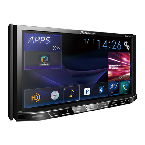
Other Pioneer Stereo Receiver manuals

Pioneer VSX-4500S User manual

Pioneer

Pioneer VSX-4500S User manual

Pioneer VSX-517-K User manual

Pioneer

Pioneer VSX-517-K User manual

Pioneer DMH-AF555BT User manual

Pioneer

Pioneer DMH-AF555BT User manual

Pioneer AVH-A205BT User manual

Pioneer

Pioneer AVH-A205BT User manual

Pioneer SPH-DA360DAB User manual

Pioneer

Pioneer SPH-DA360DAB User manual

Pioneer ELITE VSX-99 User manual

Pioneer

Pioneer ELITE VSX-99 User manual

Pioneer ELITE VSX-LX505 Manual

Pioneer

Pioneer ELITE VSX-LX505 Manual

Pioneer SX-2300 User manual

Pioneer

Pioneer SX-2300 User manual

Pioneer AVH-Z7050TV User manual

Pioneer

Pioneer AVH-Z7050TV User manual

Pioneer DMH-T450EX User manual

Pioneer

Pioneer DMH-T450EX User manual

Pioneer SX-20DAB-K User manual

Pioneer

Pioneer SX-20DAB-K User manual

Pioneer MVH-2400NEX User manual

Pioneer

Pioneer MVH-2400NEX User manual

Pioneer CT-S550S User manual

Pioneer

Pioneer CT-S550S User manual

Pioneer VSX-D704S User manual

Pioneer

Pioneer VSX-D704S User manual

Pioneer VSX-1022-K User manual

Pioneer

Pioneer VSX-1022-K User manual

Pioneer VSX-3000 User manual

Pioneer

Pioneer VSX-3000 User manual

Pioneer AVH-G225BT User manual

Pioneer

Pioneer AVH-G225BT User manual

Pioneer HTZ-222DVD User manual

Pioneer

Pioneer HTZ-222DVD User manual

Pioneer SX-600L User manual

Pioneer

Pioneer SX-600L User manual

Pioneer AVH-X8850BT User manual

Pioneer

Pioneer AVH-X8850BT User manual

Pioneer XC-L77 User manual

Pioneer

Pioneer XC-L77 User manual

Pioneer XC-L5 User manual

Pioneer

Pioneer XC-L5 User manual

Pioneer XR-P2000 User manual

Pioneer

Pioneer XR-P2000 User manual

Pioneer NO FOUND VSX-1020 Assembly instructions

Pioneer

Pioneer NO FOUND VSX-1020 Assembly instructions

Popular Stereo Receiver manuals by other brands

Denon AVR-2105 operating instructions

Denon

Denon AVR-2105 operating instructions

Aiwa AV-X300 operating instructions

Aiwa

Aiwa AV-X300 operating instructions

Planet Audio P650MB user manual

Planet Audio

Planet Audio P650MB user manual

Bang & Olufsen Beocenter 2500 Servise manual

Bang & Olufsen

Bang & Olufsen Beocenter 2500 Servise manual

Yamaha Aventage RX-A3040 Easy setup guide

Yamaha

Yamaha Aventage RX-A3040 Easy setup guide

Onkyo TX-RZ70 Initial setup guide

Onkyo

Onkyo TX-RZ70 Initial setup guide

Yamaha CR-820 owner's manual

Yamaha

Yamaha CR-820 owner's manual

Sony STR-K700 - Fm Stereo/fm-am Receiver Service manual

Sony

Sony STR-K700 - Fm Stereo/fm-am Receiver Service manual

Teac AC-V8500 owner's manual

Teac

Teac AC-V8500 owner's manual

Aiwa Z-VR55 Service manual

Aiwa

Aiwa Z-VR55 Service manual

Rotel RSX-1055 Bedienungsanleitung

Rotel

Rotel RSX-1055 Bedienungsanleitung

Nakamichi SR-2A Service manual

Nakamichi

Nakamichi SR-2A Service manual

Denon AVR-X3800H owner's manual

Denon

Denon AVR-X3800H owner's manual

Marantz ZR6001 user guide

Marantz

Marantz ZR6001 user guide

Sony STR-DA1000ES Service manual

Sony

Sony STR-DA1000ES Service manual

NAD T752 owner's manual

NAD

NAD T752 owner's manual

NAD T753 owner's manual

NAD

NAD T753 owner's manual

Yamaha R-700 owner's manual

Yamaha

Yamaha R-700 owner's manual

manuals.online logo
manuals.online logoBrands
  • About & Mission
  • Contact us
  • Privacy Policy
  • Terms and Conditions

Copyright 2025 Manuals.Online. All Rights Reserved.