manuals.online logo
Brands
  1. Home
  2. •
  3. Brands
  4. •
  5. Pioneer
  6. •
  7. Tape Deck
  8. •
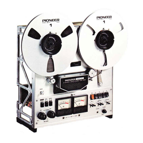
  9. Pioneer RT-1020L User manual

Pioneer RT-1020L User manual

This manual suits for next models

1

Other Pioneer Tape Deck manuals

Pioneer T-6600/F User manual

Pioneer

Pioneer T-6600/F User manual

Pioneer CT-9R User manual

Pioneer

Pioneer CT-9R User manual

Pioneer RT-707 User manual

Pioneer

Pioneer RT-707 User manual

Pioneer CT-1080R User manual

Pioneer

Pioneer CT-1080R User manual

Pioneer CT1270WR User manual

Pioneer

Pioneer CT1270WR User manual

Pioneer CT-F600 User manual

Pioneer

Pioneer CT-F600 User manual

Pioneer CT-W704RS User manual

Pioneer

Pioneer CT-W704RS User manual

Pioneer RT-1020LF User manual

Pioneer

Pioneer RT-1020LF User manual

Pioneer CT-9R User manual

Pioneer

Pioneer CT-9R User manual

Pioneer T-6600 Operating and safety instructions

Pioneer

Pioneer T-6600 Operating and safety instructions

Pioneer CT-F700 User manual

Pioneer

Pioneer CT-F700 User manual

Pioneer CT-200 User manual

Pioneer

Pioneer CT-200 User manual

Pioneer RT-1011L User manual

Pioneer

Pioneer RT-1011L User manual

Pioneer XC-IS21T User manual

Pioneer

Pioneer XC-IS21T User manual

Pioneer CT1270WR User manual

Pioneer

Pioneer CT1270WR User manual

Pioneer CT-1060W User manual

Pioneer

Pioneer CT-1060W User manual

Pioneer CT-1150R User manual

Pioneer

Pioneer CT-1150R User manual

Pioneer CT-W505R User manual

Pioneer

Pioneer CT-W505R User manual

Pioneer CT-A9 User manual

Pioneer

Pioneer CT-A9 User manual

Pioneer CT-980W User manual

Pioneer

Pioneer CT-980W User manual

Pioneer CT-50R User manual

Pioneer

Pioneer CT-50R User manual

Pioneer PRV-LX1 User manual

Pioneer

Pioneer PRV-LX1 User manual

Pioneer CT-3 User manual

Pioneer

Pioneer CT-3 User manual

Pioneer CT-730 User manual

Pioneer

Pioneer CT-730 User manual

Popular Tape Deck manuals by other brands

3M 3M-Matic Dual S-867 II Instructions and parts list

3M

3M 3M-Matic Dual S-867 II Instructions and parts list

SilverStone 1232 manual

SilverStone

SilverStone 1232 manual

Teac X-2000 owner's manual

Teac

Teac X-2000 owner's manual

Hitachi D-980MU Service manual

Hitachi

Hitachi D-980MU Service manual

Teac A-6010GSL Service manual

Teac

Teac A-6010GSL Service manual

Hitachi D-900BS Service manual

Hitachi

Hitachi D-900BS Service manual

Kyocera D-611 Service manual

Kyocera

Kyocera D-611 Service manual

Kenwood KX-W595 instruction manual

Kenwood

Kenwood KX-W595 instruction manual

TANDBERG 11 instruction manual

TANDBERG

TANDBERG 11 instruction manual

Teac Tascam 3030 owner's manual

Teac

Teac Tascam 3030 owner's manual

Sony DTC-670 operating instructions

Sony

Sony DTC-670 operating instructions

Teac A-3300 Service manual

Teac

Teac A-3300 Service manual

Kenwood KX-W6070 instruction manual

Kenwood

Kenwood KX-W6070 instruction manual

Sony DTC-A8 Service manual

Sony

Sony DTC-A8 Service manual

Tascam BR-20 Series maintenance

Tascam

Tascam BR-20 Series maintenance

Kenwood KX-620 instruction manual

Kenwood

Kenwood KX-620 instruction manual

uher SG 560 Royal Servise manual

uher

uher SG 560 Royal Servise manual

Kenwood KX-9050 instruction manual

Kenwood

Kenwood KX-9050 instruction manual

manuals.online logo
manuals.online logoBrands
  • About & Mission
  • Contact us
  • Privacy Policy
  • Terms and Conditions

Copyright 2025 Manuals.Online. All Rights Reserved.

Walnut venoered side panels are used in the con
struction of this cabinet.
flfl PIONEER
Thi> operating instruction booklet is available in
common for the operation of both models
RT-1020L and RT-1020H, the only difference of
which is “'l ape running speeds/’ Please note that
“RT-1020L” and “RT-1020H” in the explanations
are referred to as “RT-1020L/H.”
RT-1020L HI: 19cm/s (7-'/2 ips)
LO: 9.5cm/s(3-3
/4 ips)
RT-1020H HI: 38cm/s (15 ips)
LO: 19cm/s (7- 1
/* ips)
WHERE TO PLACE YOUR DECK
Model RT-1020L/H can be operated in upright as
well as horizontal position. When selecting the
place for your deck, avoid the following conditions
as they would affect the machine’s performance
and lead to trouble:
•Direct sunlight and the vicinity of heaters, etc.
•High humidity, poor ventilation
•Dust and dirt
IMPORTANT PRECAUTIONS
Always Keep the Tape Heads Clean
Dirt and tape abrasions on the tape head surfaces can
deteriorate the sound quality and lead to other trouble.
Make it ahabit to always clean the tape heads with the
supplied cleaning bar before each use (Fig. 1). For
stubborn deposits that the cleaning bar cannot remove,
refer to “Care &Maintenance'* on page 21.
Always Use Two Reels of the Same Size
The use of different size reels can obstruct proper tape
transport, causing damage to the tape. Always use two
reels of the same diameter and, preferably, shape. If one
reel is thinner than the other, place the supplied sheet
on the reel base for the thinner reel.
Always Apply the Reel Clamper if the Deck is in Upright
Position
Reel clampers to hold the reels in place are built into
the tips of the center shafts. Refer to Fig. 2. Place the
reel on the shaft, then pull up and twist the tip of the
shaft so that its protrusions will hold down the reel.
CAUTION!
Polish heads
carefully Fig. 1
RKKLS FALLING OFF WIIILK IN MOTION CAN BE
DANGEROUS. Pull tip of shaft /\
towards you,
then twist.
Fig. 2
The vicinity of electrical appliances that gener-
ate magnetism, such as TV sets, motors, trans-
formers, etc.
NOTE:
This model is to work on 120V AC. However,
it can also be adjusted for use on other voltages
at Pioneer authorized Service Center. For fur-
ther information, contact Pioneer Electronic Corp.
CONTENTS
WHERE TO PLACE YOUR DECK 2
IMPORTANT PRECAUTIONS 2
FEATURES 3
PARTS AND CONTROL FACILITIES 4
ASSEMBLY OE ACOMPONENT
STEREO SYSTEM 7
TAPE DECK CONNECTIONS 7
BASIC OPERATING INSTRUCTIONS 9
PLAYBACK 11
RECORDING 13
LIVE RECORDING WITH
MICROPHONES 16
4-TRACK MONOPHONIC RECORDING .... 16
MIXING 17
SOUND-ON-SOUND RECORDING 17
ECHO RECORDING 18
WHEN EMPLOYING DIGITAL TIMER 19
MAGNETIC TAPE 20
CARE &MAINTENANCE 21
KEYS TO SUCCESSFUL RECORDING
TECHNIQUE 22
TROUBLE SHOOTING CHART .../. 23
SPECIFICATIONS AND SCHEMATIC
DIAGRAMS Enclosed herewith
2
PIONEER
FEATURES
Sturdy Construction to Professional Standards
All mechanical parts are assembled on achassis made of
5mm thick aluminum of high dimensional precision and
supported by aunified diccast frame. This heavy-duty
construction gives high accuracy and long durability.
Precision Tape Transport Can Accommodate
10-inch Reels
The capstan is driven by a4/8-polc hysteresis synchronous
motor with alarge 100mm flywheel to maintain superb
speed accuracy without wow and flutter. The capstan
itself is machined to extremely precise tolerances.
The reels are driven by apair of specially designed 6-pole
inner rotor induction motors which combine the ideal
torque characteristics of eddy current motors with the
high starting torque of induction motors. No excessive
stress is applied to the tapes, thanks to the low rotational
inertia of the motors and the solenoid controlled dif-
ferential band brakes.
Three Tape Heads Including 4/2-channel
Playback Head
The combined 4/2-channel playback head features highly
precise track alignment, intimate lape-to-head contact due
to its hyperbolic curvature, and gives excellent performance
in regard to phase accuracy, linear frequency response
and crosstalk. In the recording head only 2-channel
stereo recording is possible much attention has been
paid to obtain optimum bias, signalto-noise ratio and
frequency response characteristics. Ihe three-head system
of course permits professional after-tape monitoring ol
arecording in progress.
Direct Coupled Playback Amplifier of Wide
Dynamic Range
For each of the four channels, a3-stage direct coupled
amplifier with low-noise silicon transistors is provided.
Its dynamic range goes it) beyond 20dB above OVU level.
2-track prerecorded master tapes can be played, too.
Separate Recording Amplifiers for Line and Mic
Inputs
The 2-channel recording amplifier features an excellent
signal to-noise ratio and awide dynamic range of 50dB.
Ihe microphone inputs are sensitive enough to permit the
use of studio-quality 600-ohm condenser microphones.
To maintain stable recording conditions regardless of
AC line voltage fluctuations or temperature changes, a
stabilized voltage supply has been adopted, while abias
current limiter has been included in the bias supply
oscillator circuit.
Independent level controls for the LINt and MIC inputs
permit effective mixing of program sources, "sing-along"
recording, sound-on-sound recording and other professional
processing methods.
Click Noises Prevented by Electronic Switching
Solid state electronic not mechanical switches in the
recording and playback equalizer circuits and adynamic
relay in the recording bias circuit prevent those unpleasant
click noises caused by normal switches.
3-position Bias Selector, 2-position Equalizer
Selector
To make the best of the extra quality potential of low
noise, high output tape (L.H. tape), proper bias current
and equalization are of paramount importance. On model
RM020L/H, biascurrcnt and equalization selector switches
have been provided to establish optimum recording
conditions for all types of recording tape now on the
market.
Swift-action Electronic Pushbutton Control with
Perfect Tape Protection
All transport functions are switched by electronic solenoid
pushbuttons. You can switch from any mode directly to
any other mode without having to push the stop button
and without fear of undue stress on the tape.
Automatic Recording in Your Absence
Ihe tape deck can be preset lor recording and, with the
help of an optional timer, can be energized at a preselected
time, for example to record an IMprogram that you
do not wish to miss.
Auxiliary Controls Worthy of aStudio Machine
Iape tension can be changed according to reel size.
Other controls include separate record switches for both
channels, a"recording" indicator equipped with alight
emitting diode, 4-channel/2-channel playback selector,
tape/source monitor switches lor front and rear channels,
aheadphone jack, etc.
Function Begets Form
Outward appearance matches technical excellence the
impressive looking control panel, large-sized LEVEL meters
and handsome controls are visual expressions of the high
level of technical performance that you can expect from
this tape machine.
3
PARTS AND CONTROL FACILITIES
PAUSE SWITCH
For short interruptions of tape travel. In position ON,
the tape is stopped while the unit remains in its previous
-recording or playback mode. At OFF, the tape
resumes travel at normal speed. Note, however, that the
PAUSE switch does not function during fast forward
or rewind.
LEVEL METERS
Indicate the recording and playback signal levels.
MIC INPUT JACKS
Iwo microphones lor stereo recording can be connected
here. Low-impedance (600oh ms) as well as high-impedance
(I Ok ohms to 50k ohms) can be used, but the cables
must have standard 60mm plugs.
POWER SWITCH
Push this button to turn the unit ON, push it again and
release it to turn the power OFF.
REEL SIZE SWITCH
Changes tape tension in accordance with reel size. For
7-inch (17cm) or smaller reels, push the button in.
When using 10-inch (26cm) reels, release the button.
IMPORTANT!
ALWAYS USE TWO REELS OF THE SAME SIZE.
TAPE SPEED SELECTOR
Pushbutton depressed: LO (low) tape speed.
Pushbutton released: HI (high) tape speed,
lo switch from LO to HI, push the button lightly
will return to released position.
RT-I020L HI: I9cm/s (7-1/2 ips) RT-I020H HI:
LO: 9,5cm/s (3-3/4 ips)
MIC RECORDING LEVEL CONTROL
Controls the recording level of live microphone recordings.
Clockwise rotation increases the recording level. This
control also governs the recording level when arecording
is made through the REC/PH connector (DIN- type) on
the rear panel.
LINE RECORDING LEVEL CONTROL
Controls the recording level that the signal is fed into
the INPUT (REC) jacks on the rear panel. Clockwise
rotation increases the recording level.
NOTE:
The MU' and LINE recording level controls both consist
of apair of friction coupled knobs; the inner knob
controls the left channel, the outer ring, the right
channel Usually, knob and ring rotate together, but
you can rotate one while holding the other in place
with your other hand
3Kcm/s (I5ips)
LO: l9cmM7-K.ps)
RECORDING INDICATORS
REC-L: Red light emitting diode lights up when the
lelt channel is in recording mode.
REC-R: Lights up when the right channel is in recording
mode.
For stereo recordings, confirm that both indicators are
lighted.
(TAPE COUNTER
Before starting a recording, reset the IAPt COUNfER to
"0000" by depressing the reset button. Use of the
IAPE COUNTER will make it easy to locate the starling
point of arecording.
“* TENSION ARM
Regulates tape tension, but also functions as an automatic
shut off sensor. If the tape is slack, breaks or runs out,
the automatic shut-off mechanism slops the tape transport
and returns all function buttons to neutral position.
—FUNCTION BUTTONS
STOP: Stops tape travel from any mode,
returns unit to neutral position.
PLAY: Makes tape travel at selected
speed. For playback, push this
button. For recording, push this
and the REC button.
REC: Activates recording circuits. To
start arecording, hold this
button down while pushing the
PLAY button.
*>> FAST FORWARD: Makes tape travel at high speed
from left to right.
<4 REWIND: Makes tape travel at high speed
from right to left.
NOTE
:
Unlike inconvenience of some kinds of tape machines on
the market, this model helps you switch from one mode of
operation to another without pushing the STOP button
That is. there is no need to push the STOP button when
switching from either FAST FORWARD or REWIND
mode to another, for instance, you can switch directly to
PLAY. Note, however, that such switching operation
always stops the tape travel once, momentarily, Afew
seconds more, and it will soon run at normal speed
•To go directly from FAST FORWARD or REWIND
to PLAY, refer to page I(I.
•For using thin tape in thickness, refer to NOTE on
page 12.
REC EQ SWITCH
Selects the recording equalization characteristics in ac-
cordance with the type of tape to be used.
STD: For recording on normal, conventional tape.
LH: For recording on low-noise high-output tape.
This switch has no function in playback.
REC BIAS SWITCH
Selects the proper bias current in accordance with the
type of tape to be used.
STD: For recording on normal tape. Smallest bias
current.
LH1, LH2: For recording on low-noise high output tape.
LH 2gives the strongest bias current.
Detailed instructions about the functions of the REC
BIAS and RLC LQ switches are given on page 14.
OUTPUT LEVEL CONTROL
Controls the output level that recorded tape is played
back. This is afriction-coupled type consisting of the
inner and outer knobs.
INNER KNOB: FRONT (CH.1, CH.3)
OUTER RING: REAR (CH.2, CH.4)
Usually, knob and ring rotate together, but you can
rotate one while holding the other in place with your
other hand.
PHONES JACK
Stereo headphones can be connected here for monitoring
or private listening. The METERS switch selects the
channels that you hear through the headphones.
PIONEER
-REC SWITCHES (L, R)
To make arecording, one or both of these switches
must be set at ON.
L: Recording on left channel
R:Recording on righ tchannel
For stereophonic recordings, set both switches at ON.
-PLAY SWITCH
Selects 4channel or 2-channel playback mode.
4CM: Playback of 4-channel recorded tapes
2CH: Playback ol 2-channel recorded tapes
-MONITOR SWITCHES (L, R)
Arecording in progress can be monitored (via speakers
or headphones) in either of two ways -the original
SOURCE sound, or the recorded TAPE sound as picked
up by the playback head. By switching back and forth
between positions SOURCE and TAPE/PLAY, you can
compare the original sound quality with that of the
recording and take corrective action if necessary.
Ihe left switch controls the left channel, the right
switch, the right channel.
-METERS SWITCH
Selects the channels to be displayed by the level meters
(and supplied to the headphone jack) when playing
4-channel recorded tapes.
FRONT: Front channels (CH. I*left, CH. 3cright)
supplied to level meters and headphones.
REAR: Rear channels (CH. 23left, CH.4 »right)
supplied to level meters and headphones.
AC POWER IN
Connect the AC power cord here.
—GROUND TERMINAL (GND)
Grounding is not necessarily required, but in the case
of hum or externally induced noise, the GND terminal
on the amplifier, or directly to earth.
—REC/PB CONNECTOR
Acombined input and output, for 2-channcl operation
only. If your stereo amplifier has an identical REC/PB
connector, you can establish all recording (INPUT), and
playback (OUTPUT) connections with asingle DIN cable
(optional) available from your Pioneer dealer.
Note that if connection is made to the REC/PB connector,
the recording level must be controlled with the MIC
level controls.
—INPUT (REC) TERMINALS
For recording, connect these inputs to the TAPE REC or
similar outputs of your stereo amplifier by means of the
supplied phono cables. Be sure to connect left channel
to LEFT, right to RIGHT.
—OUTPUT (MON) TERMINALS
For playback, connect these outputs to the TAPE
MONITOR, TAPE PLAYBACK or similar inputs on your
stereo or 4-channel amplifier.
With a4-channel amplifier:
FRONT LEFT to FRONT LEFT (CH. 1) of amplifier
FRONT RIGHT to FRONT RIGHT (CH. 3) of amplifier
REAR LEFT to REAR LEFT (CH. 2) of amplifier
REAR RIGHT to REAR RIGHT (CH. 4) of amplifier
With a2-channcl amplifier:
FRONT LEFT to LEFT CHANNEL of amplifier
FRONT RIGHT to RIGHT CHANNEL of amplifier
6
ASSEMBLY OF ACOMPONENT STEREO SYSTEM
Model RT-1020L/H is capable of 4-channel and 2-channel
playback as well as 2-channel recording but incapable of
4-channel recording. When combined with a4-channel
amplifier (such as Pioneer model QA-800A) and speakers,
it will give you superlative sound from 4-channel
prerecorded tapes. Instead oT a4-channel amplifier,
you can also use two 2-channel amplifiers. When con-
nected to only one stereo amplifier, model RT-1020L/H
functions as anormal stereo tape deck for recording and
playback, as shown in Figs. 3and 4.
4-CHANNEL
STEREO AMPLIFIER
(e.g. Pioneer QA-800A)
—I»ft oo••O O I
—It :oo••.ttt |
oo a
RT-1020L/H
FRONT
TAPE DECK CONNECTIONS
WITH A4-CHANNEL STEREO AMPLIFIER
Connections between tape deck and amplifier must be
made with the supplied phono cables as shown in Fig. 5.
Playback Connections
TAPE DECK AMPLIFIER
OUTPUT FRONT LEFT —TAPE INPUT
FRONT LEFT (CM. 1)
OUTPUT FRONT RIGHT TAPE INPUT
FRONT RIGHT (CH. 3)
OUTPUT REAR LEFT TAPE INPUT
REAR LEFT (CH. 2)
OUTPUT REAR RIGHT TAPE INPUT
REAR RIGHT (CI1. 4)
Recording Connections
Model KT-1020L/H cannot make 4-channel recordings.
For 2-channel stereo recording, connect the INPUT
(REC) terminals to the amplifier's TAPE REC or similar
tape outputs with tin* supplied phono cables, as shown
in Fig. 5. If the amplifier has front and rear channel
tape outputs, connect to the front channels unless you
specifically want to record the rear channel signals.
soTt:
Connections arc basically the same as in usmu hen -channel
amplifiers
wCH. 1CH. 3
LEFT ^RIGHT
.CH. 2CH. 4a
SPEAKER SYSTEMS Fig. 3
iTf
OO
2CHANNEL
STEREO AMPLIFIER
(e.g. Pioneer SA-9100)
I
OoOOo Oo|
w* 8v.vOvvOI
RT-1020L/H
SPEAKER
SYSTEMS LEFT RIGHT
INPUT OUTPUT
HfC.PB RPC MON
m0&
Fig. 4
LEFT
HIGH T
RT-1020L/H WHQNT
FURNISHED *
CORDS I•»
RECORDING PLAYBACK
OUTPUT INPUT
TAPE
REC MON L
<S—r-0 CM ’Q *
htj -H—
®
cm3 wi
R1I
II
•Il
FRONT
|LL0ch 2Qi>
l'r 0ih -*0 s:i>-
REAR
JACKS OF 4CHANNEL STEREO AMPLIFIER
Fig. 5
WITH A2-CHANNEL STEREO AMPLIFIER
Playback Connections
Connect the OUTPUT (MON) FRONT terminals of the
tape deck to the TAPE MON or similar tape inputs of the
amplifier, as shown in Fig. 6. Use the supplied phono
cables.
OUTPUT FRONT LEFT —TAPE INPUT
(MONITOR)
LEFT CHANNEL
OUTPUT FRONT RIGHT— TAPE INPUT
(MONITOR)
RIGHT CHANNEL
Recording Connections
Connect the INPUT (REC) terminals of the tape deck
to the TAPE REC or similar tape outputs of the
amplifier, as shown in Fig. 6.
INPUT (REC) LEFT —TAPE REC LEFT
CHANNEL
INPUT (REC) RIGHT TAPE REC RIGHT
CHANNEL
Connection Through DIN-type REC/PB Connector
If your stereo amplifier is equipped with aDIN-type
REC/PB connector (as most modern amplifiers and
receivers are), all playback and recording connections
can be made by linking this to the REC/PB connector of
the RT-1020L/H with asingle DIN cable (Fig. 7). Such
acable is available from your Pioneer dealer.
INPUT OUTPUT
REC MON
I I ®&
RT-1020L/H III!
FM>N
FURNISHED 111
CORDS hA1. A
JT-
RECORDING PLAYBACK
OUTPUT INPUT
\1
9
TAPE
REC MON L
00*>
<1 S>-
V
JACKS OF 2CHANNEL STEREO AMPLIFIER
Fig. 6
RT-1020L/H
REC PI
REC/P.B.
CABLE
(eg Pioneer
PP 101
)
ill
Connection to these
lacks not required
TAPE REC/P.B.
CONNECTOR (DIN)
ii «i
TAPE
REC PB
2CHANNEL STEREO AMPLIFIER Fig. 7
PIONEER
BASIC OPERATING INSTRUCTIONS
TAPE THREADING
As described in the foregoing, always use two reels of the
same size. You will find it practical to use chiefly 10-inch
or 7-inch reels rather than the very small ones.
1. Place the full reel on the left reel base, the empty reel
on the right base. When using the supplied or similar
10-inch reels, you also need the supplied reel adaptors.
See Fig. 8. These adaptors are not needed with 7-inch
or smellier reels.
Differences in reel thickness can be compensated by
placing the supplied sheet under the thinner reel as
shown in Fig. 9.
2. Secure the reels in place by pulling up the tips of
the center shafts and twisting them about 3to 4mm
to the left or right so that their protrusions will hold
the reels down. Make it ahabit to always secure the
reels in this way —unsecured reels could fall off and
cause damage (Fig. 10).
3. When using 7-inch or smaller reels, push down the
REEL SIZE switch. With 10-inch reels, no need to
push it down (Fig. 11).
4. Before threading the tape, lock the guide roller arm,
as shown in Fig. 12. This locking mechanism is
provided for convenience in threading the tape. Then
thread the tape as shown in Fig. 13. Be sure to insert
the leading end of the tape correctly into the take-up
reel slot, since if it is not properly secured, slippage
may occur when the tape is running. Turn the reel 3
or Irevolutions to take up any tape slack.
Do not forget to release the guide roller arm lock
lx* fore running the tape.
REEL ADAPTOR
Fig. 10 Fig. 11
TAKE UP
REEL
PINCH
ROLLER
GU IDE —
ROLLER
4TENSION
ARM
GUIDE ROLLER
•Above numbers indicate tape threading Sequence
9
TAPE TRAVEL (Fig. 14)
1. First, confirm that all function buttons are in neutral
position. Otherwise, push the STOP button once.
2. Push the POWER switch. The LEVEL meters will
light up and the capstan will begin to rotate.
3. Push the PLAY button. The tape now travels from
left to right.
4. Push the STOP button. The tape stops.
TAPE SPEED SELECTION (Fig. 15)
As long as the SPEED selector is released, the speed
remains set at III. For 1.0 speed, push the selector. To
release it again, push it once more.
RT-1020L HI: 19cm/s (7-V& ips)
LO: 9.5cm/s (3-% ips)
RT-1020H III: 38cm /s (15 ips)
LO: 19cm/s(7-'/jips)
THE PAUSE SWITCH (Fig. 16)
The tape traveling at normal speed can be stopped by
setting the PAUSE switch at ON. Return it to OFF,
and the tape will resume travel. Note, however, that the
PAUSE switch does not function during fast forward
or fast rewind.
FAST FORWARD, REWIND (Fig. 17)
1. For fast winding from the left to the right, push the
FAST FORWARD button. For fast rewinding, push
the i* REWIND button.
2. To stop the tape, push the STOP button.
3. If the tape runs out or breaks, it will stop automatic-
ally.
Bv employing the PAUSE switch, tape motion can be
immediately changed from FAST FORWARD or REWIND
to PLAY (see Fig. 18).
When the PLAY button is depressed while the tape is in
FAST FORWARD or REWIND, afew seconds will elapse
before normal speed is attained. This is to protect the
tape. In situations such as looking for the start of a
recorded passage, cueing, etc., where it is desired to set
the machine immediately to PLAY, perform the following
steps.
1. Set the tape motion to 8> FAST FORWARD or
<3 REWIND.
2. Depress the PLAY button.
3. After the tape has come to a complete stop, operate
the PAUSE switch ON-OFF. By doing this, the tape
will begin to move at normal speed.
It is important to wait until the tape has stopped
completely before operating the PAUSE switch to
avoid possible damage to the tape or mechanism.
3Fig. 14
sniro
i©
Push Fig. 15
>wuW
Fig. 17
/
/
Fig. 18
Above numbers indicate operating sequence.