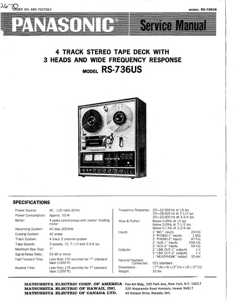
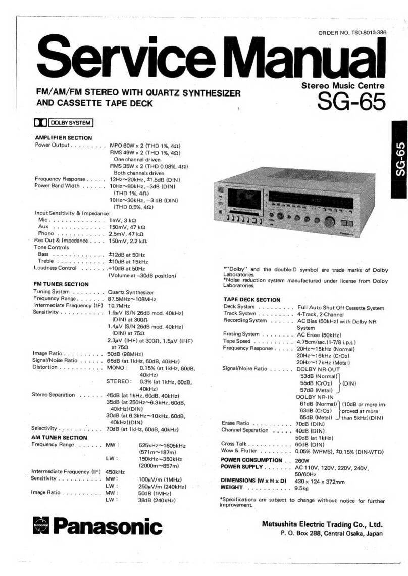
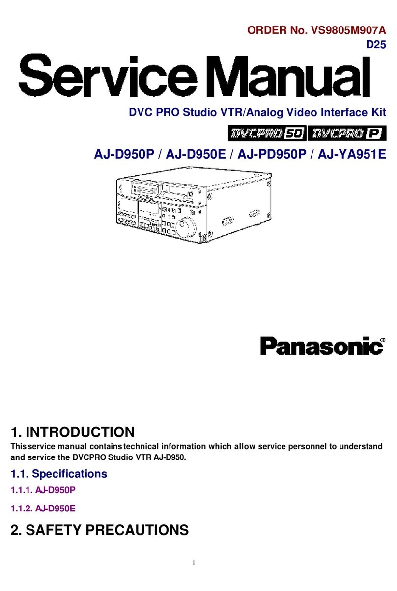
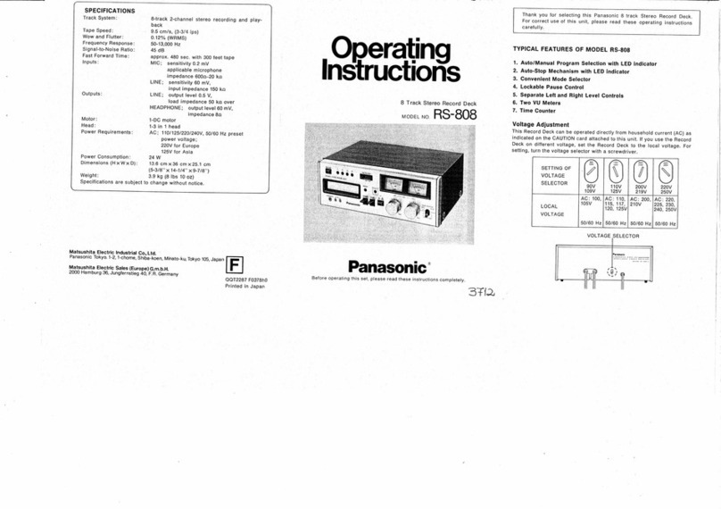
Panasonic RS-856 User manual

ORDER
NO.
ARD81070076C4-07
8-Track
Tape
Deck
—
RS-856
Stereo
8-Track
Record/Playback
Deck
—
with
LED
Level
Meters
RQ-831
MECHANISM
SERIES
Specifications
Track
system:
8-track
2-channel
stereo
recording
and
playback
Recording
system:
AC
bias
(40
kHz)
Tape
speed:
9.5cm/s
(3-3/4
ips.)
Wow
and
flutter:
0.15%
(WRMS)
Tape:
&-track
cartridge
tape
Frequency
response:
50
—
12,000
Hz
Signal-to-noise
ratio:
45
dB
Inputs:
2-Mic:
=72
dB
(0.2
mV)/200
—
1,000
2-Line:
—24
dB
(60
mV)
Out
puts:
2-Line;
600
mV/50
kQ
|
1-Headphone;
60
mV/8
Q
Head:
3-in-1,
8-track
2-channel
stereo
head
Fast
forward
speed:
Approx.
19cm/s
(7-1/2'/s)
Power
requirement:
AC;
90—109/110—125/200—
219/220—250V,
50-60
Hz
Pre-set
power
voltage
110—125V,
220—250V
for
Europe
Power
consumption:
9W
Dimensions:
~315.0mm(W)
X
200.0mm(H)
X
92.5mm(D)
[12-1/2"(W)
x
7-7/8"(H)
X
3-5/8"(D)}
=
Weight
:
6
2.88
(6
lbs,
-Z.0z)
|
Specifications
are
subject
to
change
without
notice.
Panasonic
Tokyo
Matsushita
Electric
Industrial
Co.,
Ltd.
_
1-2,
1-chome,
Shibakoen,
Minato-ku,
Tokyo
105
Japan

ITEM,
PAGE
ae
i
LOCATION.
0
OF
CONTROLS
AND:
COMPONEN
1
oiithi
eset
recat
l
~
DISASSEMBLY
INSTRUCTIONS.
+++--0-se-sessessseseeeseteseeeeetentente
nee
ntenticen
eer
eet
2
DISASSEMBLY
NOTE.
--s--ss-ssessssssesstessessessessesseeseressetenstesteseenterecensensceesensasscessessessne
at
3
:
ASSEMBLY.
NOTES
crsesesesesseeeeeteteeeneteneneneee
ss
vipiwaniandnobienseusetes
eee
ee
psiiseeeenegnins
3
MEASUREMENT
AND
ADJUSTMENT
-ccececcccctecceeet
tens
ene
enneene
ene
eneeneenes
ees
cnseeee
ent
ene
eens
enn
e
eee
4
Bacia\
uglegal
\el-2:|
|
ere
eee
ee
erent
eter
are
ere
5
CIRCUIT
BOARDS
AND
WIRING
CONNECTION
DIAGRAM
ites
resscuitis
Sante
dee
ee
ated
pea
6
ELECTRICAL.
PARTS:
LOCATION
siecuesacwsiaeanenatevecrcaner
eames
ee
ne
ene
Un
eee
ere:
6
MECHANICAL
PARTS
LOCATION
-++--ésccsssscescessseseseeceteeceeeesresseneetertaseseessesseseessesseena
ea
7
CABINET
PARTS
LOCATION
«+-+--+-sssssesseseseseesesssseesseeecaeenetensensencenesensentenensceecrscsecens
es
7
“LOCATION
OF
CONTROLS
AND
COMPONENTS
Time
Counter
&
Reset
Button
Record
Indicator
(RECORD)
[TIME
COUNTER
(MIN
-
SEC)}
see
ainnahars
ie
id
aa
(LEFT
LEVEL
-
RIGHT
LEVEL)
(PROGRAM)
-~———>——)———
|
.
|
Peemsonte
oe
ae
oe
ie
a
“O-O-|
Pause
Button
a
Microphone
[PAUSE
(MOFF
-
=
ON)]
MIC
(LEFT
:
Record
Button
(|RECORD))
RIGHT)]
Fast
Forward
Button
[FF
(@OFF
-
=ON)
Level
Adjustment
Controls
[LEVEL
(LEFT
-
RIGHT)]
Voltage
Selector
(VOLTAGE
_
SELECTOR)
ihe
Sa
peg
ERE
RIE
GH
ES
Sceeh
DURY
M
BcaE
BN
RS
TRIS
ee
ESE
eatin
Sg
ae
aed)
wi
i
Sect
os
We
Pi ee
in
te
Sa
a
ate
ee
ei
es
bk
Beene
ape
sd
ies
eta
Seg
Ok
ase
Poa
as
ek
are,
EE
ee,
bas
besad
shhn
ee
Gt
sere
Bee
ited
teen
Poet
i
Beko
ZBI
op
RE
ahs
e
Connection
Cord
ss
Power
Cord
(LINE
OUT)
(AC
IN
120V)
Connection
Cord
(LINE
IN)
Procedure
To
remove
——;
ie
Remove
——..
Notice:
See
the
disassembly
note
at
page
3.
Shown
in
fig.
———.
Case
cover
e
4
black
screws
©
?
SCYEWS
«ee
+
Back
board
°
?
screwS
«+:
i
|
Program
circuit
board
*
3
red
screws
Level
indicator
circuit
board
aa
e
?
red
screws
Front
panel
assembly
[3-54-5556
————+
Mechanism
unit
e
|
red
screw
-
*
6
screws
--:
¢
Counter
belt
----
«
2
volume
knobs
*
3
pin
socket
----
|
°
2
red
SCTOWS
seer
teres
ens
asec
e
eens
et
one
«
2
cord
clampers
and
2
red
screws:
137334
55-—/7
Main
circuit
board
+
e
3
red
SCTOWS
o
80
ee
see
sen
scenes
nese
eeenes

DISASSEMBLY
NOTE
MECHANISM
SECTION:
Wie
ee
eee
Remove
the
brake
shaft
(M54)
from
the
brake
guide
(M4)
and
push
the
detection
rod
assembly
(M35)
up
in
the
direction
of
arrow
A.
Remove
the
mechanism
unit
while
lifting
it
aslant
as
shown
by
arrow
B.
(shown
in
fig.
A)
Detection
rod
assembly
(M35)
Record
Brake
guide
(M4)
Brake
shaft
(M54)
Fig.
A
ASSEMBLY
NOTES
MAIN
CIRCUIT
BOARD
SECTION:
When
mounting
the
main
circuit
board,
be
sure
to
check
that
the
record/playback
select
switch
(S1)
and
record
lever
assembly
(record
lever
(M40)
and
record
lever
spring
(M41))
are
properly
positioned.
(shown
in
fig.
A)
MECHANISM
SECTION:
Set
point
A
of
the
mechanism
guide
angle
to
angle
A
of
the
mechanism
unit.
(shown
in
fig.
B)
Litt
the
left
side
of
the
mechanism.
Insert
the
brake
shaft
into
the
specified
position
of
the
brake
guide,
as
shown
in
fig.
A.
Push
the
detection
rod
assembly
(M35)
up
in
the
direction
of
arrow
A.
(shown
in
fig.
A)
Slide
the
mechanism
unit
in
the
direction
of
arrow
C.
(shown
in
fig.
B)
At
this
time,
make
sure
that
point
B
of
the
detection
rod
assembly
is
inserted
into
the
opening
between
the
mechanism
unit
and
metal
boss
assembly
(M2).
QAWVO
Detection
rod!
assembly
|
Point
B
|
(M35)
Mechanism
|
unit
Angle
A
Point
A
(G20)!
a
Mechanism
oe
guide
angle
|

MEASUREMENTS
AND
ADJUSTMENTS
[eae
[ee
NOTES:
Keep
good
condition,
set
switches
and
controls
in
the
following
positions,
unless
otherwise
Specified.
@
Make
sure
head
is
clean.
©
e
Fast
forward
switch:
OFF
@
Make
sure
capstan
Is
clean.
@
Record
switch:
OFF
,
@
Judgeable
room
temperature:
20+5°C
(68
+9°F)
@
Volume
controls:
Maximum
|
_
Connect
the
LINE
OUT
cords
to
the
VTVM.
@
Pause
switch:
OFF
:
Head
height
.
Place
the
set
into
the
mode
of
program
es
| |
adjustment
_
Play
the
test
tape
QZZVTT801
and
adjust
head
:
height
adjustment
screw
for
minimum
output.
Test
tape
Sree
PROCEDURE
METHOD
MEASURING
FIGURE
Q2zVTT801
Fig.
6
|
are
*
Head
height
adjust
screw
is
shown
in
fig.
1
of
.
Oy
__
Lock
roller
Step
1.
|
sit
soe
\
9)
Ton
ae
i
|
Insert
the
standard
cartridge
In
the
cartridge
slot
and
.
ehh.
—>
spring
gauge
|
|
Connect
the
LINE
OUT
cords
to
the
VTVM.
}
3
|
Pressure
of
take
the
measurement
by
pulling
it
with
the
spring
3
ee
Place
the
set
into
the
mode
of
program
iL
LINE
OUT
1
pressure
roller
Sauge.
.
.
Play
the
test
tape
QZZVTT804
and
measure
the
Standard
value:
5}00—850g
Head
azimuth
output
(original
signal).
“
ee
oh
|
pean
.
Changeover
to
program
2,
play
and
measure
the
\2—
)
7
Crosstalk
output
(crosstalk
signal).
adjustment
.
Read
the
ratio
between
original
signal
and
crosstalk
feat
tues
|
,
signal
in
dB.
QZZ2VTT804
Tension
gauge
.
Adjustment
should
be
repeated
steps
4,
5
and
6
|
ry
f
above.
|
|
Standard
value:
more
than
50dB
p
h
Apply
the
tension
gauge,
push
in
the
arrow
direction
and
rogram
change
De
eae
measure
the
maximum
value
at
the
end
point.
“a6
aieeRAROIINE
OUT
eae
ta
aRN
Standard
value:
less
than
2g
Program
select
lever
|
2.
Play
the
test
tape
QZZ8FC
and
measure
the
output
|
level
on
the
VTVM.
|
;
Playback
gain
Plunger
adjustment
Standard
value:
0.6+0.1V
|
Fig.
2
.
If
measured
value
is
not
within
standard,
adjust
VR3
|
(L-CH),
VR4
(R-CH).
|
|
Tension
gauge
Test
tape
gaug
(Shown
in
electrical
parts
location
at
page
6.)
QZZVTT801
;
:
Place
the
set
into
the
mode
of
program
1,
and
take
the
x
-
.
Test
equipment
connection
is
shown
in
fig.
9.
|
measurement
by
pushing
the
head
downward
with
the
r
.
Place
the
set
into
record
mode.
3
Head-up
tension
|
tension
gauge.
|
.
Read
voltage
on
VTVM
and
calculate
erase
current
Standard
value:
19g
or
more
Sy
by
following
formula.
Erase
current
c
t
(A)
=
Value
read
on
VTVM
(V)
Head
azimuth
adjust
screw
adjustment
FaSe
Curren
=
10Q
|
Standard
value:
8+1mA
:
_
4.
If
measured
value
is
not
within
standard,
adjust
VR7.
one
OUT
(Shown
in
electrical
parts
location
at
page
6,)
.
Connect
the
LINE
OUT
cords
to
the
VT
VM.
|
-
.
Place
the
set
into
the
mode
of
program
1.
:
.
Play
either
a
test
tape
QZZVTT801
or
recorded
|
(0)
Heed
rari
music
tape.
|
|
:
4
ont
.
foererre)
Turn
head
height
adjustment
screw
counterclockwise
_
Test
equipment
connection
is
shown
in
fig.
10,
AF
oscillator
a
mrcrer
Aes
ED
to
raise
head
to
highest
position.
;
7
,
aoa
ig
7
Test
tape...
Recorded
.
Place
the
set
into
record
mode.
Fig.
10
.
Next,
turn
head
height
adjustment
screw
Clockwise,
QZZ7VTT801
°
music
tape
.
Supply
1kHz
signal
(—24
dB)
to
the
LINE
IN
cords.
gradually
lowering
head,
and
stopping
where
first
Fig.
4
_
Adjust
at
“O
dB".
|
yh
AAAAAA
sound
heard
is
at
maximum
level.
|
wea
|
|
A.
Adjust
the
ATT
so
that
the
output
level
at
LINE
ce
qo).
ooo
%*
Adjustment
point
(head
height
adjust
screw)
is
OUT
cords
becomes
0.5
V.
=
shown
in
fig.
1
of
step
1.
eageaaas
B.
Adjust
VR5
(L-CH),
VR6
(R-CH)
so
that
the
RH
COC
ICICICI
10
adjustment
QdB
LED
lights
up
(see
fig.
11).
| 3
“vy
VVVVVVY.
©
(Shown
in
electrical
parts
location
at
page
6)
5
3
fb}
&
Bite
.
Adjust
at
“+3dB”.
Fig.
11
A.
Adjust
the
ATT
so
that
the
output
level
at
LINE
|
|
.
Connect
the
LINE
OUT
cords
to
the
VT
VM.
:
oi
ie
(eee
oe
:
wh
Ad
AAAAAAA
;
.
Place
the
set
into
the
mode
of
program
2.
.
Adjust
Ch),
-GH)
so
that
the
cas
COCCI
5
Head
acu
.
Play
either
a
test
tape
QZZVTT8O1
or
recorded
7
+3dB
LED
lights
up
(see
fig.
12).
=
|
adjustment
maisie
tape.
frees.
.daeetics
.
Repeat
twice
between
4
and
5
above.
Hq
COCOICICICY
.
Adjust
head
azimuth
screw
for
maximum
level.
QZZVTT801
™
music
tape
%
i
a
A“vvy
VYVVVVYY
Fig.
5
Jer
5.
©
fo)
+dB
3
Head
azimuth
screw
is
shown
in
fig.
3
of
step
3.
Fig.
12

soe
ry
7g
hi
Sh
a
ce
aE
|
RS-856
Hi
|
;
4
4)
6
|
7
8
1
2 3
|
|
NOTES:
RESISTORS
CAPACITORS
: |
,
|
ERD...Carbon
ECBA
......
Ceramic
*ECOF
f:.2.,
Polypropylene
RAM
ERG...Metal-oxide
ECGD......
Ceramic
ECE
g.00
Electrolytic
SC
i
EMATIC
DIAG
ERS
...Metal-oxide
ECKD......
Ceramic
ECEON
...Non
polar
electrolytic
ERO...Metal-film
ECCD......
Ceramic
ECQS
......
Polystyrene
er
ee
ee
ee
ee
ee
ee
ee
ERX
...Metal-film
ECFD
......Ceramic
ECSO......Tantalum
|
er
51-2
IC1
$1-3
2SD636R
2SD636R
Q7
OAS0MFV
|
a
es
gente
cnt
fy
et
ERQ...Fuse
type
metallic
ECQOM......
Polyester
film
QCS_.......
Tantalum
UPC1186H2
[2SD636S]
[2SD636S]
2SD638R
[20A90]
|
“]
ERC...Solid
ECOQE
......
Polyester
film
A
|
PLAYBACK
EQ
a)
MUTING
LINE
AMP
LINE
AMP
j
'C2,3
BA6S6
|
ERF
...Cement
|
1
Pog
at
RIL
82K
QQ
|
|
REVEL
INDICATOR
!
B+
(bias
uN
me
ta
RS,
120K
ener
=m
—
|
|
|
REPLACEMENT
PARTS
LIST
89K
R4l
4.7K
|
|
|
Important
safety
notice
Q5
A 0
|
Components
identified
by
A
mark
have
special
characteristics
important
for
Safety.
F
a4
820K
|
l
When
replacing
any
of
these
components,
use
only
manufacturer's
specified
parts.
D
|
Part
No.
Part
No.
Ref.
No.
Part
No.
@
|
C44
ECEA1CS471
RESISTORS
CAPACITORS
C46
ECFWD103MxY
.
ue
|
|
|
R1,2
ERD25FJ561
C1,2
ECKD1H102KB
|
!
R3,
4
ERD25TJ124
C3,
4
ECEA2AS010
TRANSISTORS
ly
|
R5,
6
ERD25FJ222
|
C5,
6
ECEAICS330
—-1Q1,2,3,4,5'6
C23
0.0033
R7,8
ERD25FJ101
C7,8
ECKD1H222KB
2SD636S
‘
PLAYBACK
<>
State
>
|
R11,
12
ERD25TJ823
C11,
12
ECFWD153MXY
|Q11,
12
2SD636S
B
HEAD
a
Y
|
l
R13,14
|
ERD25FJ560
«113,14
|
ECKD1H331KB
1013.14
|
2SD592NCR
(WYB12A)
|
s-4
$1-5
$1-6
-
Ad
ae
ge
A
|
R15,16
|
ERD25FJ822-|C15,16
|
ECEAIHSR11
|
8
R17,
18
ERD25TJ333
C17,
18
ECEA2AS010
DIODES
&
|
boo
oo
ai
ear
SSDS
|
msz0/emoseca
|ois20
scenes
necriiens
Ra
ibor
|
C21,22
|
ECEASOZR33.
«p12
20A90
LINE
ae
aa
3
|
R21,22
|
ERD257J824
D3,4
MA161
Weick
“egy
aor
|
R23,24
/
ERD25FJ271
©
|C23,24
~—-|
ECFWD332MXY
|D5,
6
SM112
an
|
R25,
26
ERD25FJ562
C25
ECEA1CS101
D7,8,9,
10,
11,
12
|
.2V)
C10
|
R27,28
|
ERD25TJ274
|
C26
ECFDD104MXY
A
|
SM112
i
R29,
30
ERD25TJ823
C31
ECQM1H152KZ
D13,
14,15,
16,17
©
|
R31,
32
ERD25FJ151
C32
ECQM1H223KZ
LN21RP
a
ons
Rip
8.2K
os
|
R33,
34
|
ERD25FJ101
{33,34
|
ECKD1H222KB
{p18,19
|
LNOS201PKL
|
R10
1K
|
R35,36
—_
|
ERD25FJ390
=
son
;
a
D20
MA1110
123
|
10K
R37,
38
ERD25FJ222
|
Pek
!
R39,40
|
ERD25FJ392
|
C37
ECEAIES470
THYRISTOR
|
C38
ECEA1CS221
SCR1
M21C
3
|
R41,42
|
ERD25FJ472
:
SS
De
TO
0
ne
rs
R43,
44
ERD25FJ103
C39
ECFWD103MXY
Geeuahakes
tee
EAYBA
CK
<>
‘an
R45,46
|
ERD25FI271
‘|
C40
ECEAICS221
HEAD
wy.
Se
rege
R47,48
|
ERD25TJ183
|
C41,42
|
ECEAICSA71
~—‘Jicy
UPC1186H2
Q9,
a
2SD636R
Qi2
Sot
Se
Sty
eee,
2,
=
ERD25FJ152
[C43
A
ECEAICS471
~—‘f
12,3
QViBA656
2sD638F
si.
[2SD636S)
si-7
2SD636R
Q13
1
ERD25FJ472
[2SD636S]}_
§
2SD592NCR
Q14
D7—12
|
R51,52
|
ERD25FJ471
€33.
0.0022
z
03
MOTOR
DRIVER
MOTOR
DRIVER
D5,
6
2SD592NCR
1SR35200FV
R53,54
|
ERD25FJ221
7
OD
R74
1SR35200
REGULATOR
[SM112]
|
ERD25FJ100
Part
No.
Part
Name
&
Description
Pagy.
S611
[SM112]
B+
(bias)
|
R62,63
|
ERD25FJ3R9
}
[i
ee
SB
R76
|
ann
ERD25FJ822
T1
QLBO170S
Bias
Oscillation
Transformer
Rey
|
KILLER
ERD25FJ103
T2
A
|
QLPN43HJX
Power
Transformer
ERASE
l
ERD25FJ102
en
ERD25FJ103
SWITCHES
R69
ERD25FJ102
Sl
QSSA206
Slide
Switch
=,
ERD25FJ272
(Record/Playback
Selector)
<
Rp
C4
ERD25FJ103
$2
QSW4211
Slide
Switch
D
=
AC
IN
ERD25FJ392
(Fast
Forward
ON/OFF)
ERD25FJ821
$3
Refer
to
M68
and
M71
ERD50FJ560
Rotary
Switch
(Program
Indicator)
R70
FUSE
0.5A
$4
QSB0226MS
Leaf
Switch
(Program
Selector)
2.7K
L
ERG2ANJ330
$5
Refer
to
M29
Sensing
Switch
ERD50FJ220
56
QSB0232M
Leaf
Switch
(Cartridge
Detection)
D20
D3,
4
Se
Oe
A
|
ERD25FJ272
$7
A
|
QSM0062
Micro
Switch
(Power
ON/OFF)
IMA1110]
R78,79
Aj}
ERD25FJ152
$8
A
|
QSR1403H
AC
Power
Voltage
Select
Switch
boo
att)
mato
O-0
-O
—
—
4
ERD25FJ101
ince
55
ERD25FJ1RO
—
J1,2
QEJ2001
Microphone
Jack
VARIABLE
J3
QJA0249H
Headphones
Jack
RESISTORS
eee
VR1,2
|
EVHGHAF25A54
BOSE.
B
bial.
VR3,4
|
EVNK4AA00B54
A|XBALEOSNR3
|
Fuse
;
9
DI4-17
Q
y)
VR5,
6
EVNK4AA00B14
|
LNI2IR
VR7
|
EVNK4AA00B54
Ln
a
a
a
et
SPECIFICATIONS
*
Volume
controls
maximum.
;
NOTES:
EQ
UIVALENT
CIRCUIT
e
$1-1—S1-10......
Record/Playback
Select
switch
(shown
in
playback
position).
*
Resistance
are
in
ohms
(Q),
1/4
watt
unless
specified
otherwise.
IC2.
3
BAGS6
¢
$2-1—S2-3
......
Fast
Forward
ON/OFF
switch
(shown
in
OFF
position).
K
=
1,0002,
M
=
1,000KQ.
4
dats
Dn
REE
SPC
NO
Program
indication
select
(switch
shown
in
program
1
position).
¢
Capacity
are
in
microfrads
(uF)
unless
specified
otherwise.
vec
VREF
6
4
eos
wines
Program
selector
(shown
in
OFF
position).
P
=
Pico-farads.
1
kHz:
100#z:
7.5kHz:
+1+5dB
OdB
Th
dB
Playback
frequency
response
«
Use
test
tape
QZZ8FC
‘cas
(9)
=
&
ep
ne
>
Bie
2
=
(3)
~~
(4)
~—
iad
are
|<
eee
ne
Sensing
switch
(shown
in
OFF
position).
*
The
mark
(¥)
shows
test
point.
e.g.
V
=
Test
point
1.
|
OSG
os
otvesisheseatens
Cartridge
detection
switch
(shown
in
OFF
position).
*
All
voltage
values
shown
in
circuitry
are
under
no
signal
condition
and
record
Playback
S/N
ratio
40
dB
or
more
|
i>
7
are
er
eh
Power
ON/OFF
switch.
~
mode
with
volume
control
at
minimum
position.
;
|
|
OSB
i
isiitelensienengies
AC
Power
voltage
select
switch.
For
measurement,
use
VTVM.
Bias
oscillation
frequency
|
|
OVA.
seceseceetes
Volume
control.
*(
(©)
)
this
arrow
indicates
the
flow
of
the
playback
Signal.
F
VR
©
VR3,4
oo...
Playback
gain
adjustment
VR.
e
(
»
)
this
arrow
indicates
the
flow
of
the
recording
signal.
os
1a
0.3mA
=
Reg
ae
B
t
©
VR5,6
oo...
Level
indicator
adjustment
VR.
laS
Curren
[Measure
at
TP2(L-CH),
TP3
(R
CH)]
|
Le
VRT
ec
Erase
current
adjustment
VR.
¢
This
schematic
diagram
may
be
modified
at
any
time
with
:
|
the
development
of
new
technology.
Sea
ianod
MIC:
_72+4d8
a:
.*
andard
recording
level
-
|
:
7 |
LINE
IN:
—24+4dB
lo
ae
=a)
|
|
|
(00)
ar]
ad
=

CIRCUIT
AIR
Nese
nncetii
het
ENP
NPE
ONE
SERRE
REESE
AONE
ELLE
AEP
GEEOCES
EIS
BSAA
SIAL
SUNEAARE
Dt
abentpestespieséoenspaseeasnipiictedensravsmnesnraneapied
sototeneeene
BRN
a
oe
&
#
oa
sok
AR
BLK}
VLT|GRN
:
S5:
SENSING
SIDE
VIEW
SWITCH
IC1
UPC1186H2
|
SWITCH
(S3)
LB
|
CIRCUIT
|
:
.
J
war
IC2,
3
BAGS56
|
P
RZ.
|
aN
SOLENOID
COIL
$
|
/\
SLD
RED/A
Le
|
~
|
Nee
ee
ee
ee
‘
|
WHT
S)
S
rN}
|vut
MIC
IN
JACK
:
ies
i
ae
T2:
POWER
|
,
ie
ee
ac
TRANSFORMER
|
CARTRIDGE
DETECTION
®]
|
:
SWITCH
-=
:
|
S8:
AC
POWER
:
VOLTAGE
|
SELECT
|
SWITCH
SA
8a
BT
@QOOOOaS
t(D
Pa
Cc
m
rm
=
el
i.8v|
2SD636R
rc
"
a
rey
es
ra
7
1E}
0.0-V-]
2SD636S)
Bee
ats
E23:
SPARK
-
Ch
8V
leanrasnan
‘
epg
yi
Se
SS2NCR
KILLER
FEL
iS
F1:
FUSEO.5A
$7:
POWER
ON/OFF
SWITCH
2
NOTES:
E
:
BLK
--+.-:
Black
BLU
...-..
Blue
BRN
-..---
Brown
GRY
«+:
Gray
GRN.--:.-
Green
L.
BLU---
Light
Biue
|
NIL
eee.
No
Color
Mark
:
|
ORG:
sss
Orange
Seeoteeliene!
2
BR
BEE
RED
:.--..
Red
_|
AG
FOWER
SLD’:
.++.:
Shield
Wire
Bray
CORD
Wie,
Violet
(el
ove
WHT.-:---:
White
(eC
ov
|
YEL
«+--+:
Yellow
F
NOTES:
#
The
circuit
shown
in
£4
n
the
conductor
is
B+
(bias)
circuit.
e
The
circuit
shown
in
;
on
the
conductor
indicates
printed
circuit
on
the
back
side
of
the
printed
circuit
board.
[erence
e
Values
indicated
in|
:
are
DC
voltage
between
the
ground
and
electrical
parts.
e
The
voltage
indicates
are
measured
during
record
mode.

eee
LEVEL
INDICATOR
CIRCUIT
BOARD
OO
©OODOO}
R73
A
7
4
igi
,
z
R53
&
OSS
SIR
BRS
AN
Na
resent
Boe
ee
ODOOOOHA
ay
cesneonconnecense
BLK]
VLTIGRNI
SIDE
VIEW
IC1
UPC1186H2
WHT
wet
IC2,3
BA6SG6
oe
|
aeons
T2:
POWER
one
rere
cette
ene
ae
TRANSFORMER
~
CARTRIDGE
DETECTION
:
SWITCH
PISS
a
S8:
AC
POWER
:
=
ORG
VOLTAGE
¢
SELECT
BLU
BLU
SWITCH
|
1D
eS
fatacoct
ee
E23:
SPARK
oA
;
fe
POSS
Le’
28D592NC
KILLER
Ae
&
cyg
CIRCUIT
BOARD
Recess
F1:
FUSE0.5A
Z
;
een
E16
S7:
POWER
|
5
REPLACEMENT
PARTS
LIST
ON/OFF
SWITCH
NOTES:
important
safety
notice
-
1
BEKess:.
Black
Components
identified
by
A
mark
have
Special
characteristics
important
for
safety.
BLU
..-...
Blue
When
replacing
any
of
these
components,
use
only
manufacturer’s
Specified
parts.
BRN
..--.-
Brown
—
:,
GRY
------
Gray
Part
No.
Part
Name
&
Description
Ref.
No.
|
Part
No.
Part
Name
&
Description
GRN..--.-
Green
|
EYES
|
Pe
:
:
L.
BLU--.
Light
Blue
ELECTRICAL
PARTS
7
E15
XTN3+6B
Tapping
Screw
®3x6
NIL
cee
No
Color
Mark
Fe
Tae
:
|
fas
pe
ae
ee
El
WY8128-
Head
(Record/Playback/Erase)
|
£16
)ATNS+8B
|
Tapping
Screw
@3x8
ORG
Orange
aa
eS
E17
XTN3+16B
|
Tapping
Screw
@3X16
eee
PNK
oo
5.
:
Pink
E2
QJT1054
i
Contact
;
;
a
S
Crevenen
cee
E
£3
OJS1921TN
3
Pin
Socket
E18
|
XTN264+12B
Tapping
Screw
@2.6x12
AC
POWER
EB
oe
ed
a
a:
E19
XTS2+6B
~
Tapping
Screw
@2x6
SED
Shield
Wire
E4
QJP1921TN
3
Pin
Post
£20
A|RJA
AC
P
CORD
VET
5
Violet
E5
0FC2133
Pin
Cord
(LINE
IN/OUT)
a
|
res
oe
Aa
WHT------
White
E6
|
QsT1041
Pin
Terminal
ok
Se
1126
Ee
YEL
------
Yeliow
F
E7
QMA4039
Volume
Angle
QTF1032
use
Holder
E8
XWS8AW
|
Washer
8¢
E23
|
QCROGOgT
Spark
Killer
NOTES:
59
LYNS@
|
Nut
86
E24
(QTW1118
|
Spark
Killer
Cover
e
The
circuit
shown
i
/on
the
conductor
is
B+
(bias)
circuit.
F10
ONO1070
[Nut
£25
QMF
1982
|
Switch
Angle
:
e
The
circuit
shown
t
/
=
on
the
conductor
indicates
printed
circuit
on
the
back
Fll
|
ie
ee
3¢
E26
-QMA4329
Fuse
Angle
:
side
of
the
printed
circuit
board.
a
E27
—{QTDI1
|
Nylon
Binder
-
bee
ee
aucUle!
E12
XSN3+6S
|
Screw
3x6
£181:
Enon
Binder.”
®
Values
indicated
in
__.__
are
DC
voltage
between
the
ground
and
electrical
parts.
£13
07D
1297
le
;
Cig
£28
XTN3466
Screw
O3x6°
ane
ae
(D1297,
=
Cord
Clamper
i
ee
|
@
The
voltage
indicates
are
measured
during
record
mode.
ay
wes
Weare
ae
£29
/RME
14474
Binder
i
Ss
-
f

2
REPLACEMENT
PARTS
LIST
}
Ret No,
|
PartNo.
|
Part
Name
&
Description
}
Retna,
|
PartNo,
Part
Name
&
Description
Retna.
|
PartNo,
|
Part
Name
&
Description
QXF0173
QMB1275
0TS1439
QMG0100
QMA3405
QMA3407
QMF1965
QHQ1276
QDP1882
QMB1362
QML3334
MECHANICAL
PARTS
M19
M20
Flywheel
Assembly
Metal
Boss
Assembly
M21
Shield
Plate
(for
Motor)
M22
Brake
Guide
M23
Solenoid
Angle
M24
Guide
Plate
M25
Switch
Guard
M26
Solenoid
Core
M27
Ratchet
Gear
M28
Ratchet
Bush
M29
M30
Click
Lever
Capstan
Pulley
M31
Lock
Roller
M32
Guide
Roller
M33
Felt
M34
Head
Spring
M35
Lock
Roller
Spring
M36
Selector
Spring
M37
QBT
1484
QBC1314
QDB0246
QZE0017
XTN3+10B
QMA3408
QMF1979
QXxU0244
QMA3406
QMH2030
QBT1745
OXxK2442
QXRO727
QDP1886
QBW2012
3
MECHANICAL
PARTS
LOCATION
Click
Lever
Spring
Flywheel
Spring
Flywheel
Belt
Solenoid
Coil
-Plastic
Washer
Washer
4¢
Steel
Ball
Stop
Ring
3¢
Head
Azimuth
Adjust
Screw
Tape
Guide
Sencing
Plate
Motor
Assembly
Head
Plate
.
Head
Supporter
Record
Rod
Spring
Record
Base
Plate
Assembly
Detection
Rod
Assembly
Roller
Poly
Washer
M38
M39
M40
M42
M43
M44
M45
M46
M47
M48
M49
M50
M51
M52
M53
M54
M55
M56
M57
XUCI5FT
QXR0720
QML3704
0BN1798
QMCO0118
QMR1898
QML3705
QML3706
QML3707
QML3708
QHQ1285
QBT1558
QBT1701
QBN1799
QBN1801
QBN1800
QBN1797
QBG1275
QBW2063
XUC2FT
Stop
Ring
1.5¢
Pause
Rod
Assembly
Record
Lever
Record
Lever
Spring
Collar
Record
Rod
Pause
Lever
Lock
Plate
Record
Lock
Plate-A
Record
Lock
Plate-B
Screw
Pause
Lever
Spring
Record
Lock
Spring-A
Lock
Plate
Spring
|
Rod
Spring
Record
Lock
Spring-B
Brake
Shaft
Stopper
Plastic
Washer
Stop
Ring
2¢
Switch
Circuit
|
Board
[am
|
am
M58
XUC25FT
M59
XUC3FT
M60
XUC5FT
M61
XWG3
M62
XTN3+14B
M63
XTN3+12B.
M64
XTN3+25B
M65
XTN3+30B
M66
XSN26+3
M67
|
0DB0207
M68
QMD0017
M69
0BC1278
M70
0HQ1275
M71
QBP1891
M72
0ML3333
M73
0DC0137
-
M74
XTN3+8B
M75
XTS3+6B
M76
XTS2+6B
M77
XTN3+16B
Part
Name
&
Description
Stop
Ring
2.5¢
Stop
Ring
3¢
Stop
Ring
5¢
Washer
3¢
Head
Height
Adjust
Screw
Tapping
Screw
#3
X12
Tapping
Screw
3X25
Tapping
Screw
®3
x
30
Screw
$2.6X3
Counter
Belt
Cam
Head
Spring
Cam
Shaft
Contact
Plate
Program.
Select
Lever
Tape
Counter
Tapping
Screw
4:3
X8
Tapping
Screw
3X6
Tapping
Screw
2x6
Tapping
Screw
®3
X16
SPECIFICATIONS
Wow
and
flutter
*
Use
test
tape-----
Tape
speed
accuracy
|
*
Use
test
tape-----
t=
btotol
oma
atortst.
8
0.35%
or
less
(RMS)
+
3%
or
less
RE
imp
Con
Whit
asa
laid
al
ERR
ar
ai
ete
Sn
Se
Kin
as
i
toe
ae
OP
oe

ne
&
Description
@
sembly
Spring
late-A
late-B
pring
pring-A
ing
pring-B
Ref.
No.
M58
M59
Part
No.
XUC25FT
XUC3FT
XUC5FT
XWG3
XTN3+14B
XTN3+12B.
XTN3+25B
XTN3+30B
XSN26+3
QDB0207
QMD0017
Q8C1278
0QHQ1275
QBP1891
QML3333
QDC0137
XTN3+8B
XTS3+6B
XTS2+6B
XTN3+16B
Part
Name
&
Description
Stop
Ring
2.5¢
Stop
Ring
34
Stop
Ring
54
Washer
3¢
Head
Height
Adjust
Screw
Tapping
Screw
3x12
Tapping
Screw
3X25
Tapping
Screw
3
X30
Screw
62.6X3
Counter
Belt
Cam
Head
Spring
Cam
Shaft
Contact
Plate
Program
Select
Lever
Tape
Counter
Tapping
Screw
®3x8
Tapping
Screw
®3
x6
Tapping
Screw
@2
x6
Tapping
Screw
3
x
16
SPECIFICATIONS
Wow
and
flutter
*
Use
test
tape
Tape
speed
accuracy
*
Use
test
tape
QZZ8WA
QZZ8WA
RS-856
RS-856
CABINET
PARTS
LOCATION
—$
cf
/
076
6
)——~c23
REPLACEMENT
PARTS
LIST
Important
safety
notice
F
Components
identified
by
A
mark
have
Special
characteristics
important
for
Safety.
When
replacing
any
of
these
components,
use
only
manufacturer's
specified
parts.
Part
Name
&
Description
Part
No.
Part
Name
&
Description
Bottom
Chassis
Record
Angle
Mechanism
Angle-A
(Front
Side)
Mechanism
Angle-B
(Rear
Side)
P.C.B.
Angle
Transformer
Angle
Panel
Reinforcement
Angle
Mechanism
Guide
Angle
Rubber
Foot
CABINET
PARTS
——
ARIS
QYP1001
|
Front
Panel
Assembly
QGG0167
Guide
Plate
QKF
1487S
Cartridge
Lid
~
QMN1684
Lid
Shaft
QBN7005
Lid
Spring
.
QYQ0300
Push
Button
Assembly
QG01431H
Push
Button
(Fast
Forward
ON/OFF)
Case
Cover
QG01805
Push
Button
(Program
Selector)
Volume
Knob
QBC1245
Switch
Spring
Washer
3¢
0.35%
or
less
(RMS)
QKS1302
Back
Board
Tapping
Screw
$3x8
Reinforcement
Plate
Tapping
Screw
3x6
+3%
or
less
XTB3+6BFZ
”
QHQ1299
Screw
ACCESSORIES
LL
Seeneeeeeeere
A2
A
|
XBALEO5NR3
Fuse
(Spair)
PACKINGS
Inside
Carton
Cushion
QPN4094
QPA0588
XZB42X46A02
Part
Name
&
Description
XSN3+105S
Screw
$3
X10
QQT3139
Instruction
Book
XZB6X9A05
Poly
Bag
(for
Fuse):
Poly
Bag
(for
Unit)
oo,
Printed
in
Japan
:
REN
Mey
ee
REET
ae
ee
oe
ee
Nee
EN
ee
ET
a
ee
a
eee
Table of contents
Other Panasonic Tape Deck manuals

Panasonic
Panasonic sv-3200 User manual

Panasonic
Panasonic SG-65 User manual

Panasonic
Panasonic SV-3500 Quick start guide

Panasonic
Panasonic RS-808 User manual

Panasonic
Panasonic RS-736US User manual

Panasonic
Panasonic DVC PRO Studio AJ-D950P User manual

Panasonic
Panasonic RS-619 User manual

Panasonic
Panasonic RS-715US User manual