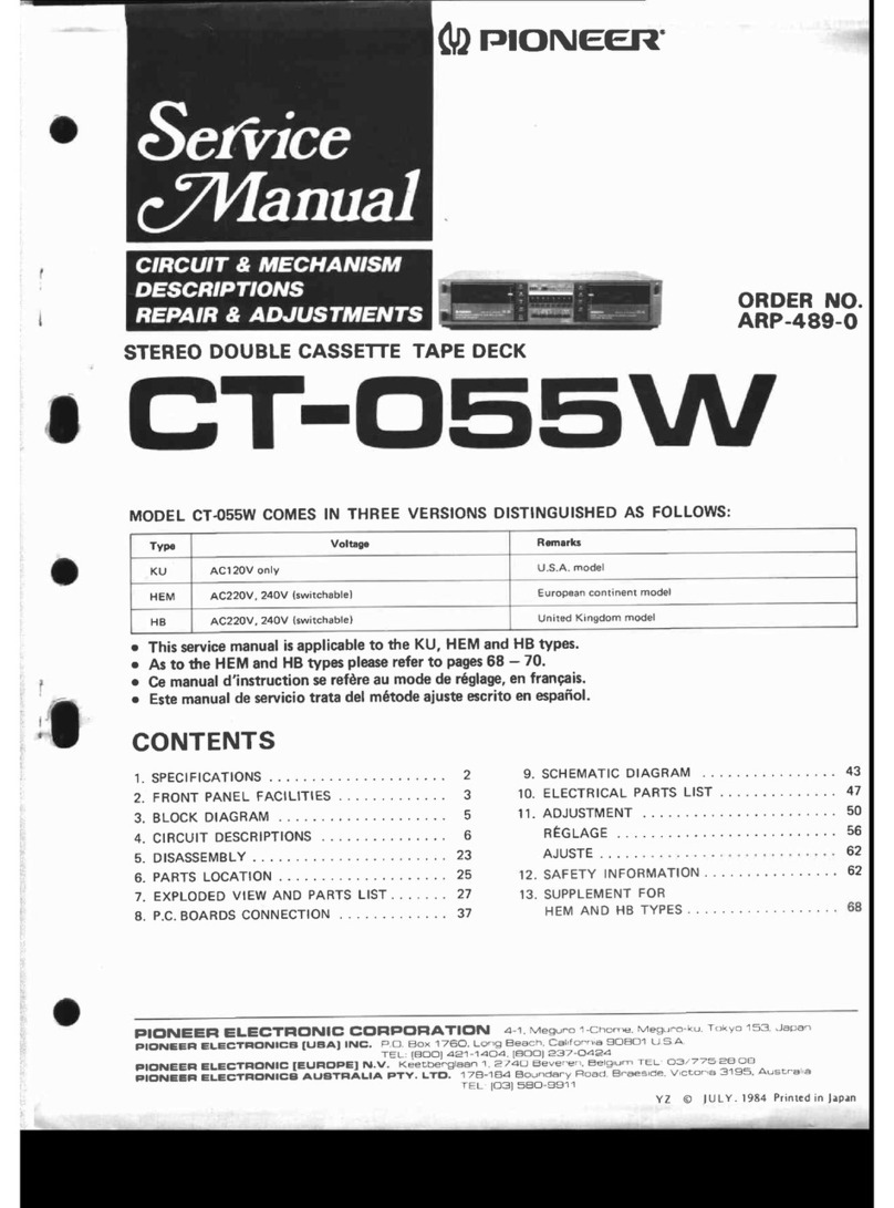
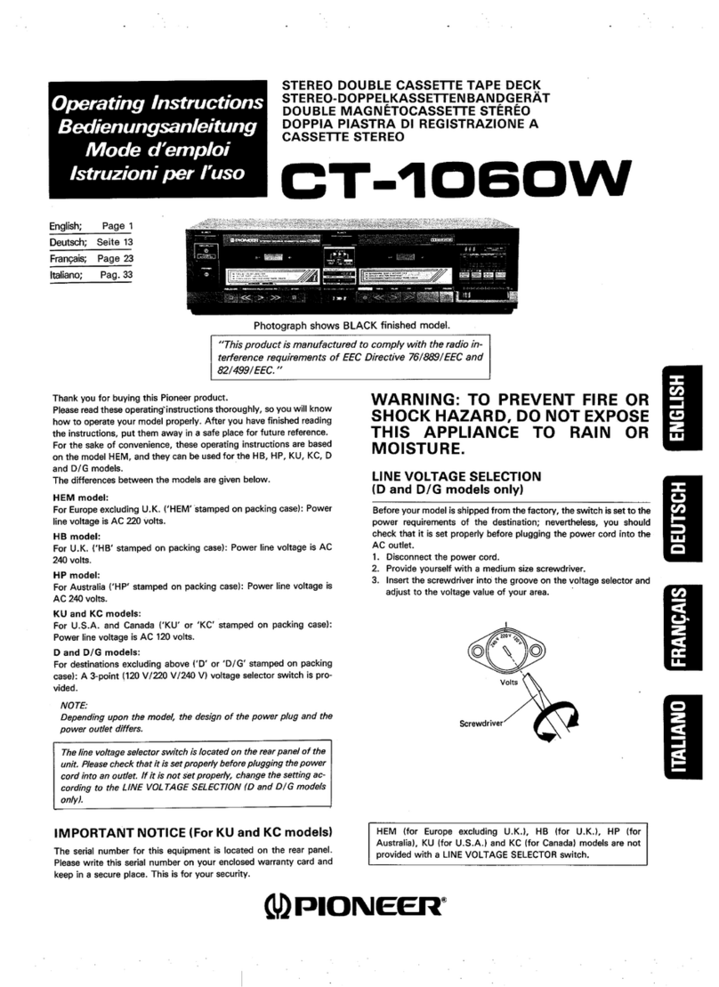
Pioneer CT-1040W User manual

d)
PIONEER’
PSY
st
44
ee
PAZ
ETIEY
REPAIR
&
ADJUSTMENTS
|
a
2
=
;
ORDER
NO.
—
ARP-
266-0
STEREO
DOUBLE
CASSETTE
TAPE
DECK
CT-ioqow
MODEL
CT-1040W
COMES
IN
SIX
VERSIONS
DISTINGUISHED
AS
FOLLOWS:
Voltage
Remarks
AC120V
only
U.S.A.
model
AC220V,
240V
(switchable)
European
continent
model
AC220V,
240V
(switchable)
United
Kingdom
model
AC220V,
240V
(switchable)
Australia
model
AC120V,
220V,
240V
(switchable)
General
export
model
AC120V,
220V,
240V
(switchable)
U.S.
Military
model
e
This
service
manual
is
applicable
to
the
CT-1040W/KU.
For
servicing
of
the
other
types,
please
refer
to
page
56.
e
For
the
circuit
and
mechanism
descriptions,
please
refer
to
the
CT-1040W,
CT-X8W
service
manual
(ARP-370).
e@
Ce
manuel
d’instruction
se
refére
au
mode
de
réglage,
en
francais.
Este
manuel
de
servicio
trata
del
método
de
ajuste
escrito
en
espafol.
CONTENTS
1.
SPECIFICATIONS
.............00
0000s
2
9.
ELECTRICALPARTS
LIST
...........---
31
2.
FRONT
PANEL
FACILITIES..............
3
10.
ADJUSTMENTS
.........2
020s
cree
ete
35
3.
DISASSEMBLY
.............
00000
eee
6
REGLAGE
4
ke
icc
es
ee
oe
ee
Pa
42
4.
PARTSLOCATION
.........
00002
e
eee
8
PMUS
TBs
des
fSedis
oars
haiti
owe
Reet
ae
49
5.
EXPLODED
VIEW
AND
PARTS
LIST........
10
11.
SAFETY
INFORMATION
....----
+0022
205
55
62.
PACKING
seis
ba
Sein
tae
ha
Wide
Be
SEE
20
12.
SUPPLEMENT
FOR
HE,
HB
AND
HP
TYPES
-
..
56
7.
P.C.
BOARD
CONNECTION
DIAGRAM
......
21
13.
SUPPLEMENT
FORD
ANDD/GTYPES...---
59
8.
SCHEMATIC
DIAGRAM......
lg
Ae
etnateardess
27
PIONEER
ELECTRONIC
CORPORATION
2-1.
Meguro
1-Chome,
Meguro-ku,
Tokyo
153,
Japan
PIONEER
ELECTRONICS
(USA)
INC.
1925
£.
Dominguez
St.,
Long
Beach,
California
30810
USA.
PIONEER
ELECTRONIC
[EUROPE]
N.V.
Keetbergiaan
1,
2740
Beveren,
Belgium
PIONEER
ELECTRONICS
AUSTRALIA
PTY.
LTD.
178-184
Boundary
Road,
Braeside,
Victoria
3195,
Australia

T-1040
W
1.
SPECIFICATIONS
SGishca
threaten
ceaae
sales
eel
Compact
cassette,
2-channel
stereo
“Hard
Permalloy”
recording/
playback
head
x
1
“Hard
Permalloy”
playback
head
x
1
“Ferrite”
erasing
head
x
1
‘Ferrite’
dummy
erasing
head
x
1
Motor
.........
PreeeeTESEESSESEEEOSEESEOSESOSE
2-speed
DC
servo
motor
x
2
Wow/
Flutter
........c:cccceeeeeeeeeeeeneees
No
more
than
0.045%
(WRMS)
No
more
than
+
0.17%
(DIN)
Fast
Winding
Time
.............0eceeeees
Approx.
110
seconds
(C-60
tape)
Frequency
Response
—
20
dB
recording:
Normal
tape
.........:ccceeeceseeeesenseee
eee
enereeneeeeeens
25
to
15,000
Hz
(35
to
14,000
Hz
+
3
dB)
CHroOMe@
tape
.isccecceccsvciscvstceserorcececvssdoceeasvecs
25
to
15,500
Hz
(35
to
15,000
Hz
+
3
dB)
Metal
tape
..........c
ce
cece
ese
ee
scence
neecueeneneeeeeaens
25
to
17,000
Hz
(35
to
16,500
Hz
+
3
dB)
Signal-to-Noise
Ratio
'
Dolby
NR
OFF
........cecceeeecceseeeseuceeesa
renee
seeeee
More
than
57
dB
Noise
Reduction
Effect
Dolby
type
B
NRON
............
...
More
than
10
dB
(at
5
kHz)
Harmonic
Distortion
..........:.ceeeeeeeseen
ees
No
more
than
1.0%
(0
dB)
Input
(Sensitivity)
MIG
(Ly
RY
ce
cisselieeatecadiniessanatienict
1.4
mV,
6mm
diam.
jack
(Source
impedance
11.7
kS2)
LINEINPUT):
fcéc
bisa.
ccsensseccieecac
ets cal
cetecti
acne
cess
Queess
50.7
mV
Output
(Reference
level)
LINE
(OUTPUT)
........cccccesceeeeeecnecesersceereeaeenaseneenerans
450
mV
(Output
impedance
2.8
kQ)
Headphones
...........cececceeceeeseeeeeeeeeeseeeeeeneeeeneeen
sees
0.25
mW
(Load
impedance
8
£2)
SUBFUNCTIONS
©
One-touch
recording
¢
Built-in
Dolby
B
type
noise
reduction
system
e
Full
electronic
auto-stop
mechanism
e
|C-based
full
logic
control
e
Headphones
jack
e
Auto
tape
selector
function
¢
Relay
play
function
for
continuous
playback
¢
Synchro
recording
start
function
¢
Tape
copying
function
(from
Deck
A
to
Deck
B)
¢
Pitch
control
function
(Deck
A)
¢
Automatic
music
search
function
(Deck
A)
e
Timer
standby
function
(Deck
B)
¢
REC
muting
function
*®
Double-speed
tape
copying
®
Phono
synchro
mechanism
(D
and
D/G
models
only)
e
Automatic
level
control
e
LED
level
meter
MISCELLANEOUS
Power
Requirements
KU,
KC
models
.............2.068
HE,
HB,
HP
models
..
eedeevaeuvcnetee
AC
120
V,
60
Hz
AC
220/240
V,
50/60
Hz
D,
D/Gmodels
...............
AC
120/220/240V,
50/60
Hz
(switchable)
Power
Consumption
KU,
KC
models
ices.
eds
cccccdessteivescaevawcocsidccr
es
otecenteecndegeve
28
watts
HE,
HB,
HP
models
.........2..ccceeseeeeneeeeerennenenseeeeeeneeaees
33
watts
D,
D/G
models
leaded
ites
ted
featicen
eae
estes
24
watts
Dimensions
..............ccseeeeeeeeeeene
420
(W)
x
101.5
(H)
x
315
(D)
mm
16-9/
16
(W)
x
4
(H)
x
12-6/16
(D)
in
Weight
(without
packaging)
............:ccesseeeeceeee
7.2
kg
(15
Ib
14
02)
FURNISHED
PARTS
Operating
instructions
.............
cee
ceeeeeeeeeenececnseeeeevnecnraneenaseease
Connection
cord
with
pin
plug
NOTES:
1.
Reference
Tapes:
Normal
&
LH:
DIN
44513/BLATTE
or
equiv.
CrO,
DIN
45513/BLATT7
(CrO,)
or
equiv.
2.
Reference
Recording
Level:
Meter
0
dB
indicating
level
(160
nwb/m
magnetic
level
=
Philips
cassette
reference
level)
Reference
Signal:
315
Hz
4.
Wow
&
Flutter:
©
JIS
(3
kHz,
with
acoustic
compensation
(weighted)
rms
value);
DIN
3,150Hz
with
acoustic
compensation
tion
(weighted)
PEAK
value
DIN
45507
5.
Frequency
Response:
¢
Measured
at
—
20
dB
level,
DOLBY
NR
OFF,
level
deviation
is
+
6
dB
without
indication.
6.
Signal-to-Noise
Ratio:
¢
Measured
at
3rd
harmonic
distortion
3%
level,
weighted
(DIN
45513/BLATT7)
7.
Sensitivity:
Input
level
(mV)
required
for
reference
recording
level!
with
input
(REC)
level
contro!
set
to
maximum
8.
Maximum
Allowable
Input:
While
decreasing
settings
of
input
(REC)
level
controls
and
increasing
level
at
input
jacks,
this
is
the
maximum
input
level
(mV)
at
the
point
where
recording
amplifier
OUTPUT
waveform
becomes
clipped.
9.
Reference
Output
Level:
Playback
output
level
when
meter
in-
dicates
0
dB.
10.
This
model
does
not
employ
a
recording/playback
connector
(DIN-type).
NOTE:
Specifications
and
the
design
are
subject
to
possible
modificatins
without
notice
due
to
improvements.
hod
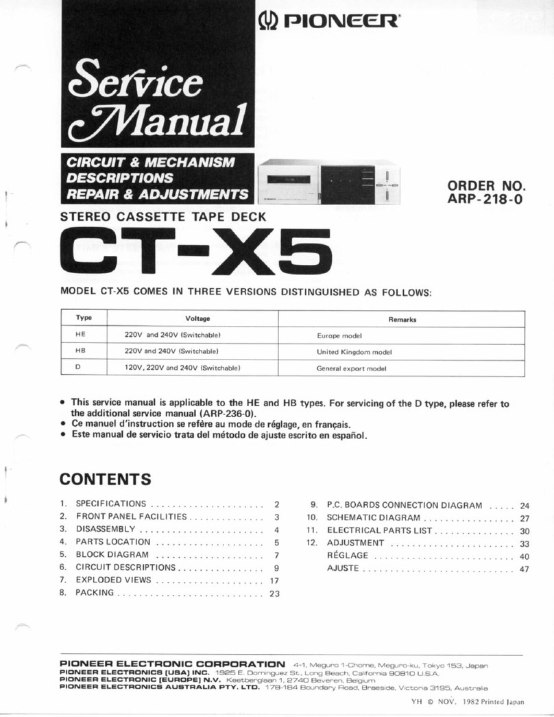
2.
FRONT
PANEL
FACILITIES
DEEK'B
(for
recording
and
playback)
12
3
®
PIONEER
STEREO
DOUBLE
CASSETTE
QECK
CT:1040W
@
POWER
SWITCH
The
power
is
switched
on
when
this
switch
is
pressed
to
the
‘‘in’”’
position.
Release
the
switch
to
turn
off
the
power.
¢
After
the
switch
is
set
to
the
ON
position,
the
muting
circuit
is
activated
and
so
the
unit
will
not
operate
for
about
4
seconds.
«
When
the
POWER
switch
is
set
to
OFF
while
the
tape
deck
is
operating,
the
operational
mode
is
released
and
the
unit
is
set
to
the
stop
mode.
*
When
the
POWER
switch
is
set
to
ON
while
the
TIMER
switch
is
at
the
REC
or
PLAY
position,
the
recording
or
playback
mode
is
established
automatically.
Make
sure
that
the
TIMER
switch
is
at
OFF
when
an
unattended
recording
or
wake-up
playback
opera-
tion
is
not
to
be
performed.
@
TIMER
START
SWITCH
This
is
operated
for
unattended
recording
or
wake-up
playback
us-
ing
an
optional
audio
timer.
Timer
playback/recording
is
a
function
of
Deck
B.
Deck
A
cannot
be
used
for
timer
playback/recording.
PLAY:
Set
here
so
that
the
unit’s
power
is
switched
on
at
the
time
preset
on
the
audio
timer
and
so
that
the
unit
is
automatically
set
to
the
playback
mode.
OFF:
Set
here
when
the
audio
timer
is
not
being
used.
REC:
Set
here
so
that
the
unit's
power
is
switched
on
at
the
timer
preset
on
the
audio
timer
and
so
that
the
unit
is
automatically
set
to
the
recording
mode.
©
EJECT
BUTTON
The
cassette
door
opens
when
this
button
is
pressed.
Do
not
press
it
when
the
tape
is
traveling
or
while
the
recording
or
playback
mode
has
been
temporarily
suspended.
©
AUTO
APF
SELECTOR
cr
spe
COPY
@
RELAY
Lay
RP
@
svncrmo
rec
stant
4
17
OO
fpasy
xa]
@
PLAY
SWITCH
(>)
Depress
this
switch
to
playback
a
tape.
@
STOP
SWITCH
(@)
Depress
this
switch
to
stop
the
tape
travel
and
to
release
the
operating
switches.
@
REW
SWITCH
(<<)
Depress
this
switch
to
rewind
the
tape
at
high
speed
(The
tape
will
travel
from
right
to
left).
@
PAUSE
SWITCH
Press
to
temporarily
stop
the
tape
transport
in
the
playback
or
recor-
ding
mode.
At
times
like
this,
the
pause
indicator
(BE)
lights.
When
pressed
again,
the
pause
function
is
released
and
the
tape
starts
to
travel
again.
The
switch
does
not
function
in
the
fast
forward
or
re-
wind
modes.
When
it
is
pressed
in
the
stop
mode,
the
pause
in-
dicator
lights;
when
it
is
pressed
again,
the
unit
is
reset
to
the
stop
mode
and
the
tape
does
not
move.
@
REC/REC
MUTE
SWITCH
This
switch
functions
as
both
the
recording
switch
and
record
muting
switch.
When
pressed,
the
unit
is
set
to
the
recording
mode
and
when
it
is
kept
depressed,
it
functions
as
the
recording
mute
switch.
Recording
switch’:
Press
the
switch
when
recording
sound
onto
the
tape.
The
REC
(@)
indicator
now
lights.
If
the
accidental
erasure
prevention
tabs
on
the
cassette
shell
have
been
broken
out
or
the
tape
has
not
been
loaded,
the
unit
will
not
be
set
to
the
recording
mode
even
if
this
switch
is
pressed.
Press
the
stop
switch
(Ml)
to
release
the
recording
mode.
When
this
switch
is
pressed
during
recording,
unrecorded
blanks
can
be
created
for
as
long
as
the
switch
is
kept
depressed.
While
depressed,
the
REC
MUTE
indicator
(
©
)
lights.
Use
this
switch
for
efficient
editing
of
tapes
with
sufficient
blanks
between
the
pro-
grams
and
for
providing
the
unrecorded
blanks
which
are
required
to
operate
the
index
scan,
music
search/skip,
music
repeat
and
blank
search
accessory
functions.
©
FF
SWITCH
(>>)
Depress
this
switch
to
send
the
tape
forward
at
high
speed
(The
tape
will
travel
from
left
to
right).
@
LEVEL
METERS
These
indicate
the
input
level
during
recording
and
the
output
level
during
playback.
@
PAUSE
INDICATOR
(If)
This
lights
when
the
unit
is
set
to
the
pause
mode.
@
RECORDING
INDICATOR
(@)
This
lights
when
the
unit
is
set
to
the
recording
mode.
@
RECORDING
MUTE
INDICATOR
(0)
This
lights
while
the
REC
MUTE
switch
is
pressed
during
a
recor-
ding.
@
MUSIC
SEARCH
SWITCH
(MS)
Use
this
switch
when
playing
a
tape
with
music
recorded
on
it
to
quickly
locate
the
beginning
of
songs
separated
by
a
non-recorded
section
of
over
4
seconds
duration.
In
the
fast-forward
mode
or
re-
wind
mode,
when
this
switch
is
set
to
ON,
tape
travel
will
stop
in
the
non-recorded
area
between
songs
and
the
unit
is
automatically
set
to
the
playback
mode.
This
is
a
handy
function
for
locating
the
pro-
gram.
The
music
search
function
belongs
to
Deck
A.
@®
SET
SWITCH
Press
this
switch
to
skip
programs
on
a
tape
when
searching
for
the
program
you
want
to
hear.
When
it
is
pressed
by
a
number
of
times
equivalent
to
the
number
of
programs
which
are
to
be
skipped
on
the
tape,
this
number
is
displayed
on
the
set
indicator.
@
MS
SET
INDICATOR
The
number
of
programs
on
the
tape
to
be
skipped
is
indicated
here.
When
the
MS
SET
switch
is
pressed,
a
number
not
exceeding
‘'9”
appears
on
this
indicator.
CT-
1040
W
@
PITCH
CONTROL
This
can
be
used
to
vary
the
tape
speed
of
Deck
A
across
a
+
6%
range.
The
speed
increases
when
the
control
is
rotated
clockwise
(())
and
reduced
when
rotated
counterclockwise
|
Q));
the
musical
intervals
are
made
higher
or
lower,
respectively.
The
stan-
dard
speed
is
obtained
at
the
control's
center
clickstop
position
(¥).
Use
the
contro!
to
adjust
the
speed
when
adjusting
the
intervals
with
mixing
recording
or
playback
or
when
playing
back
a
tape
recorded
on
another
tape
deck
on
your
own
deck.
@
TAPE
COUNTER
This
indicates
the
transport
position
of
the
tape
loaded
in
Deck
B
with
a
3-digit
number.
@
RESET
BUTTON
Depressing
this
button
resets
the
tape
counter
to
000’.
Depress
this
button
before
recording
or
playback
to
reset
the
counter
to
000’.
If
you
make
a
memo
of
the
tape
contents
and
corresponding
tape
counter
numbers
during
recording
and
playback,
you
will
have
an
index
of
the
programs
on
the
tape
enabling
you
to
conveniently
find
any
desired
program
on
the
tape.
@
COPY
SWITCH
“Copying”
refers
to
the
process
of
transferring
the
recorded
con-
tents
on
a
pre-recorded
tape
onto
another
tape.
The
pre-recorded
tape
is
loaded
into
Deck
A
and
its
contents
are
recorded
onto
Deck
B
when
this
switch
is
pressed.
When
the
switch
is
pressed,
the
®
indicator
lights.
Tape
copying
cannot
be
performed
from
Deck
B
to
Deck
A.
@
HIGH
SPEED
SWITCH
This
switch
is
used
to
select
normal
tape
speed
or
double
tape
speed
for
tape
copying.
The
@
indicator
lights
up
to
indicate
double
speed.
Release
the
switch
when
copying
tapes
at
the
normal
tape
speed.
@
RELAY
PLAY
SWITCH
Press
this
switch
for
relay
play.
When
pressed,
the
@
indicator
lights.
When
the
tape
loaded
in
one
deck
has
finished
playing
and
the
tape
comes
to
the
end,
the
tape
in
the
other
deck
automatically
starts
playback.
Relay
play
is
possible
from
Deck
A
to
Deck
B
and
vice
versa.
@
SYNCHRO
REC
START
SWITCH
The
playback
tape
is
loaded
into
Deck
A
while
the
recording
tape
is
loaded
into
Deck
B.
When
this
switch
is
pressed,
Deck
A
is
automatically
set
to
the
playback
mode
and
Deck
B
is
automatically
set
to
the
recording
mode,
and
the
tapes
start to
move
simultaneously.
Use
this
switch
for
tape
copying.

‘CT-1040
Ww
@
RECORDING
LEVEL
CONTROL
This
control
is
used
to
adjust
the
input
from
the
rear
panel
REC
ter-
minals
and
the
MIC
jack.
When
rotated
clockwise
(
(}
),
the
recor-
ding
level
is
increased;
when
rotated
counterclockwise
()),
the
level
is
reduced.
The
standard
input
level
is
obtained
when
the
con-
trol
is
set
to
the
center
clickstop
position
(¥).
@®
*DOLBY
NR
SWITCH
Press
this
switch
to
the
ON
(
m=.
)
position
when
recording
material
with
the
Dolby
noise
reduction
system
or
when
playing
back
a
tape
which
has
been
recorded
with
the
system.
Release
the
switch
to
the
OFF
(
Hl
)
position
when
recording
material
without
the
Dolby
system
or
when
playing
back
a
tape
which
has
not
been
recorded
with
the
system.
voi
oT
*The
word
“Dolby”
and
DO]
are
trademarks
of
Dolby
Laboratories
Licensing
Corporation.
Noise
Reduction
System
manufactured
under
license
from
Dolby
Laboratories
Licensing
Corporation.
@
PHONES
SWITCH
While
a
tape
is
playing
back
in
Deck
B,
the
programs
played
back
on
Deck
A
can
be
heard
through
headphones.
This
function
is
used
when
preparing
the
next
program
for
your
friends
to
sing
along
with,
for
instance.
Refer
to
the
table
for
the
rear
panel
PLAY
ter-
minal
output
with
Deck
A
and
Deck
B
playback
and
for
the
head-
phone
jack
output
when
the
phones
switch
is
selected.
GHA
MS
&
PLAY BACK
8
SYNCED
BEC
START
beecon
(@eay)
PHONES PHONES
DECK
A
|
DECK
B
TERMINAL
SWITCH
JACK
_|__
OUTPUT
POSITION
OUTPUT
Playback
|
Playback
|
Deck
B
output
A
or
B
(
Ml
)
|
Deck
B
output
Playback
|
Playback
|
Deck
B
output
Playback
|
_
A
(
mm)
|
Deck
A
output
A
or
B{
BB)
|
Deck
A
output
Deck
A
output
Playback
—
Deck
A
output
A
(
m)
-
_
Playback
|
Deck
B
output
A
or
B(
BB)
|
Deck
B
output
Playback
@
MIC
JACKS
These
are
the
input
jacks
for
microphone
recording.
Plug
the
left
channel
microphone
into
the
L
jack
and
the
right
channel
microphone
into
the
R
jack.
@
HEADPHONE
JACK
This
is
the
output
jack
for
the
stereo
headphones.
Plug
the
head-
phones
into
this
jack
to
monitor
the
quality
of
a
recording
or
to
listen
to
a
tape
privately.
NOTE:
Use
headphones
with
a
low
impedance.
Sufficient
volume
will
not
be
obtained
with
high-impedance
headphones.
@®
COPY
INDICATOR
This
lights
when
the
COPY
switch
is
pressed.
@
HIGH
SPEED
INDICATOR
This
fights
when
the
HIGH
SPEED
switch
and
COPY
switch
are
pressed.
@
RELAY
PLAY
INDICATOR
This
lights
when
the
RELAY
PLAY
switch
is
pressed.
Deck
B
output
3.
DISASSEMBLY
Front
panei
assembiy
Operation
switch
B
assembly
Fig.
3-1
Disassembly
Control
assembly
<A
Ke
Eo
Sensor
R/P
S
ge
<9
assembly
Sensor
P
assembly
Operation
switch
A
assernbly

CT-
1040
W
Disassembly
Procedures
1.
Undo
screws
@
to
remove
the
bonnet.
2.
Undo
screws
@
,
and
using
a
screwdriver
push
panel
stay
hooks
A
(four
positions
along
the
top)
and
hooks
B
(two
positions
along
the
bottom)
to
remove
the
front
panel
assembly.
3.
Undo
screws
©
to
open
the
control
unit
and
expose
the
adjustment
locations.
4.
Undo
screws
@
to
remove
the
stay.
5.
Undo
screws
@
to
remove
the
counter.
6.
Pull
push-knobs
A,
B
and
C
forward
and
undo
screws
@
to
remove
the
panel
stay.
7.
Undo
screws
@
and
disengage
the
hook
to
remove
the
operation
switch
A
unit.
8.
Undo
screws
@
and
@
to
remove
the
me-
chanism
units
(deck
A
and
deck
B).

4
cT-1040
w
4.
PARTS
LOCATION
e
Parts
without
part
number
cannot
be
supplied.
e
The
/A\
mark
found
on
some
component
parts
indicates
the
importance
of
the
safety
factor
of
the
part.
Therefore,
when
replacing,
be
sure
to
use
parts
of
identical
designation.
e
For
your
Parts
Stock
Control,
the
fast
moving
items
are
indicated
with
the
marks
wk
and
*.
wk
GENERALLY
MOVES
FASTER
THAN
*.
Front
Panel
View
This
classification
shall
be
adjusted
by
each
distributor
because
it
depends
on
model
number,
temperature,
humidity,
etc.
Push
knob
B
(HIGH
SPEED)
RAC-322
Push
knob
C
(RELAY
PLAY,
SYNCHRO
REC)
RAC-320
Push
knob
A
(COPY)
RAC-321
Operation
knob
B
assembly
(STOP)
RXB-776
Operation
knob
B
assembly
(STOP)
RXB-776
Bonnet
RNA-600
*k
Door
B
wk
RNL-686
a
Ber
aie
et
|
~~
RNL-685
Eject
knob
asembly
——
=
od
:
:
fee
——---———
Eject
knob
assembly
RXB-774
-
Ss
=
“|
RXB-774
Standby
knob
Ss
RAC-342
—
PC
knob
(PITCH)
Power
knob
assembly
RAC-297
RXB-781
Operation
knob
D
assembly
(PAUSE)
RXB-778
Set
knob
(SET)
RAC-319
MS
knob
(NS)
Operation
knob
E
assembly
(REC/REC
MUTE)
RAC-318
RXB-779
Push
knob
E
(PHONES)
RAC-324
VR
knob
RAC-298
Push
knob
D
(DOLBY
NR)
RAC-323
Front
View
with
Front
Panel
Removed
Variable
resistor
20k-A
(REC
LEVEL
)
RCV-109
Counter
RAW-196
Operation
knob
A
assembly
(PLAY)
RXB-775
operation
knob
A
assembly
(PLAY)
RXB-775
Music
search
assembl;
B
RWX-710
Cassette
plate
Cassette
pate
RAH-441
RAH-441
*
Erase
head
REC/PB
had
RPB-085
RPB-097
(RPB-091}
wk
~REC/PB
head
Erase
had
RPB-097
RPB-085
(RPB-091)
MS
set
cover
assem
y
Level
meter
assembly
RXB-780
RAW-194
Operation
knob
C
assembly
(REW/tF}
Operation
knob
C
assembly
(REW/F
F)
RXB-777
RXB-777
Headphone
jock
MIC
jack
RKN-081
RKN-080
8

CT-
1040
W
Top
View
with
Bonnet
Removed
Main
assembly
A\
®
Power
transformer
(120V)
RTT-333
Power
switch
assembly
Control
bi
ontrol
assembly
/A\
*&*Power
switch
RSA-060
/A\
*®
Motor
assembly
RXM-104
Terminal
assembly
(B)
Rear
Panel
View
A\Strain
relief
fEC-395
4P
pin
jack
|
J\tower
cord
RKB-020
RD
G-048

T-10490
W
5.
EXPLODED
VIEW
AND
PARTS
LIST
5.1
MAIN
e
Parts
without
part
number
cannot
be
supplied.
e
The
/A\
mark
found
on
some
component
parts
indicates
the
importance
of
the
safety
factor
of
the
part.
Therefore,
when
replacing,
be
sure
to
use
parts
of
identical
designation.
e
For
your
Parts
Stock
Control,
the
fast
moving
items
are
indicated
with
the
marks
wk
and
*.
wk
GENERALLY
MOVES
FASTER
THAN
*.
This
classification
shall
be
adjusted
by
each
distributor
because
it
depends
on
model
number,
temperature,
humidity,
etc.
Mark
No.
Part
No.
Description
Mark
No.
Part
No.
Description
1.
RBM-002
Nylon
rivet
36.
RAC-324
Push
knob
E
2,
RBH-989
Operation
spring
37.
RXB-781
Power
knob
assembly
3.
RBH-990
Eject
spring
38.
RKP-854
Connector
assembly
5P
4,
RXB-772
Sensing
holder
assembly
39.
REC-369
Foot
assembly
5.
RBF-062
Washer
40.
RBA-081
Screw
6.
RNL-755
Sensing
pully
41.
RKB-020
4P
pin
jack
7.
RAW-196
Counter
42.
RKP-804
Connector
assembly
12P
8.
RAW-194
Level
meter
assembly
43.
RSG-152
Push
switch
assembly
9,
RWX-710
Music
search
assembly
B
44,
RKP-803
Connector
assembly
13P
A
*
10.
RTT-333
Power
transformer
(120V)
45.
RKP-814
Connector
assembly
2P
A
*
11.
RDG-048
Power
cord
46.
RKP-747
Board
in
connector
3P
A
12,
REC-395
Strain
relief
47.
RKP-748
Board
in
connector
3P
13,
RXX-402
Front
panel
assembly
48.
RKP-749
Board
in
connector
3P
14.
RNL-684
Lens
49.
RKN-081
Headphones
jack
15.
REE-081
Paper
50.
RKN-080
MIC
jack
16.
RAH-441
Cassette
plate
51.
RKP-750
Connector
assembly
5P
17.
RNA-600
Bonnet
52.
RKP-751
Connector
assembly
3P
18.
RXB-774
Eject
knob
assembly
53.
RNL-610
LED
holder
19,
RAC-342
Standby
knob
54.
RSG-063
Operation
switch
20,
RNL-685
Door
A
55.
RSG-143
Push
switch
21:
“RNE-686
Deore
56.
RSG-150
Push
switch
22.
RXB-775
Operation
knob
A
assembly
57.
RSG-153
Push
switch
.
rey
58.
RKP-812
Connector
assembly
3P
23.
RXB-776
Operation
knob
B
assembly
59.
RKP-811
Connector
assembly
3P
(STOP)
60.
RKP-754
Connector
assembly
4P
24.
RXB-777
Operation
knob
C
assembly
(REW/F
F)
61.
RKP-810
Connector
assembly
3P
25.
RXB-778
Operation
knob
D
assembly
*
62.
BG5524S
LED
(PAUSE)
*
63.
PR5524S
LED
26.
RXB-779
0
donnane
.
64.
RKP-809
Connector
assembly
4P
;
:
PErSdOn
ROD
=
assenoly
*
65.
RCV-109
iable
resistor
20k-A
(REC/REC
MUTE)
Variable
resistor
pleads
Mecaek
Gover
aseerny
66.
RKP-760
Connector
assembly
3P
28.
RAC
S19
See
nae
67.
RKP-761
Connector
assembly
3P
28,
RAG
821
Pose
Knob
A
*
68.
RCS-026
Variable
resistor
1k-B
a0:
RAC
322
Push
knee:
©
*
69.
GP-411B
Photo
interrupter
70.
RKP-808
Connector
assembly
4P
31,
RAC-320
Push
knob
C
82.
BOC
Sae
push
ene
2
71.
RKP-813
Connector
assembly
3P
Se
S16
MS
nee
wk
=
72.
RSH-064
Slide
switch
eu
RAC
22
VOD
73.
RKP-833
Connector
assembly
3P
Soe
RAC
AaE
es
wk
=
74,
28D
1265
Transistor
Awe
75.
-RSA-060
Power
switch
10

Mark
No.
Part
No.
Description
76.
RKP-834
Connector
assembly
6P
77,
RKP-774
Connector
assembly
5P
78.
RKP-775
Connector
assembly
79.
RKP-807
Connector
assembly
7P
80.
BBZ30P080FZK
Screw
81.
VBZ40POG60FMC
Screw
82.
VBZ26PO60FMC
Screw
83.
PMZ26PO040FMC
Screw
84.
BMZ30PO60FMC
Screw
85.
RKP-520
Connector
assembly
3P
86.
RKP-684
Connector
assembly
2P
87.
RKP-709
Connector
assembly
4P
88.
RKP-298
Connector
assembly
6P
89.
RKP-769
Connector
assembly
7P
90.
RKP-770
Connector
assembly
8P
91.
AEK-073
Fuse
(1,25A)
101.
Mechanism
unit
(Deck
A)
102.
Mechanism
Unit
(Deck
B)
103.
Main
chassis
104.
Bottom
plate
105.
Stay
106.
Panel
stay
107.
108.
P.C.B.
stud
109.
Panei
hinge
110.
Connector
assembly
2P
Mark
No.
111.
112,
113.
114.
115.
116.
117.
118.
119.
120.
121.
122.
123.
124,
125.
126.
127.
128.
129.
130.
Part
No.
Description
Spacer
Connector
assembly
2P
Connector
assembly
2P
Connector
assembly
2P
Connector
assembly
2P
Main
assembly
Jack
assembly
Operation
switch
A
assembly
Operation
switch
B
assembly
VR
assembly
Pitch
control
assembly
Sensor
P
assembly
Sensor
R/P
assembly
Timer
switch
assembly
Transistor
A
assembly
Transistor
B
assembly
Control
assembly
Power
switch
assembly
11

r
assembly
2P
r
assembly
2P
r
assembly
2P
r
assembly
2P
nbly
nbly
switch
A
assembly
switch
B
assembly
bly
rol
assembly
issembly
P
assembly
tch
assembly
A
assembly
B
assembly
sembly
tch
assembly
CT-1090
W

=
1
|
5.3
MECHANISM
UNIT
(DECK
B)
Parts
Mark
_
+
*
*
*
*
be>>>

A
Parts
list
of
Mechanism
unit
(Deck
A)
Mark
16
No.
Part
No.
1.
RNL-527
2.
RXB-716
3.
RBH-865
4.
RNL-523
5.
RBH-794
6.
RBH-723
7.
RNF-989
8.
RX8B-720
9.
RBH-890
10.
RNL-524
11.
RNH-219
12.
RBH-948
13.
RBH-983
14.
RBH-949
15.
RNL-261
16.
RNL-534
17.
REB-447
18.
RNL-685
19.
RNL-569
20.
RBK-175
21.
RWX-710
22.
RXB-849
23.
RNK-998
24.
RXB-714
25.
WA21D040D025
26.
RXB-715
27.
RXB-374
28.
RNK-999
29.
WA17D032D025
30.
RBK-724
31.
RXB-376
32.
YS20FBT
33.
RBH-727
34.
RBH-725
35.
WA17D032D025
36.
RNL-047
37.
RXB-723
38.
RBH-842
39.
RNL-059
40.
RNL-051
41.
RBH-722
42.
RXB-717
43.
RBH-980
44.
REB-488
45.
REB-495
46.
REB-355
47.
RBF-050
48.
RBH-778
49.
RLB-390
50.
RBA-069
Description
Reference
pin
Metal
holder
assembly
HB
return
spring
Sub
head
base
HB
drive
spring
Head
adjust spring
Spacer
Pinch
arm
assembly
Pinch
pressure
spring
Half
holder
Half
spring
Lock
spring
Eject
spring
Lever
spring
Cylinder
Piston
O
ring
Door
A
Pocket
Pocket
spring
Music
search
assembly
B
Reel
base
assembly
Idler
gear
Supply
reel
base
assembly
Washer
TU
reel
base
assembly
Idler
arm
assembly
TU
idler
Washer
Idler
pressure
spring
Drive
arm
full
assembly
Washer
Braket
spring
FR
spring
Washer
Solenoid
arm
Lever
assembly
Lever
spring
Cam
gear
Gear
lever
Gear
lever
return
spring
Flywheel assembly
Arm
spring
Capstan
belt
Drive
belt
Sensing
belt
Oil
stop
washer
Return
spring
Stopper
Screw
M3
x7
Mark
No.
Part
No.
Description
A
*
51.
RXP-134
Plunger
solenoid
P
A
*&
52.
RXP-135
Plunger
solenoid
F
A
*
=
53.
RXP-136
Plunger
solenoid
R
A
*
54.
~RXM-104
Motor
assembly
A
*®
=
55.
~RXP-137
Plunger
solenoid
(PMS)
ik
56.
RSN-010
Lever
switch
57.
RPB-085
Erase
head
58.
RPB-097
REC/PB
head
(RPB-091)
59.
RKP-520
Connector
assembly
3P
60.
RBM-002
Nylon
rivet
3
x
8
61.
YE30FUC
Washer
62.
YS30FBT
Washer
63.
VCZ26PO90FMC
Screw
64.
VCZ26POG60FMC
Screw
65.
YE40FUC
Washer
66.
PMZ20P150FMC
Screw
67.
IMZ20Y150FMC
Screw
68.
PMZ26PO60FMC
Screw
69.
PMX26PO30FMC
Screw
70.
YE20FUC
Washer
71.
PMA26P040F
MC
Screw
72,
PM2Z20P080FMC
Screw
73.
RBA-081
Screw
101.
Chassis
assembly
102.
Head
bass
103.
Shaft
stopper
104.
Side
plate
L
assembly
105.
Spacer
106.
Cr
02
detect
lever
A
107.
Side
plate
R
108.
Lock
lever
109.
Eject
lever
110.
Brake
plate
111,
Brake
shoe
112.
Solenoid
bracket
R
113.
Solenoid
bracket
F
114,
Side
arm
115.
Eject
plate
A
116.
P.C.B.
holder
117.
Attachment
plate
A
118.
Fiywheel
holder
119.
Thrust
receptacle
120.
PMS
plate
421.
Stopper
lever
122.
Terminal
unit
(A)
423.
Cord
holder
124,
Binder
125.
Connector
assembly
2P

L
Parts
list
o1
Mark
CT-10490
W
|
5.2
MECHANISM
UNIT
(DECK
A)
2
©OND
TEwWN=
\5
*
s
o

63
18
A
Parts
list
of
Mechanism
unit
(Deck
B)
Mark
__
No.
__Part
No.
Description
6
s
Mark
No.
Part
No.
Description
*
51.
RSN-010
Lever
switch
wk
52.
RSH-058
Stide
switch
1.
RNL-527
Reference
pin
53.
RPB-085
Erase
head
2.
RXB-716
Metal
holder
assembly
54.
RPB-097
REC/PB
head
3.
RBH-865
HB
return
spring
(RPB-091)
4.
RBH-794
HB
drive
spring
55.
RNH-184
5.
RBH-723
Head
adjust
spring
:
56.
RKP-298
Connector
assembly
6P
6.
RNF-989
Spacer
57.
RKP-526
Connector
assembly
2P
7.
RXB-871
Pinch
arm
assembly
58.
RNL-523
Sub
head
base
8.
RBH-890
Pinch
pressure
spring
59.
YE30FUC
Washer
9.
RNL-524
Half
hoider
60.
YS30FBT
Washer
10.
RNH-219
Half
spring
61.
VCZ26POS0FMC
Screw
11,
RNL-529
REC
detect
lever
62.
PMZ26P100FMC
Screw
12.
RBH-948
Lock
spring
63.
VCZ26PO60FMC
Screw
13.
RBH-983
Eject
spring
A
64.
YE40FUC
Washer
14,
RBH-949
Lever
spring
65.
PMZ20P150FMC
Screw
15.
RNL-261
Cylinder
66.
IMZ20Y150FMC
Screw
16.
RNL-534
Piston
67.
PMZ26PO60FMC
Screw
17,
REB-447
O
ring
68.
PMX26PO30FMC
Screw
18.
RNL-569
Pocket
69.
YE20FUC
Washer
19.
RBK-175
Pocket
spring
70.
PMA26P040FMC
Screw
20.
RNL-686
Door
B
71.
RBA-081
Screw
21.
RXB-849
Reel base
assembly
72.
RBM-002
Nylon
rivet
3x
8
22.
RNK-998
Idler
gear
73.
23.
RXB-714
Supply
reel
base
assembly
74.
REB-493
Counter
belt
}
24.
WA21D040D025
~—-
Washer
75.
RNL-047
Solenoid
arm
25.
RXB-715
TU
reel
base
assembly
R
76.
RAW-194
Level
meter
assembly
26.
RXB-374
Idler
arm
assembly
27.
RNK-999
TU
idler
28.
WA17D032D025
Washer
5
29.
RBK-724
idler
pressure
spring
101,
Chassis
assembly
30.
RXB-376
Drive
arm
Full
assembly
102.
Head
bass
103
Shaft
stopper
31.
YS20FBT
Washer
104.
Side
plate
L
assembly
32.
RBH-727
Brake
spring
105.
Metal
detect
lever
33.
RBH-725
FR
spring
34.
WA170032D025
Washer
106.
CrO2
detect
lever
35.
RXB-723
—
Lever
assembly
107.
Side
plate
R
108.
Lock
lever
36.
RBH-842
Lever
spring
109.
Eject
lever
37.
RNL-059
Cam
gear
110.
Brake
plate
38.
RNL-051
Gear
lever
39.
RBH-722
Gear
lever
return
spring
111.
Brake
shoe
40.
RXB-717
Flywheel
assembly
112.
113.
Slide
arm
41.
RBH-980
Arm
spring
114,
Eject
plate
B
*
42,
REB-488
Capstan
belt
115,
P.C.B.
holder
*
43.
REB-495
Drive
belt
44,
RBF-050
Oil
stop
washer
116.
Attachment
plate
B
45.
RBH-778
Return
spring
117.
Flywheel
holder
118.
Thrust
receptacle
46.
RBA-069
Screw
M3
x
7
119.
PMS
plate
Aw
47.
RXP-134
Plunger
solenoid
P
120.
Terminal
unit
(B)
A®
48.
RXP-135
Plunger
solenoid
F
A*®
49.
RXP-136
Plunger
solenoid
R
121.
Connector
assembly
4P
Av*
~~
50.
RXM-104
Motor
assembly
122.
Solenoid
bracket
R
123.
Solenoid
bracket
L
193
Mark
PACKING
CT-104900
w
No.
Part
No.
1.
RHA-254
2.
RRB-219
3.
RDE-010
4.
RHG-630
101.
102.
Description
Pad
Operating
instructions
Connection
cord
assembly
Packing
case
Paper
Paper
20

C
CT-
1040
W
2
3
A
|
5
6
7.
P.C.BOARDS
CONNECTION
DIAGRAM
TRANSISTOR
MECHANISM
’
UNIT(A)
(4/2)
MAIN
ASS’°Y
RWX-792
i
ke
Qi05
aioe
Q103
Q102
Q205
Q206
Q404
0403
Q308
0408
ICTIO
104
1c704
Q203 Q202
'C702
304,
303,
Ic704
Q307
305
0306
0406
405
@407
Q7i2
cr02
:
Cc
201
@301
703
Q402
C707
Q104
1C708
NORM
Q703
Q401
Q3i0__—Ic304
IC4o1
Q204
1¢705
.
METAL
2
VRION
Ve50,
VR70I
VR404
VR304
i
vR201
VRSON
|
TP.2
TRA
$2201
{
: :
$2204:
DECK
A
TAPE
SELECTOR
J
RSN
-
040
|
PLAYBACK
HEAD
RPB-O97
or
RPB-O91
R
CH
ip
:
L
CH
REC/P.B
HEAD
RPB-O97
or
RPB-094
R
CH
VR
ASSY
JACK
ASS’Y
RWX-
793
1C301,401
IR2C30
Q101%.
106,201~
206,30i.310,
708
2SD880
0302,402
{K60AUF
ZD703
RD6.2E82
1c701,703
MS220L
Q401~
410,704,705
Q7412
©
28¢2673
0701,703
182Z1-LC2
20704
RD4.3EB2
0
1C702,704,706
MS5218L
2SC1740LN
D301,303~
306,404
0702,704
i82CI-
LC2
1c705
HAN226
9702
,703
,706
,707
04031.405,705;706,
zp70i
-
ROS6EB2
IC707~710
HDI4066BP
2SA933LN
0708,710~
718
zD702
ROS6EB2
4182473
2S0i1265
TRANSIS
RB
ASS’
=
1
2
3
4
oS
6
$2302
$2301,
2302:
TAPE
RSN-'
ERASE
HEAD
RPB-
O96
or
RPB-O85
$1001
PLAY

MECHANISM
asos
UNIT
(B)
(472)
o—~
811,810
Q805
0812
$2302
METAL
$2301,2302:
TAPE
SELECTOR
RSN-
010
Q80i~
804
RTT
-
333
—_——<—<-=—--+
OPERATION
ac
For
ORD
SWITCH
AC
120V
B
ASS’Y
ERASE
HEAD
60Hz
B
RPB-
096
or
RPB-
085
Q814
Q819,
818
RAT
AK
¥
“peti
Q816
813
Q824
1c803
Q820
aoe
eaet
Le
SENSOR
oat7
sore
a
P
ASS’Y
822,823
C804
»|
|
LEDIOO!,1002.
BG5524S
“Td
|
LE01003
PRS524S
CONTROL
ASS’Y
RWG
-144
Q821
Qsis
OPERATION
SWITCH
A
ASS’Y
RWS-193
SENSOR
R/P
ASS'Y

CT-1040
W
1
2
ss
LEVEL
METER
ASS'Y
RAW
-194
1C1901,1902
iR-2E25
LEVEL
METER
ig
-
7
ic2)
C1908
22/6
Ri903
#80
2
<
(ca)
d
LEDIOIS
4
dic3)
©
©
©
$2303:
ERASE
PREVENT
DETECTOR
RSH
-
058
O
HOLE
HOLE
RXP
-137
U0)
REW
SOL.
RXP-136
REW
SOL.
FF
SOL.
RXP
~{36
®
RXP~135
FF
SOL.
|
PINCH
SOL.
RXP
-4135
@
RXP
~134
\
ee]
PINCH
SOL.
RXP
~134
MUSIC_SEARCH
ASS'Y_B_
RWX-710_
25

CT-
1040
W
2SA881
Lot
No
Type
fr
—E
c
8
2SA933LN
2SC1740LN
Type
No
Suffix
Lot
No
hee
(2
C's
2SC2673
2SC3246
Lot
No
Type
No
a)
Ec
B
2SD880
2SD1265
BA328
26
HA11226
HD14066BP
uPD4069UBC
1R2C30
M5218L
M5220L
PD4029
GP-411B

1
8.
SCHEMATIC
2
DIAGRAM
|
NOTE:
Play
back
signal
route
Recording
signal
route
Measurement
point
JACK
ASS’Y
RwWx-793
(V2)
e502
IcSO4
MIC
AMP
POWER
SWITCH
_ASS’Y
Ac
120V
60H
TT
=
333.
R11
2333,
'
J
L__l
CONTROL
aSsry
(2/2)
BA328
oe
PLAYBACK
RPB-O97
or
RPB-094
MECHANISM
UNIT
(A)
_
(473)
CrOz
NORM
METAL
0p
szzoi:
6
$
Tare
‘Sevector
RSN-
019.
J
fi
H
REC
/P.B
HEAD
RPB-OS7
or
RPB-094
A
ASS'Y
Q704~
708
REGULATOR
TRANSISTOR
Qi701
MAIN
ASS'Y
RWX
-792
—
(C701:
P.B
EQUALIZER
AMP
Fare
HEAD
eee
LINE
IN
LCH
(0
Q303,
304
-
AUTO
LEVEL
CONTROL
C728
Q301
,401:
MUTING
(REC
--
ON)
@102,
202
-
SWITCHING
(CrO2,METAL
—
ON)
~~
O04
106
,204%
206:
1¢702:
FLAT
AMP.
MUTING
1€703:
P.B
EQUALIZER
AMP
Q403,404:
AUTO
LEVEL
CONTROL
333
VR304
100
100k
7500
@
1C704:
FLAT
AMP.
1C707~%
710:
ELECTRIC
1€705:
DOLBY
NR
1€301,401
IR2C30
C701,
703
MS220L
1€702,704,706
MS5248L
'c705
IC707~™
710
Q10i~
106,
201%
206,
Q401~%
410,
704
,705,
HA226
HOI4
0668P
2SCI740LN
301310,
Q702
,703,
706,707
2SA933LN
Q708
280880
erie
2SC2673
»303~
306,401,
0403.
405,
705,706,708,
0710.
718
=
1$2473
Z0701
RDS.
0302,402
{KG6OAUF
ZD702
RD3.
O701,703
4B2Zi-LC2
20703
RD6.
0702,704
1B2Ci-LC2
ZD704
RD4.3EB2
"SHOOT
‘
RSG-150
OPERATION
SWITCH
A
ASS
Y
(4/3)
RWS
-
193
-6EB2
-6EB2
-2EB]
SWITCH
2801265
REGULATOR
BL
UZ
'
|
Sued
PL
Bae
712:
SWITCHING
(REC
ON)
Kes
Sfezivom
[TT
|]
p2
5
[62]
Croz
$2302
5
1
METAL
METAL
$2301,
2302:
1
|
tape
‘sevector
my
|
|
RSN-
O10
|
|
_|_TRANSISTOR
Q1801
2SD1265
B
aASS’'Y
REGUL
ATOR
Q702:
POWER
ON/OFF
MUTING
rot
AT
0325
470p
Q310
,440:
SWITCHING
gs
aa!
1C301,401:
EQUALIZER
SELECTOR
Heeb
ik
[2]
Ie
pe
a
Bi
Raze
R429
[|
|
r423
cats
|
F
Lal
E
1C705
(2/2)
Q308
,408:
MUTING
Q305~
307
,405~.407:
MUTING
IC706:
REC
AMP
Q309,409:
REC
MUTE
R460
C432,
STOI~
703
>
RSG
-152
RY70t
RSR
-
035
LiO1
204
RIF
-
156
L301,401
:
RTF
-
158
£304,404
:
RTF
-
157
701,702:
RTF
-
104
VRI01,
204,301,401
:
RCP-194
VR
102,202,
302,402,303,403:
RCP-150
or
RCP-195
VR304,404:
RCP
-154
or
RCP-199
VR70i
:
RCP-193
of
RCP-149
C702:
RCH-
054
ee
Wh
Gs
ee
ee
ee
e
Te
“Ss
1304
[|
Maso
‘ot
VY
V
fice
4D
Y
VY
Y
VY
See
et)
O410
¥
&
8
a
RASC
azo
B=
.c427
426
R458
as
Saxe
RAS4
RASS
1
7Ra87
L403
1.402
Q703:
RELAY
ORIVE
S702-444

CT-1040
Ww
11
NOTE:
The
indicated
semiconductors
are
representative
ones
only.
Other
alternative
semiconductors
may
be
used
and
are
listed
in
the
parts
list.
.
jf
MUSIC
SEARCH
ASS'Y_B
RWX-710_
Mas
LEVEL
METER
ASSY_
RAW
~194
0
1.
RESISTORS.
SWITCHES:
’
4
1C1904,1902
—_
IR-
2E25
}
Indicated
in
2,
“UW,
Ye
W.#5%
tolerance
unless
otherwise
noted
k;k2.
POWER
SWITCH
ASS'Y
mn
_
rt
aa
LEVEL__METER
M;
MQ,
(F);
#1%,
(G);
+2%,
(K);
£10%,
(M);
£20%
tolerance
$2101
»
POWER
ON
—
OFF
Yo2
JACK
ASS’Y
:
'
A
s80x7
i
GaPACITORS:
MAIN
ASS'Y
—
Jt
sz
_
RWX-793
(2/2)
to
ia
Indicated
in
capacity
(uF)/voltage
(V)
unless
otherwise
noted
S701-1/4~.4/4:
DOLBY
NR
ON
~
OFF
é
1
Pp;
pF.
Indication
without
voltage
is
50V
except
electrolytic
capaci-
$702-1/4,2/4,4/4:
COPY
ON-
OFF
'
tor.
$703-2/2
:
SPEED
ON
-
OFF
(ez)
$2201
:DECK
A
TAPE
SELECTOR
3.
VOLTAGE.
CURRENT.
NORMAL
—
CrOz2
,METAL
2):
OC
voltage
(V)
at
no
input
signal
$2301
|
DECK
B
TAPE
SELECTOR
NORMAL
—
METS
|
iczoo1
MUSIC
SEARCH
tp
4.
OTHERS:
iL
—
CrO2
FAL
$2302
:
DECK
B
TAPE
SELECTOR
ass,
fe}
Os
ES2)
ICSOS__RSO7
5
[ol
|1o0/10
68
|
(9)
maa
5
'
1
HEAD-
PHONE
s
|
@§)
R506
R508
400k
ceos
«=
*
|
e506.
4k
If
G0
Mm
i900
oa]
10.
740
ios
!
(egr
sp
Signal
route.
CrOz
—
METAL
RSG-i5O
@
;
Adjusting
point.
=
wee
The
AA
mark
found
on
some
component
parts
indicates
the
im-
SMSOL:
MIC(L)
LINE
—
MIC
Een
1
Portance
of
the
safety
factor
of
the
part.
Therefore,
when
replacing,
SM6O{
>
MIC(R)
LINE
—
MI
be
sure
to
use
parts
of
identical
designation.
ASSY
(4
3&
marked
capacitors
and
resistors
have
parts
numbers.
OPERATION
SWITCH
A
ASS'Y
Lee
/3)
3
S1005
-1/2,2/2
:
MS
ON
-
OFF_
mc3
1C502
M5218
This
is
the
basic
schematic
diagram,
but
the
actual
circuit
may
$1006
:
SET
ON
-
OFF
HEADPHONE
AMP
|
vary
due
to
improvements
in
design.
S1007-1/2,2/2
:
HEADPHONE
A
—AorB
{4
veg
ee
S1008-V2,2/2
:
RELAY
PLAY
ON~
OFF
a
°
$4009
:
SYNCHRO
REC
ON-
OFF
S1001
:
DECK
A
PLAY
MECHANISM
TIMER
$1002
:
DECK
A
STOP
UNIT(B)
(3/4)
SWITCH
ASS’Y
S1003
|
DECK
A
REW
LT
[acts]
[ts]
S1004
:
DECK
A
FF
oa
{
ie
OPERATION
SWITCH
B
ASS'Y
R334
R
tHote-a
onotel
t
526
1
SHO1
:
DECK
B
REC
3m
\ 4
S102
:
DECK
6
PLAY
WH
Y
|
ee
bo
eed
“|
Si103
:
DECK
B
PAUSE
eo
pe
|
8
ya
ys
v2
S1104
:
DECK
B
STOP
HT
c2
CONTROL
ASS'Y
RWG-144
(1/2)
2
2
fete
ys
es
dye
es
ve
SIS
:
DECK
B
REW
=
se
__tct
_t
Or
ot
F
Si106
:
DECK
8
FF
SENSOR
R/P_ASS’Y
TIMER
SWITCH
ASS'Y
'
FRtRisol
S1601
:
TIMER
OFF
§
GP
-4418
MECHANISM
UNIT
(B)
—
PLAY
~
OFF
-REC
B
$2303:
ERASE
PREVENT
DETECTOR
1
HOLE
—NO
HOLE
The
underlined
indicates
the
switch
position.
SENSOR
P
aASS'Y
TY
rtriao
|
He
GP-
4148
1
OPERATION
OPERATION
—
SWITCH
_B_ASS’Y
SWITCH
A
ASS’Y
Rws
-193
0308,408:
we
PASE
%
MUTING
1 Y
3
(er
fiw
ote
bau
eg
wé
AL
|
suos
A,
|
soos
:
b
§—_o
0-4
rew
O—~f
REW
407:
wr
4
Jsuos
'
el
|stoos
|
j
§__
53-4
Sit
o—4
ee
jw
|
aise
09
we
AL
I
stioz
AL}
si001
> O
OF
PLAY
o
PLAY
1c801
=9PD4029
(c802
yPD8243
1C803,804
pPD4069UBC
Q80!~
804
,
807.809
2803246
Q806,
81!
2SA88i
Q805,810
812,813,
815,
Q817~
823
2SA933LN
0814,
816,824
2SCI740LN
$#001.1004:
RSG
~
143
se
C
MECHANISM
UNIT
(A)
(373)
Ystioi~ii06:
asc
-143
PINCH
SOL.
REO!
1.8k
RXP
~
134
Q823
:
SWITCHING
Q801~
804
,807~809:
(REC
~
ON)
SOL.
ORIVE
FF
SOL.
RXP~
135
(BOI:
RCH-054
—
RB42:
RM9-
1030
RBO9:
RM4
-103)
R846:
RMB
-103)
RO36:
RMIO-103)
R858:
RM4-104J
FU1
:
REK-O73
41B2Ci-
LC2
0802
i82Zi-
LC2
D803
~\
812,814%.822
1S2473
a3
a
e2
ea
PMECHANISM
RIOOL
a
ac
thm
Lents?
Le
1
UNIT
(A)
(2/3)
mrestis
‘
Lebr001
On
$1008,
272
"ee
‘S1009
$1005
-172
MOTOR
ASS'Y
[|
ud
Copy]
RELAY
PLA
PLay
SYNCHRO
REC
Ms
Ri
RXM~
104
REW
SOL.
SSoos
'
bie
RXP
~136
bee
LEDIOO!
1002
B8G5524S
$008,108:
RSG
-
150
a)
ig
LEDIOOS
PRSS24S
—stoo8:
RSG-
153
(s)
Co
2
a)
on
Oe
ore
nS
0805,
806,810,811:
4
Kis
@—4
14]
MOTOR
ORIVE
|
Bop
See
=
|
ise
OPERATION
SWITCH
A
ASSY
RWS-193
(273)
MECHANISM
--
<
=
ASS.
UNIT
(BM
2/4)
382.
7
8
9g
10
11
12
=
Table of contents
Other Pioneer Tape Deck manuals

Pioneer
Pioneer CT-F600 User manual

Pioneer
Pioneer CT-1160R User manual

Pioneer
Pioneer CT-F950 User manual

Pioneer
Pioneer CT-F2121 User manual

Pioneer
Pioneer CT-506 User manual

Pioneer
Pioneer CT-1060W User manual

Pioneer
Pioneer CT-70R User manual

Pioneer
Pioneer CT-970 User manual

Pioneer
Pioneer T-6600 Operating and safety instructions

Pioneer
Pioneer RT-909 User manual

Pioneer
Pioneer CT-501 User manual

Pioneer
Pioneer CT-9R User manual

Pioneer
Pioneer CT-A9X User manual

Pioneer
Pioneer RT-1011L User manual

Pioneer
Pioneer CT-8R User manual

Pioneer
Pioneer CT-F615 User manual

Pioneer
Pioneer CT-5151 User manual

Pioneer
Pioneer CT-A9 User manual

Pioneer
Pioneer CT-980W User manual

Pioneer
Pioneer RT-909 User manual