Pioneer PWM-6121 User manual

PLASMA DISPLAY MOUNT MODEL
INSTALLATION MANUAL
For service and parts contact:
Premier Mounts
3130 E. Miraloma Ave
Anaheim, CA USA 92806
Phone: (800) 368-9700 Fax: (800) 832-4888
Visit us at: www.mounts.com

- 2 -
oSafety & precautions
oMount diagrams
oParts List
oInstalling the mounting bracket
oInstalling the mount
oElectrical
oSecuring the mounts
oAdditional security
Contents

- 3 -
The wall or ceiling structure must be capable of supporting at least five (5) times the weight of plasma display.
If not, the wall or ceiling must be reinforced. Proper installation procedure by qualified personnel as outlined in the installation instructions
must be adhered to. Failure to do so could result in serious
p
ersonal in
j
ur
y
The entire installation instructions should be fully read and understood, including all of the safety symbols and safety precautions, before
be
g
innin
g
installation. The installation instructions should be read, understood and followed to prevent personal in
j
ur
y
or propert
y
dama
g
e.
Keep these installation instructions in an easily accessible location for future reference.
Indicates that the power plug is to be disconnected from
the power outlet.
Safety precautions must be taken at all times.
Contact Premier Mounts for an
y
q
uestions
Warning and caution in general
Safety & Precautions
WARNING: Safety precaution measures must be practiced at all times during the installation of this product. Use proper safety gear and tools for the
installations
p
rocedure to
p
revent
p
ersonal in
j
ur
y
or dama
g
e to the
p
lasma dis
p
la
y
s or
p
lasma mounts.
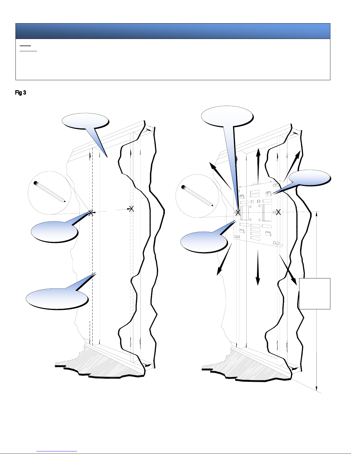
A secured structure wooden stud wall must always support the weight or load of the plasma. Always confirm the center of the wood
stud before beginning the installation.
Do not install in locations where there is vibration, movement or danger of impact. Failure to do so could result in plasma cracking or
falling from the wall causing damage and injury.
Do not install near heater, fireplace, direct sunlight or air conditioning or any other source of direct heat energy. Failure to do so may
result in damage to the plasma television and could cause a risk of fire.
At least two qualified people should always perform the installation work. Injury and damage can result from dropping or mishandling
the plasma television.
Mounting structure recommended wood studs, solid-flat concrete, and reinforced metal studs. If installing the mount on other than
wood studs use (commercially available) suitable hardware.

- 4 -
16.000
5.460
1.250
3.250
16.000
4.500
1.750
18.500
1.125
8.000
8.000
5.000
1.000
4.500
5.460
2.865
3.500
e
c
A
b
19.771
F
d
TILT BACK PLATE
MOUNTING BRACKET
PART#:
PSB-TBP
MATERIAL:
12 (GA) CRS
COLOR:
Black powder coat
A.
Lag bolt access slot.
B.
Mounting points (4.5") used on
installations other than wall mounting.
C.
Access hole for power or cables.
D.
Mounting points for additional security
screws.
PART#:
Mounting bracket
MATERIAL:
12 (GA) P & O
COLOR:
Black Powder coat
Mount Diagrams

- 5 -
oPhillips screwdriver
oDrill gun
oSoft material or a blanket
oPencil
o¼" drill bit
oLevel
oMeasuring tape
oWrench with a 1/2" socket
oStud finder
QTY SIZE DESCRIPTION
6 5/16” Dia Lag bolts
1 Mounting bracket
1 PSB-TBP tilt back plate
2 M6 x 12 (mm) Phillip security
screws Used for additional security on
tilt mounts, mobile carts, floor
stands and ceiling mounts
1 Installations instructions
6 M8 x 20 Phillip screws Mount hardware
Parts List
TOOLS NEEDED
HARDWARE LIST
PSA-1
Height adjustable
ceiling adapter
PCA-1
Ceilin
g
ada
p
ter

- 6 -
Step 1
CAUTION: The plasma displays are fragile and heavy. At least two (2) qualified personnel are strongly recommended for the installation of this product.
Invert the plasma display and set it on a flat and soft material such as (blankets, foam, cloth etc.) to prevent any damage to the plasma display. See fig 1.
WARNING : Proper installation procedure by qualified personnel as outlined in the installation instructions must be adhered to. Failure to do so could
result in serious personal injury and possible damage to the plasma display.
Step 2
Locate the mounting points found on the back of the plasma display, align the mounting holes from the mounting bracket to the holes on the plasma display. Arrow
found on the mount must always be pointing to the top of the plasma display before securing it to the plasma display. Loosely install the six (6) M8 x 20 Phillip
screws to the plasma then secure the screws with a Phillips screwdriver CAUTION: Do not over tighten the M8 x 20 Phillips screws. See fig 2.
WARNING: Do not use a drill gun to secure the screws to the plasma display. A Phillips head screwdriver is preferred.
Installing the mounting bracket
Soft and flat surface
blankets, foam, cloth
etc.
Inverted plasma
dis
p
la
y
Top of the plasma
dis
p
la
y
Bottom of the
p
lasma dis
p
la
y
Inverted plasma
dis
p
la
y
Mounting bracket
Mounting hardware
(6) M8 x 10 Phillip
screws

- 7 -
floor floor
16"
Wall structure
Wood studs behind
the wall structure
Stud centers
marking
Tilt back plate
A
djusting the
mount
Desired height
marking
Installing the mounts
CENTER
OF
VIEWING
HEIGHT
Step 3
CAUTION: The plasma displays are fragile and heavy.At least two (2) qualified personnel are strongly recommended for the installation of this product.
Please verify that your plasma mounting points from the back of the chassis are centered before installing the back plate if not take proper measurements for your installation
requirements. Select the area where the plasma will be installed and make sure it can support the weight standards (see warning on page 3). Locate the 16" wood stud centers behind
the wall using a (commercially available) stud finder and mark the center of the studs when found. Setthe mounting bracket to the wall and mark the desired height by marking the wall
mount. See fig 3.

- 8 -
floor floor
Once the height is determined, use the bubble level to insure that the bracket is level. Next, using a pencil, mark the six (6) lag bolt slot openings on the mounting bracket. Before
continuing, confirm the marks are located on the center of the studs. Drill 1/4" pilot holes on the six (6) markings on the wall. Raise the tilt back plate and have someone hold it in place
(arrow side away from the wall and pointing up). Put the lag bolt through the flat washers. Screw the lag bolt through the upper left slot opening into the 1/4" pilot hole. Confirm that
the wall mount is still leveled and then screw a lag bolt to the upper right side slot opening into the 1/4" pilot hole. Then install the remaining four lag bolts tightly into the wall studs in
the lower left and right slot openings on the wall mount.
Make any lateral positioning if any then secure the lag bolts. See fig 4.
Wood studs behind
the wall structure
Drill gun with a 1/4"
drill bit
Wall structure
Marking on wall
Flat washers
5/16" Lag bolts
Access holes
Tilt back plate
Electrical
Step 4
All electrical wiring components should be installed at this time to ensure that the plasma display has enough power sources.
Note: Pre drill before the securing the
5/16" la
g
bolts.
Caution: Do not over tighten the 5/16" lag bolts
Center of
viewing marks

- 9 -
Securing the mount
Step 5
Warning: The plasma display is heavy and 2 people are needed to lift and install it. Failure to do so could result in serious personal injury.
Before placing the plasma on the wall recheck all hardware for proper tightness and security. Before installing, become familiar with the way the plasma mount attaches to the wall
mount. Align the four (4) tab openings to the four (4) receiving tabs on the tilt back plate. When all four (4) the tabs are aligned slide the plasma down, right and down again to lock the
mounts together. Make sure all (4) tab openings are interlocked with the receiving tabs before letting go of the plasma.See fig 5.
Plasma display
Mounting
bracket
Tilt back plate
(4) Tab
openings
Wall structure
Plasma display
Wall structure
A
lign all four (4) tab
openings to the tilt
back plate receiving
tabs and push the
plasma as shown on
arrows to lock in place
Caution: The plasma display is heavy and 2 people are needed to lift and
install it. Failure to do so could result in serious personal injury.
Caution: All four (4) receiving tab openings from the
mounting bracket must be locked to the tabs found on
the tilt back plate before letting go of the plasma
display. See the diagram on the left to see the
interlocked tab.
Locked tab
Additional security
Step 6
For additional security gradually tilt the bracket forward using a Phillips screwdriver. Secure the two (2) M6 x 12 (mm) Phillips screws (screws) see fig 6. Do notover tighten the screws.
Position the bracket to the desired angle. See fig 6.
(4) Securing
tabs
Other manuals for PWM-6121
1
Table of contents
Other Pioneer TV Mount manuals

Pioneer
Pioneer KRP-TS01 User manual

Pioneer
Pioneer PDK-TS30 User manual

Pioneer
Pioneer PDK-WT02 User manual

Pioneer
Pioneer PWM-6121 Guide

Pioneer
Pioneer 12.301321-06 User manual

Pioneer
Pioneer PDK-TS25 User manual

Pioneer
Pioneer PDK-5011 User manual

Pioneer
Pioneer PWM-F110 - Bracket For Plasma Panel User manual

Pioneer
Pioneer PWM-6111 User manual