PIPE LIGHTING pipe junior 2 Assembly instructions

USER’S
MANUAL
GUIDE
pipe junior 2
pipe junior 4
pipe junior 6
pipe junior 8

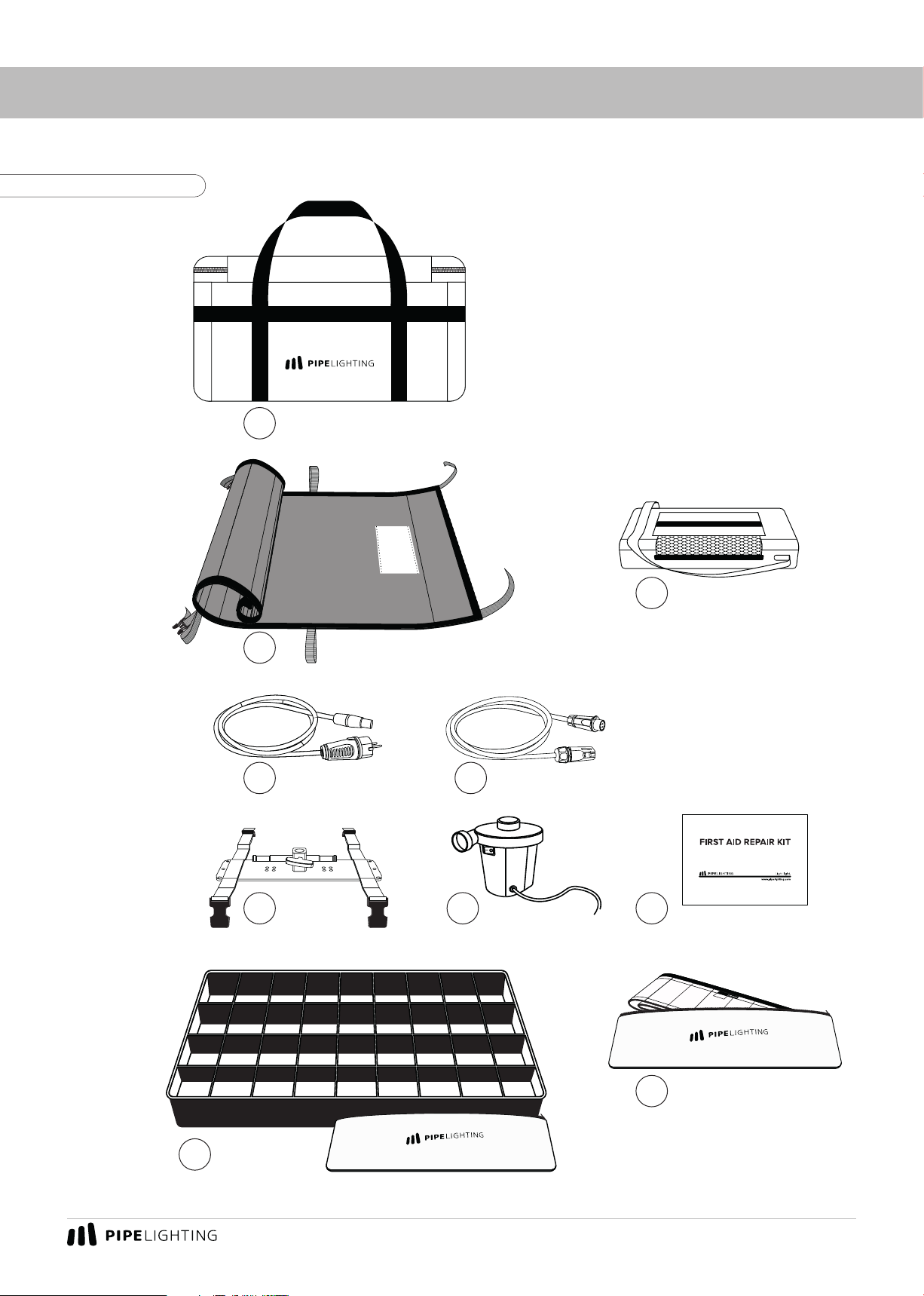
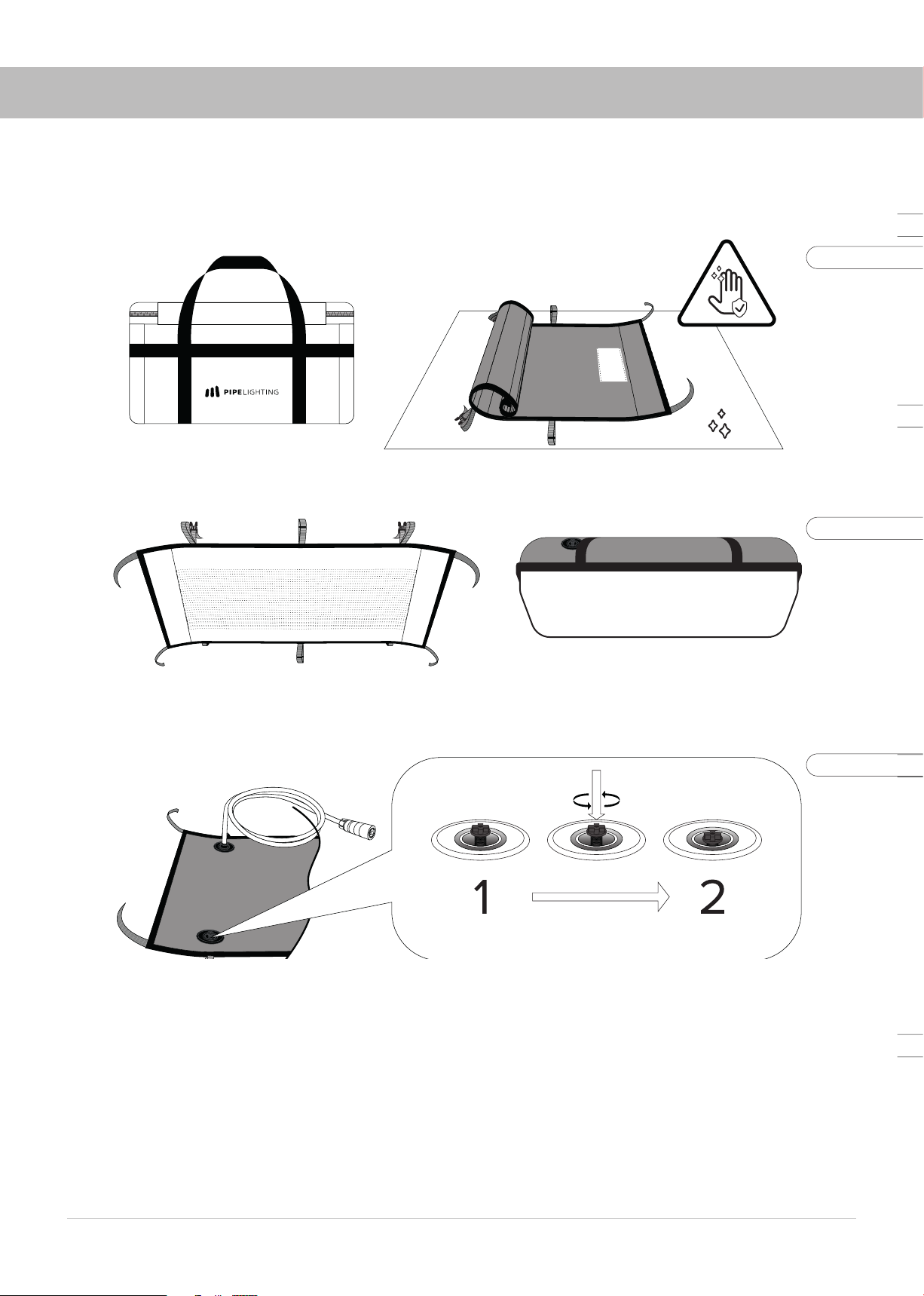
Product package..........................................................................................................................................................................................................
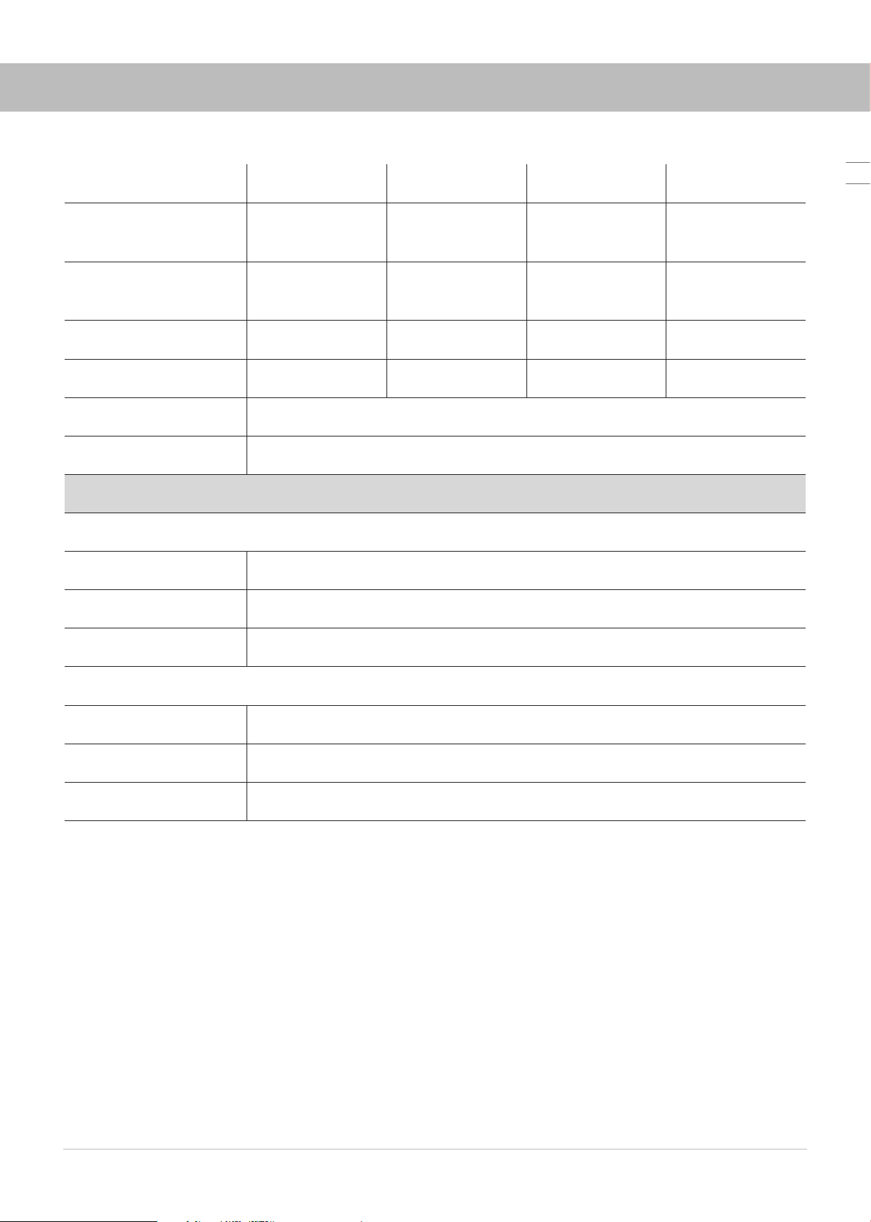
Technical specifications.............................................................................................................................................................................................
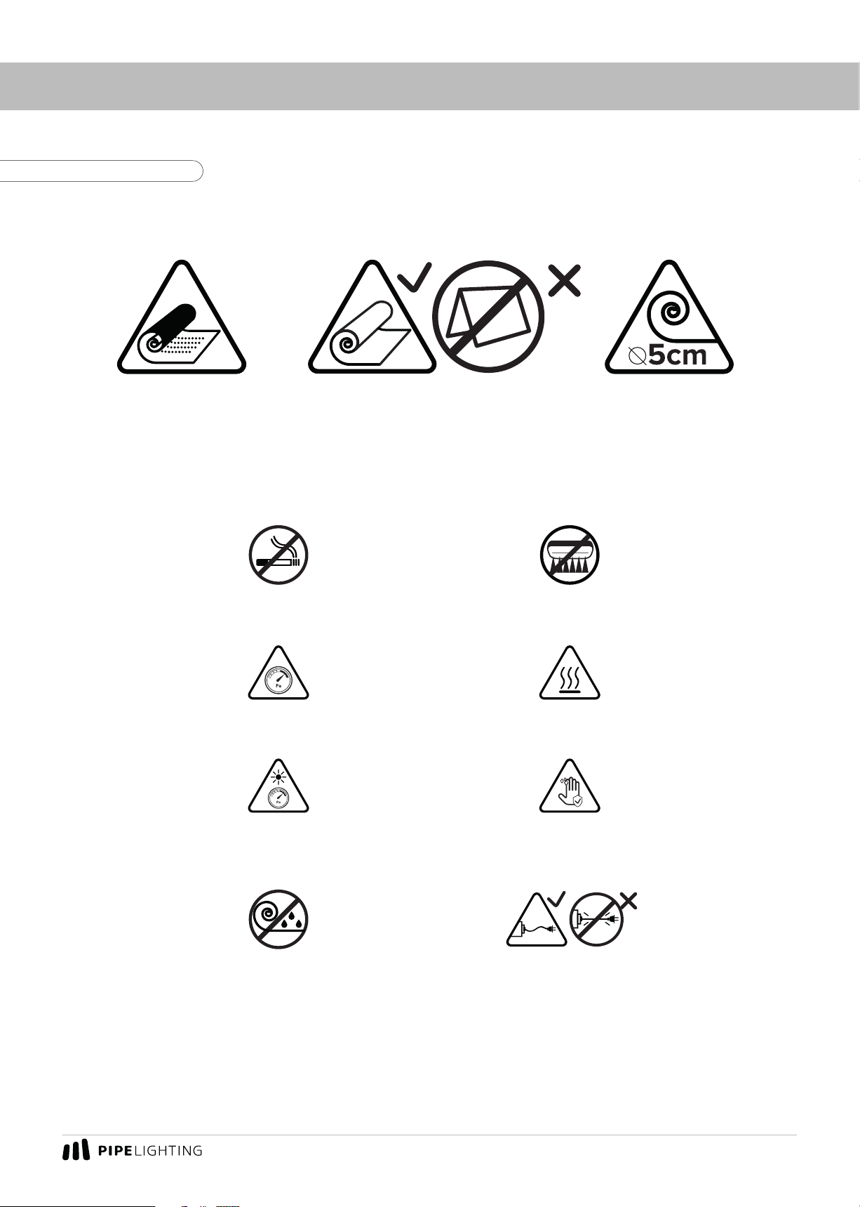
Usage precautions.......................................................................................................................................................................................................
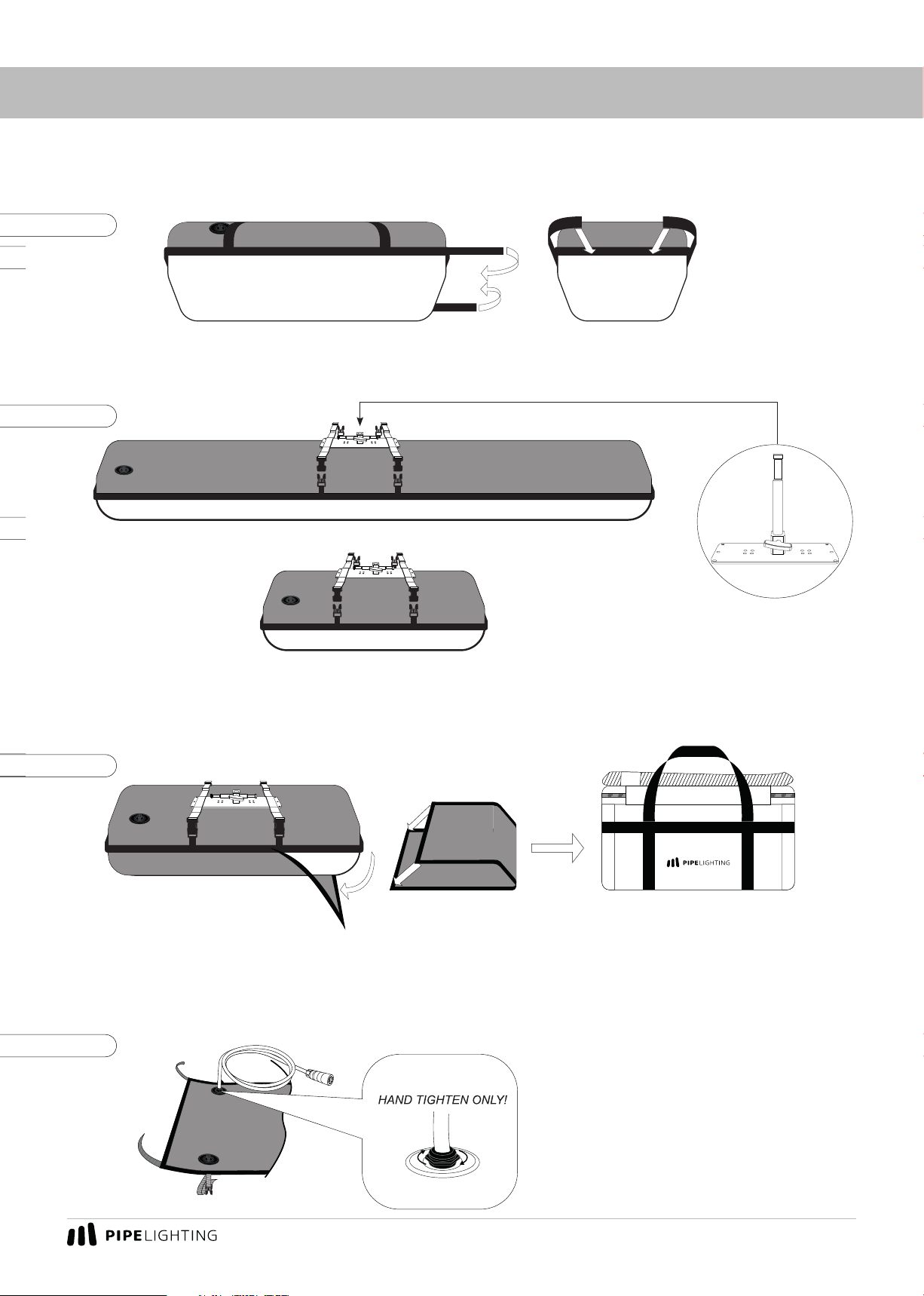
Getting ready for operation......................................................................................................................................................................................
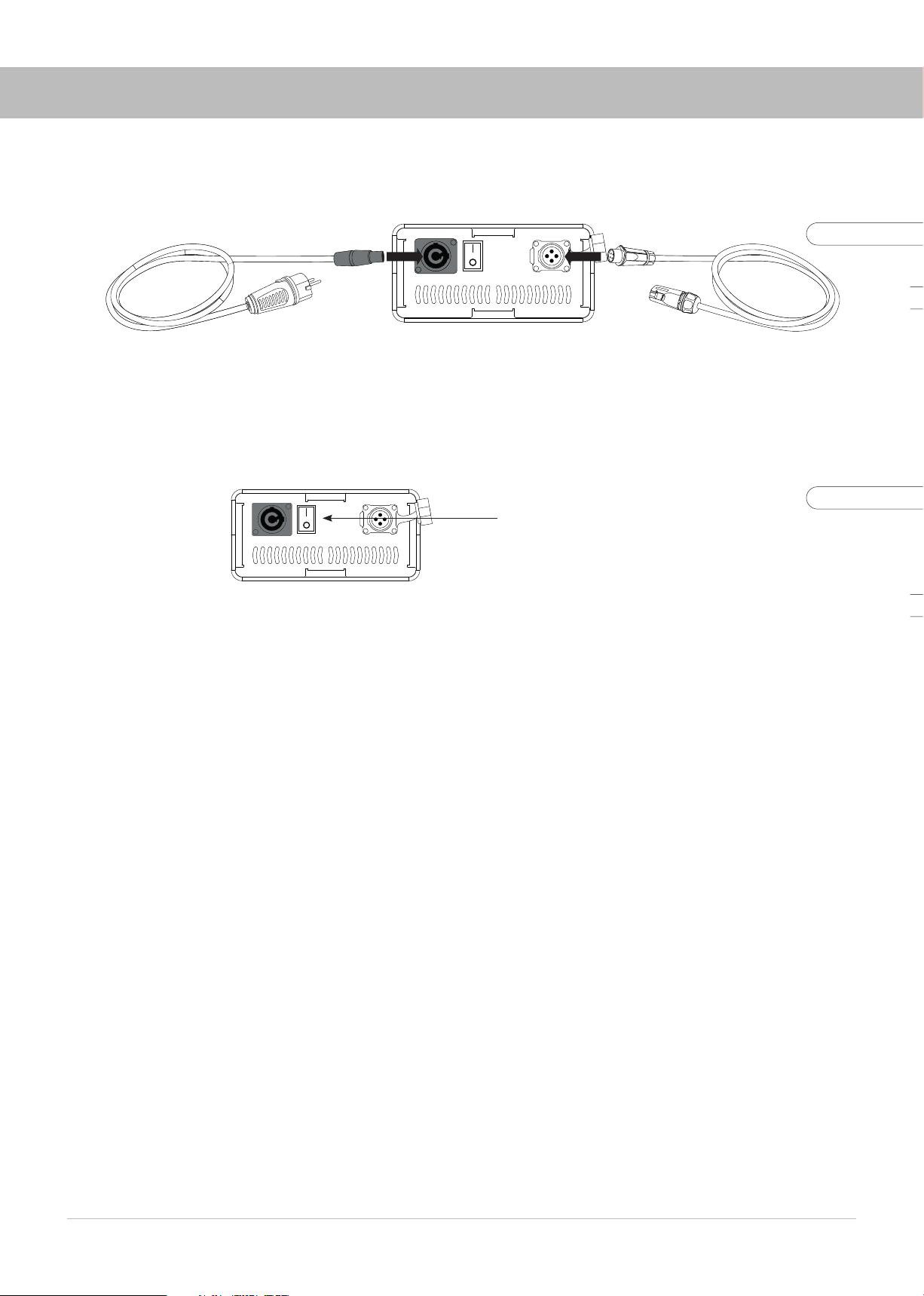
Connecting the controller..........................................................................................................................................................................................
Controller protective cover ......................................................................................................................................................................................
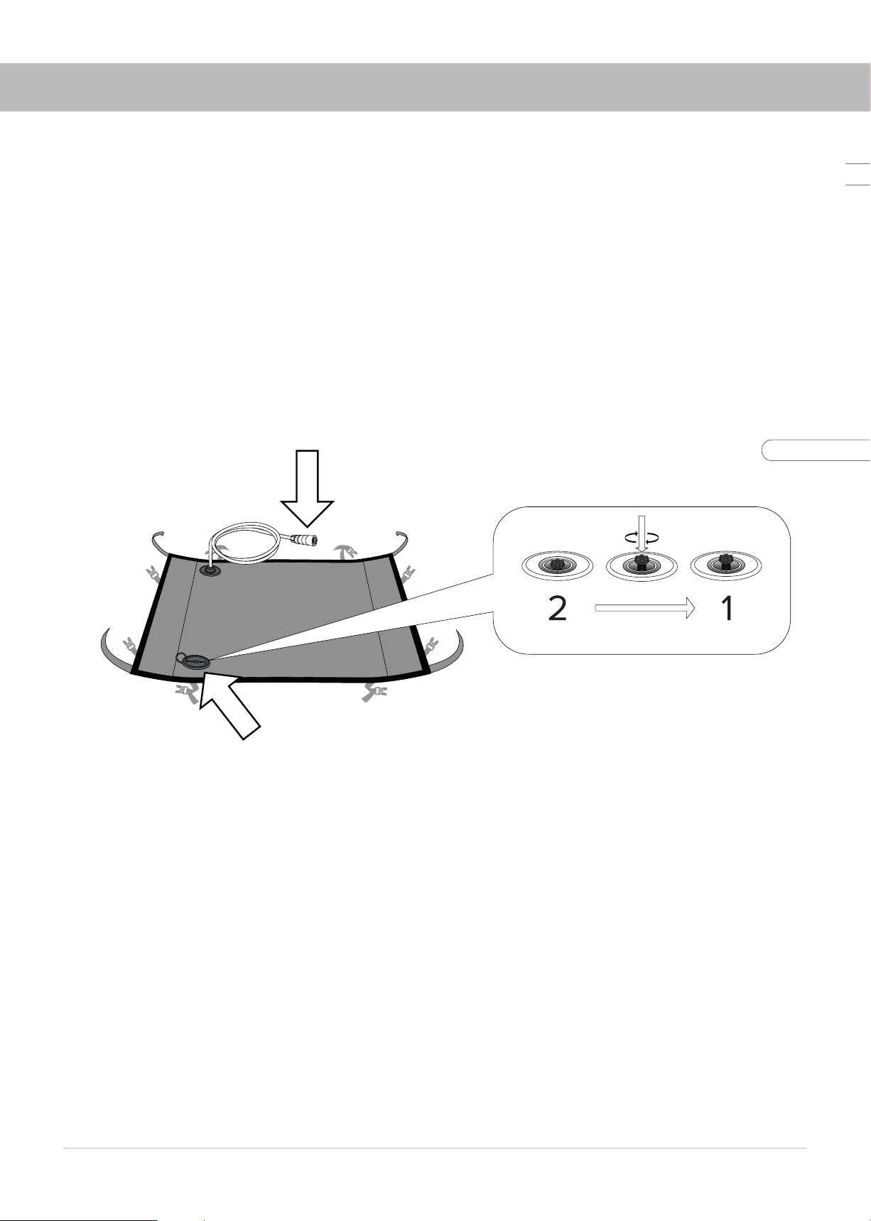
Underwater usage.......................................................................................................................................................................................................
Controller settings......................................................................................................................................................................................................
DMX Menu......................................................................................................................................................................................................
User Menu.....................................................................................................................................................................................................
User Menu: Separate Mode.....................................................................................................................................................................
User Menu: DMX_seq................................................................................................................................................................................
User Menu: Overdrive mode...................................................................................................................................................................
User Menu: Max. Power............................................................................................................................................................................
User Menu: Step Change Ratio..............................................................................................................................................................
User Menu: Smooth Transition..............................................................................................................................................................
User Menu: Reset.......................................................................................................................................................................................
Resetting CRMX network adapter........................................................................................................................................................
Finishing work and packing order........................................................................................................................................................................
Warranty........................................................................................................................................................................................................................
CONTENTS
2
3
4
5
7
8
9
10
12
13
14
16
17
19
20
21
22
23
24
25

3
PRODUCT PACKAGE
1
2
3
4 5
6 7 8
10
9
1. Transportation bag
2. Lamp Head – “Pipe”
3. Controller in bag
4. AC-Cable
5. Extension cable (5m)
6. Mounting pad with straps
7. Air pump
8. Repair Kit
9. Eggcrate (Soft grid) in bag
10. Skirt in bag
Fig. 1. Product package

User's Manual
4
TECHNICAL SPECIFICATIONS
Model PIPE JUNIOR 2 PIPE JUNIOR 4PIPE JUNIOR 6PIPE JUNIOR 8
Lamp head size
(L × W × H), cm 602020 1202020 180x20x20 240x20x20
Lamp head weight,
kg 0,9 1,4 1,8 2,1
Voltage, V 24 24 24 24
Total power rating, W 100 200 300- 400
CRI 95+
CCT 2650 K – 5700 K
Operation Conditions
Controller
Operating T, 0C Min: -15C / Max: +40C
Storage T, 0C 15-20C
IP Rating IP20
Lamp Head
Operating T, 0C Min: -15C / Max: +40C
Storage T, 0C 15-20C
IP Rating IP67

5
USAGE PRECAUTIONS
DO NOT SMOKE
DURING OPERATION!
AVOID SHARP OBJECTS!
DO NOT FOLD OR
STORE WET EQUIPMENT
AVOID OVERINFLATING!
LAMP HEAD GETS HOT!
DO NOT USE THE FIXTURES
NEAR HOT SURFACES OR OBJECTS
USING THE FIXTURE UNDER DIRECT SUNLIGHT
OR HIGH TEMPERATURES MORE THAN 30
CHECK THE PRESSURE!
DO NOT TOUCH THE LAMP HEAD
WITH DIRTY HANDS!
DO NOT WEAR GLOVES!
AVOID TENSION
ON POWER AND CONTROL CABLES!
ROLL THE LAMP HEAD
WITH THE MINIMAL
INNER DIAMETER 5CM
DO NOT FOLD THE LAMP HEAD!ROLL WITH
THE LEDS INWARDS
ONLY!
Fig. 2. Usage precautions

User's Manual
6
1. Open the case, take the lamp head with clean hands. Unroll the lamp head on a flat clean surface
without any sharp or hot objects (Fig. 3).
2. The device can be used both inflated and deflated (Fig. 4).
3. Open the air valve cover and make sure that the air valve button is in position 2. The positions of
the air valve button 1 and 2are shown in Fig. 5.
4. Inflate the lamp head with the air pump provided by bringing the pump to the valve. Make sure the
lamp head had reached its shape. Do not overinflate! Move the pump away from the valve and quickly
move the valve button to position 1. If necessary, inflate the lamp head slightly through the closed valve
by pushing the pump on the valve button. To release pressure push the valve.
GETTING READY FOR OPERATION
Fig. 3
Fig. 4
Fig. 5

7
mounting on tripod
5. Fold the corners of the lamp head with Velcro to the end face, fasten with Velcro as shown in Fig.6.
6. Attach the mounting pad to the lamp head (Fig.7). Adjust the fastening straps on the rear side of
the device.
7. Fix the instrument in operating position on the tripod.
8. Remove the protective cover from the lamp head head. Carefully fold the protective cover with
the clean side inwards and put it into the bag (Fig.8).
9. If necessary, attach a soft grid/eggcrate and/or skirt (included) to the instrument head.
10. Check the tightness of the nut of the cable valve on the lamp head from time to time.
Tighten with handpower only! Do not use wrench! (Fig.9)
GETTING READY FOR OPERATION
clean side
Fig. 6
Fig. 7
Fig. 8
Fig. 9

User's Manual
8
CONNECTING THE CONTROLLER
1. Align the connectors of the signal cable and the controller as shown in Fig.10.
2. Connect the power AC-cable to the connector on the body and the 220V socket.
3. Switch on the controller (Fig.11).
AC-Cable Extension cable
ON toggle switch
Fig. 10
Fig. 11

9
CONTROLLER PROTECTIVE COVER
The controller protective cover has two operating positions. Position 1(Fig. 12) with air vent open
is the main operating position. When used outdoors during rainfall, the flaps of the cover should be
folded to position 2 (Fig. 12).
Fig. 12
Fig. 13
It is also possible to use the flaps of the flap to form a mounting bracket with which the controller
can be mounted on a tripod (Fig. 13).

User's Manual
10
UNDERWATER USAGE
You can use Pipe Lighting products under water. To do so please take all the air out of the fixture
with the back side of the air pump. Make sure to fix the lamp head properly under water using weights
and/or frame.
Maximum guaranteed water depth: 2m.
ATTENTION: Make sure to close the air valve (put it in 1position) and the cap of the valve on the
lamp head! Danger of moisture entering the lamp head! The cable connector must stay above the
water surface! (Fig.14)
The valve is not airtight, it reduces, but does not eliminate the possibility of moisture entering
the device!
Fig. 14.
KEEP IT DRY!
PUT THE AIR VALVE IN 1POSITION AND CLOSE THE CAP!

11
CONTROLLER
General view
Front panel Rear panel
1
2
3
4 5 6
7
8
9 10 11
1. CRMX antenna
2. Radio Level Indicator
3. OLED Display
4. Link Button
5. Color Encoder
6. Power Encoder
7. DMX Input
8. DMX Output
9. Power Input
10. Power Switch
11. LED Output
Fig. 15. Controller

User's Manual
12
1. After switching the unit on, you will see the main screen (Fig.16).
2. The left encoder controls the color temperature. The right encoder controls the brightness of the
unit (Fig. 17).
3. Pressing the right encoder shows the internal temperature of the controller (Fig. 18).
CONTROLLER SETTINGS
Fig. 16
Fig. 17
Fig. 18

13
The DMX address must be set to control the unit remotely. The address has the same value for both
wired and wireless DMX. Pipe Lighting controller uses 2 DMX-channels (except in Separate Mode):
one for the color temperature and one for the brightness.
1. Pressing the left encoder brings up a menu to enable DMX control and set the devices DMX
address (Fig.19).
2. Rotating the left encoder toggles to the parameter edit mode (Fig.20).
3. Pressing the left encoder will switch to the DMX address editing mode. The address can be set
in the range from 1 to 510. Confirmation of the selection is made by pressing the left encoder again.
The RL parameter enables/disables the radio control of the unit.
The DMX parameter enables/disables the wired DMX control of the unit.
Selecting Back returns to the main screen without changing any parameters.
Selecting Ok saves the changes made to the parameters and returns to the main screen. (Fig.21).
CONTROLLER SETUP / DMX MENU
Fig. 19
Fig. 20
Fig. 21

User's Manual
14
The User menu provides access to the parameters for dierent operation modes and features of
the controller (Fig.22).
To access the User menu:
1. Switch o the device.
2. Press and hold the left encoder button.
3. Turn on the power to the controller while holding down the left encoder button.
4. Release the left encoder button when the current firmware number is shown
on the LCD screen.
CONTROLLER SETUP / User Menu
Fig. 22

15
Separate mode is mode in which two channels act independently of each other.
1. Pressing the left encoder brings up the menu to enable/disable the Separate mode (Fig. 23).
2. Rotating the left encoder knob toggles between the menu items. Pressing confirms the selected
option (Fig.24).
3. After exiting to the User menu, select Exit to save the settings (Fig.25).
4. Now you are using the Separate mode (Fig.26).
The left encoder controls the brightness of tunsten LEDs. The right encoder controls the brightness
of daylight LEDs (Fig.27).
CONTROLLER SETUP / User Menu: Separate Mode
Fig. 23
Fig. 24
Fig. 25
Fig. 26

User's Manual
16
The upper left corner shows the actual color temperature in K (Kelvin). The temperature is calculated
automatically according to the calibration of the unit and the set tungsten to daylight LED ratio (Fig.28).
The maximum power of the two groups of diodes is not limited. Each group can be set to 100% (Fig. 29).
When controlling via DMX in Separate mode 3 addresses are activated:
- brightness of tungsten diodes,
- brightness of daylight diodes,
- common virtual CONTROLLER (see DMX_seq parameter).
CONTROLLER SETUP / User Menu: Separate Mode
Fig. 27
Fig. 28
Fig. 29

17
CONTROLLER SETUP / User Menu: DMX_seq
1. Pressing the left encoder brings up a menu for setting the channel addressing sequence (see
DMX Addressing) (Fig.30).
2. Rotating the left encoder toggles between valid parameter options (Fig. 31).
3. After exiting to the User menu select Exit to save the settings(Fig. 32).
Fig. 30
Fig. 31
Fig. 32

User's Manual
18
CONTROLLER SETUP / User Menu: Overdrive mode
1. Pressing the left encoder calls the Overdrive menu (Fig.33).
2. Rotation of the left encoder toggles between the menu options. Pressing the encoder confirms
the selected parameter (Fig.34).
3. After exiting the User menu, select Exit to save the settings (Fig. 35).
4. After restarting the device the main window will switch to the Overdrive mode. In this mode it
becomes possible to turn on both control channels at 100%, which in total makes 200% in the middle
of the color temperature range at 4175 K (Fig.36).
In Overdrive mode the maximum potential of diodes of the unit is used. Each of the control channels
can be set from 0% to 100%, reaching the required color temperature.
Fig. 33
Fig. 34
Fig. 35
Fig. 36

19
A dierent maximum luminous power can be reached for each color temperature value. If at the
extremes of the range the maximum achievable power is still 100%, then in the middle of the range it
reaches 200% (both channels operating at full power).
The graph below shows the relationship between the maximum power of the device and the width
of the color temperature control range (Fig. 37).
CONTROLLER SETUP / User Menu: Overdrive mode
Диапазон изменения цветовой температуры
в режиме Overdrive при мощности 150%
3675 К
3000K
%
50
0
100
150
200
3500 4000 4500 5000 5500
4675 К
Fig. 37
Fig. 38
Color temperature range in
Overdrive mode at 150% power
Reaching 200% maximum power is only possible in the middle of the color temperature range. To
simplify the search, the middle of the range is invertibly illuminated (Fig. 38).

User's Manual
20
CONTROLLER SETUP / User Menu: Max. Power
1. Pressing the left encoder brings up a menu for selecting the Power_max parameter value (Fig.39).
2. Turning the left encoder toggles between the menu options. Pressing confirms the selected
parameter (Fig.40).
3. After exiting to the User menu, select Exit to save the settings (Fig.41).
The main window will switch to the Power_max mode.
In Power_max mode the power is limited to the selected parameter. At the same time it is possible
to adjust the power in steps of 0,2% and 0,5%, including around the zero mark (Fig.42).
Fig. 39
Fig. 40
Fig. 41
Fig. 42
This manual suits for next models
3
Table of contents
Other PIPE LIGHTING Lighting Equipment manuals
Popular Lighting Equipment manuals by other brands

FlashPoint
FlashPoint FPLFBD quick start guide

Coemar
Coemar Stage Lite Led sc instruction manual

HIKOKI
HIKOKI UB 18DH Handling instructions

Larson Electronics
Larson Electronics HAL-RSL Series instruction manual

FRC
FRC SPECTRA MAX-S Wiring, installation and mounting templates

One Stop Gardens
One Stop Gardens 57715 Owner's manual & safety instructions