Piranha P65 User manual

IRONWORKER MODEL NUMBER P65
For Serial Numbers P65-3001 to Current Models Publication Date: May 3, 2022
Call us: 800-338-5471

Piranha Optional Tooling and Attachments
Enhance your Ironworker’s Versatility
Oversize Punch Attachments
•Expand punching capacity up to 5"
Quickset Gauging Table
•Allows you to quickly set-up your punch end
for multiple holes.
•Includes an angle gauge bar to index off the
heel of your angle and a plate gauge bar,
which indexes off the end of your plate.
•Extensions are available in left- and right-
hand styles in 5' and 10' lengths.
Backgauge
•Allows you to quickly set-up your machine to
repeat your shearing length by adding a
mechanical backstop.
•Backstop can be positioned in either the
angle, flat bar, or round bar section of the
machine.
•Available in lengths of 3', 6', 9’, or 12'.
•An electronic version is also available, which
cycles the machine automatically when
material makes contact with the backgauge
probe.
Pipe Notching Attachment
•Allows you to single notch Schedule 40 Pipe.
•A must have for handrail jobs.
•Attaches to the punch end of the machine.
•Notching dies available for 3/4", 1", 1-1/4", 1-
1/2", and 2" Schedule 40 Pipe.
Oversize Bending Attachments
•Expand your bending capacity to 24" on most
models.
•Includes a 4-way die block for different
thicknesses of material.
***Additional Options Shown on Inside of Back Cover***

Ironworker Manual
Model P65
Be sure to register your model and serial number to receive Piranha Service and
Product Updates.
Support
Please have the serial number or model ready when calling.
For technical support:
Via Phone: 815.490.0473
For ordering parts and consumables:
Via Phone: 800.338.5471
Piranha
650 Race St. • P.O. Box 1206
Rockford IL 61105, USA
www.piranhafab.com

Table of Contents 4
Table of Contents
Refer to second section of this manual for information on repair parts breakdown and
ordering repair parts.
Table of Contents....................................................................................................................... 4
Foreword.................................................................................................................................... 5
Warranty.................................................................................................................................... 5
Introduction................................................................................................................................ 6
Safety Precautions..................................................................................................................... 7
Machine Specifications .............................................................................................................. 8
Functional Diagram.................................................................................................................... 9
Dimensional Data......................................................................................................................10
Standards Compliance..............................................................................................................11
Installation.................................................................................................................................12
Operating Instructions...............................................................................................................13
Lubrication................................................................................................................................21
Maintenance.............................................................................................................................22
Troubleshooting........................................................................................................................23
Tonnage Required for Punching Holes in Mild Steel .................................................................27
Maintenance Tools List.............................................................................................................28
Ordering Repair Parts...............................................................................................................29
Service Record Chart................................................................................................................51
Piranha Optional Tooling and Attachments...............................................................................53

Piranha Ironworker P65 5
Foreword
This manual has been prepared for those persons who will operate and maintain the
Piranha Ironworker. It is important that all persons responsible for the care and operation
of this equipment read and understand the information presented in this publication.
The illustrations and instructions on the following pages were the most recent available
at the time of publication and selection of this material was made based on a standard
machine arrangement. Differences between the machine you received, and the views
contained in this manual are the result of design improvement and / or the addition of
optional accessories specified on your order.
Warranty
Piranha / MegaFab will replace (F.O.B. our factory) or refund the purchase price for any
goods which are defective in materials and workmanship within 12 months of date of
purchase. The buyer must return the warranty registration card within thirty-(30) days of
the purchase date, and at the seller's option, return the defective materials freight and
delivery prepaid to the seller, which shall be the buyer's sole remedy for defective
materials. Seller shall not be liable to purchaser or any other person for consequential or
incidental damages. Hydraulic and electrical components are subject to their respective
manufacturer's warranties. This warranty does not apply to machines and / or
components, which have been altered in any way, or subjected to abusive or abnormal
use, inadequate maintenance, and lubrication, or to use beyond seller’s recommended
capacities and specifications. Seller shall not be liable under any circumstances for labor
costs expended on such goods or consequential damages. Seller shall not be liable to
purchaser or any other person for loss or damage directly or indirectly arising from the
use of the goods, or from any other cause. No employee, agent, officer, or seller is
authorized to make oral representations or warranty of fitness or to waive any of the
foregoing terms of sale and none shall be binding on the seller.

Introduction 6
Introduction
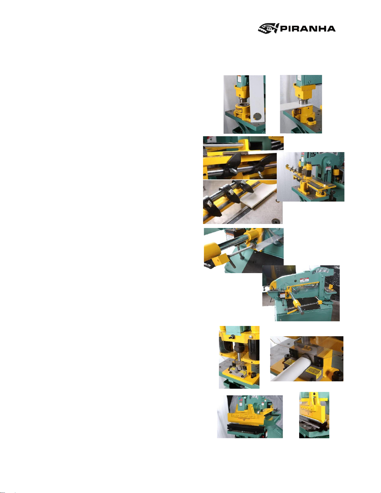
The Piranha Ironworker is a compact hydraulically powered machine that shears,
punches, bends, notches, and copes, all in a low silhouette, efficiently designed unit,
resulting in minimal floor space requirements. The integral lifting lug provides instant
portability and the unit arrives fully assembled, requiring only the addition of hydraulic oil
and electrical power to become fully operational. A quick-change mounting assembly,
utilizing a split dovetail, allows setup from punching to bending in less than one minute.
The large platen has seventeen 5/8-11 tapped holes giving a wide base for increased
flexibility of attachment sizes. The shearing operation features an adjustable automatic
hold-down allowing the operator to clamp the work piece with a slight initial adjustment.
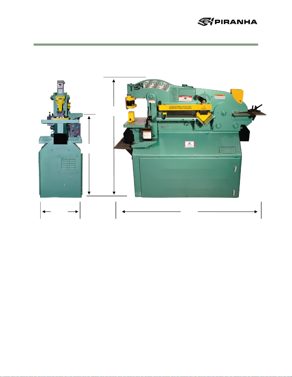
All workstations are located approximately 44" off the floor for ease of operation.
The first part of this manual provides operations and maintenance instructions, including
a section on troubleshooting various problems that may occur. The second part of this
manual provides repair parts information and a complete parts list with their respective
part numbers.
Proper understanding and application of the information and procedures given in this
manual will aid in establishing a preventative maintenance program and, provide
assistance for correcting malfunctions that may occur in the machine. The repair parts list
provides information for parts procurement as well as assembly breakdowns to aid in
disassembly and reassembly for repair part installation.
About Piranha
Piranha is a subsidiary of MegaFab, based in Rockford Illinois. MegaFab is a
manufacturer of metal fabrication machinery, including laser cutting machines, plasma
cutting machines, ironworkers, press brakes, bending rolls, combination punching and
cutting machines, and structural steel punching equipment. Equipment is sold under the
Piranha, Whitney, and Bertsch brands.

Piranha Ironworker P65 7
Safety Precautions
The operator of this machine should view the operational video provided with the
machine, and thoroughly understand this manual before starting any operation.
This machine was designed for use by a single operator only.
Wear eye protection at all times.
Use the proper voltage outlet for the machine.
Make sure that all guards and cover shields are down before starting machine.
CAUTION: Do not remove guards.
Keep hands off working tables and out of the path of moving parts during operation.
Remove all material from the tables except for the work piece.
Remove all tooling from the punch end before starting shearing or coping operations.
Make sure that all tooling is properly held in position before starting any operation.
The area around the machine should be well lit, dry, and free from obstructions.
All maintenance and repair work should be performed by a person familiar with this
publication.
At the end of the working day, power off the machine.
Adjust limit switches when punching or bending to allow 1/4" maximum clearance
between bottom of the stripper foot or bending punch and the top of the material. Contact
the factory for limit switch adjustments on special tooling.
Turn selector switch to the "OFF" position when changing tooling or performing
maintenance work. Reference Page Error! Bookmark not defined., Figure “B”).

Machine Specifications 8
Machine Specifications
HYDRAULIC SYSTEM
Drive Motor
7.5HP 230 / 460 Volt / 3 Phase
Hydraulic Tank Capacity
18 Gallons
Hydraulic Tank - Initial Fill
13.5 Gallons
Hydraulic Oil
AW-32 or Equivalent (ISO Grade 32)
Consult your local distributor for a cross reference
WORKING SURFACE
Platen Table
10" x 17"
Coper Table
15" x 15"
CAPACITIES
Punch
Maximum 1-1/16" Thru 3/4" thick material or 65 Tons
Bending
Maximum 65 Tons
Punch End
Maximum 65 Tons
Bar
1-1/2" Round or 1" Square
Plate
1" x 4" w / Fixed Hold-down, 3/4" x 10", or 5/8" x 15"
Angle
5" x 5" x 3/8" or 4" x 4” x 1/2" with Optional Knife
Coper-Notcher
2-3/4" x 4" x 1/4"
WEIGHT
Shipping Weight
2,600 Pounds

Piranha Ironworker P65 9
Functional Diagram
Rear Control Box
(OFF SIDE)
Foot Switch
Angle Table
Coper Guard
Coper Guides
COPER END
Coper Table
Shear Table
Hold-down
Stroke Control
Punch
Attachment
PUNCH END
Platen Table
Chip Bucket
Front Control
Box
Chip Bucket
Fixed Hold-down
Must be used
when shearing
1" x 4" plate
Serial Number
Plate Location
Lifting Lug

Dimensional Data 10
Dimensional Data
24"
66"
42"
60"

Piranha Ironworker P65 11
Standards Compliance
Electrical System Design/Manufacture:
The machines manufactured in Rockford, Illinois, USA are furnished with electrical /
electronic products that are UL (Underwriter's Laboratory) approved. These components
have the UL numbers printed or stamped on them and can be easily traced to the point
of manufacture. In addition, all of the machines meet the current "Ontario Hydro" electrical
code for proper manufacture of the electrical circuits.
Hydraulic System Design/Manufacture:
Hydraulic components used in Piranha machines are approved by NFPA (National Fluid
Power Association), and those approval numbers can be traced through the
manufacturer's part numbers.
ANSI/OSHA Compliance:
Piranha meets the current ANSI construction standards for manufacturing of ironworkers,
press brakes, and shears:
ANSI Bll.5 - Ironworkers, Construction, Care, and Use
ANSI Bll.3 - Power press brakes, Construction, Care, and Use
ANSI Bll.4 - Shears, Construction, Care, and Use
The ANSI B11 standards were developed to establish levels of responsibility for
manufacturing safe products, and for installing, training, and using these products. The
levels of responsibility are fairly evenly distributed between the manufacturer, the
owner/end-user of the equipment, and the operator. Specific guarding requirements are,
in general, assigned to the owner/end-user of the equipment.
With specific reference to Ironworkers, OSHA (Occupational Safety and Health
Administration) made a ruling on March 4, 1991 - under their standard number 1910.212,
specific to the OSHA Machine Guarding Standard 29 CFR 1910.212(a)(1). This ruling is
stated verbatim below:
"If an employer provides an iron worker machine (at his or her workplace),
which is manufactured in compliance with the safety requirements specified
in ANSI B 11.5-1988, and the guarding is maintained as required; then that
employer meets OSHA's machine guarding requirements for that machine."
Please understand that this ruling places the primary burden of responsibility for
maintenance of guarding on the owner/end-user of the equipment. Inherent in this
requirement is the responsibility of the owners/end-users of the equipment to develop and
maintain guarding specific to their application for the equipment. These ANSI safety
requirements may be acquired from:
American National Standard Institute
1430 Broadway
New York, New York 10018
Telephone (212) 354-3300
https://www.ansi.org/

Installation 12
Installation
Location
For the best overall performance, install the Piranha in a location that is clean and well
lighted. Provide sufficient space in all directions to allow for the material lengths of the
work pieces to be processed by the Piranha.
Foundation
To maintain the accurate alignment built into the Piranha, and to prevent undue stress on
the moving parts under a load, the Piranha should be placed on a stable base or floor
adequately constructed to withstand the unit weight. NOTE: Use the leveling bolts
provided with the machine.
Wiring
The Piranha is shipped totally wired through the electrical enclosure box. It has been left
to the owner's discretion whether to wire direct to an electrical disconnect, or to install a
cord and plug for mobility of the Piranha.
CAUTION: Compare machine wiring to input voltage prior to connecting power.
Only connect the specified voltage to the machine.
Lifting
The lifting lug on the Piranha is an integral part of the machine. Use a device with
adequate lifting capacity to handle the Piranha.
CAUTION: The unit is exceptionally top heavy! Lifting from the underside of the
machine may cause damage to the cabinet structure.
Assembly
The Piranha is pre-assembled at the factory. The only requirements are the addition of
hydraulic oil and electrical power.

Piranha Ironworker P65 13
Operating Instructions
The Piranha Ironworker comes pre-assembled and pre-wired, requiring only the addition
of hydraulic fluid in the reservoir to the mark on the fill cap dipstick and a power source
from a disconnect to the electrical enclosure box located inside the cabinet.
The unit can be started and stopped by the push button operators located on the front
cover of the control boxes on each end of the unit. See figure A below. For the Control
Box locations, reference the next page, figure E.
The electrical controls have a selector switch to determine which control box controls the
unit. This safety feature is located on the rear cover of the front control box only. See
figure B. The legend plate on the selector switch is printed "Front-Off-Rear". "Front" allows
electrical control to the Front Box only. "Off" disconnects electrical control to both control
boxes. "Rear" allows electrical control to the Rear Box only. The selector switch should
be in the "OFF" position when the machine is not being used, such as, changing tooling,
maintenance work, etc. The machine can only be started from the control box selected
via the selector switch. It can be stopped using either “stop” button.
Start
Button
Stop
Button
Four Pole
Receptacle
for Foot
Pedal
Toggle
Switch
Selector Switch
Front –Off - Rear
NOTE: Turn selector
switch to OFF
position when
performing
maintenance or
changing tooling.
Rear Cover
Front Control
Box Only
FIGURE B
FIGURE A
Front Cover
Front and Rear
Control Boxes

Operating Instructions 14
Joystick Operation
The ironworker is hand controlled by a five-position momentary joystick operator. When
the joystick is released from any of the four positions, it will return to the neutral (center)
position stopping machine movement instantly. The joysticks are located on top of the
control box at each end of the machine. See figure E below.
The four controlling positions of the joystick are:
1. Fast Down (pulling the handle forward).
2. Fast Up (pushing the handle away).
3. Jog Down (pushing the handle to the right).
4. Jog Up (pushing the handle to the left). See figures C and D.
All directions in figures C and D are determined by standing at either end and facing the
machine. The jog speed in both positions is a slow speed for alignment of center punch
marks and scribe lines for shearing. The fast cycle should be used for the work cycle.
Jog Down
FIGURE E
Control Box Locations
FIGURE D
Rear Control Box
Jog Down
Fast Up
Fast Down
Joystick Operator
Jog Up
Up Stroke
Limit Switch
Down Stroke
Limit Switch
Punch End
Note: Joystick Center
Position is Neutral
FIGURE C
Front Control Box
Fast Up
Jog Up
Joystick Operator
Fast Down
Coper End
MACHINE

Piranha Ironworker P65 15
Footswitch Operation
The ironworker can also be controlled by a footswitch. See figure below. The footswitch
is used by plugging the 4-pole twist lock cap into the 4-pole twist lock receptacle located
in the front coverof either control box (reference figure A), and switching the toggle switch
(reference figure A) from the "OFF" position to the "ON" position.
The footswitch is a three-(3) position switch allowing hands-free operation.
▪By fully depressing the footswitch lever, machine movement is downward to limit
setting (F2).
▪By allowing the footswitch lever to elevate to the center position, machine movement
stops (F3).
▪Completion of downward cycle is accomplished by depressing footswitch lever again.
Machine movement is down until limit setting is met (reference Figure F4).
▪Removing foot pressure from the switch entirely allows machine movement upward to
limit setting, completing upstroke cycle (reference Figure F5).
F1
Foot Switch
Foot Switch Lever Positions
1) Beam Moves Up
2) Beam is Stopped
3) Beam Moves Down
Foot switch lever full up
position beam elevates
to limit setting
Foot switch lever depressed
past center beam moves
down to limit setting
Foot switch lever
neutral position beam
travel is halted
Foot switch lever
depressed past center
beam moves down to limit
setting
Foot switch lever full up
position beam elevates to
limit setting
Foot Switch
Foot Switch
Foot Switch
Foot Switch
Foot Switch
F
F2
F3
F4
F5

Operating Instructions 16
Footswitch Limit Switches
The footswitch is used in conjunction with the upstroke and downstroke limit switches
located on the machine side off the front control box only, see figure C.
▪The front limit switch (closest to the punch end and the lower switch of the two
switches) controls the downstroke limit.
▪The back switch (furthest from the punch end and the higher of the two switches)
controls the upstroke limit.
▪The limit switches are activated by the limit switch arms: Item number 60, shown on
page number 31.
To set the stroke using the limit switch arms, use the following procedure:
1. Plug in footswitch.
2. Turn toggle switch to "ON" position.
3. Loosen thumbscrew on down stroke limit-switch arm.
4. Fully depress footswitch lever allowing beam to move downward.
5. Slide limit switch arm until contact with the down stroke switch stops beam movement
at the desired lower limit.
6. Tighten thumbscrew to hold limit switch arm firmly in place.
7. Loosen thumbscrew on upstroke limit-switch arm.
8. Allow footswitch lever to elevate allowing beam to rise.
9. Slide limit switch arm until contact with the upstroke switch stops beam movement at
the desired upper limit.
10.Tighten thumbscrew to hold limit switch arm firmly in place.
NOTE: When punching or using the bending attachment, set upper and lower limits to
allow for 1/4" maximum clearance between the bottom of the punch and the top of the
work material. The setting will change when the work material thickness changes.
NOTE: The downstroke limit switch on the punch end controls the upstroke limit on the
coper end. The upstroke limit is the only switch controlled from the rear control box
footswitch control. The operator controls the downstroke limit by allowing the footswitch
lever to fully elevate after the upper coper knife passes through the material.

Piranha Ironworker P65 17
Punch/Stripper Attachment Alignment
The alignment of the punch and die should be accomplished in the following manner.
(Reference page 31 and page 37).
1. Slide the punch stripper assembly on the dovetail-mounting shoe.
2. Tighten the locking shoe by turning the cap screw clockwise (requires 3/8” Allen
wrench). This locks the stripper assembly firmly in place.
3. Remove the coupling nut from the punch stem using the coupling wrench.
4. Insert the punch in the coupling nut and tighten on the punch stem using the
coupling wrench.
5. Insert the female die in the die block.
6. Tighten the setscrew against the female die (requires 3/16” Allen wrench).
7. Slide the die block around the setscrews on the platen table. Do not tighten the
flanged nuts.
8. Switch the front control box toggle switch (reference Figure "A") to the “OFF”
position. Disconnect the foot switch from the receptacle.
9. Start the machine. Use the front control box joystick in the jog down mode
(reference Figure "C"), to move the beam downward. Stop beam movement
when the bottom of the stripper foot is approximately 1/8" above the die block.
10.Align the punch and die visually and by hand movement of the die block. Jog
down again slightly and align. Continue this procedure until the punch has
passed through into the die.
11.Using the wrench supplied with the machine, tighten the flanged nuts on the
setscrews to hold the die block firmly to the platen table.
12.Set the limit switches to control the length of stroke. Reference previous page.
13.Start operation.
14.Remove all tooling from the punch end before starting shearing or coping
operations.

Operating Instructions 18
Stripper Assembly Adjustment
NOTE: The selector switch should be in the "OFF" position until all tooling changes are
complete. Reference page 13, figure B.
The adjustment of the stripper assembly to compensate for varying punch lengths should
be accomplished in the following manner. (Reference page 37 for a visual reference).
NOTE: The correct adjustment should have the tip of the punch 1/16”below the bottom
of the stripper footplate and the stripper footplate level.
1. Install the stripper assembly on the upper beam (reference instructions
previously listed).
2. Insert punch in the stripper assembly (reference instructions previously listed).
3. Measure the length of the punch relative to the bottom of the stripper foot.
4. If the tip of the punch extends more than 1/16" below the bottom of the stripper
foot, adjustment is required.
5. Turn the two (2) guide pin adjusting caps counterclockwise until the tip of the
punch extends 1/16”below the bottom of the stripper footplate. The stripper
footplate MUST remain level or parallel to the work material. The punch tip
should be able to line up on a center punch mark before the stripper footplate
engages the material.
6. If the tip of the punch does not extend 1/16”below the bottom of the stripper foot,
or if the stripper footplate is not parallel with the work material, adjustment is
required.
7. Turn the two (2) guide pin adjusting caps clockwise until the tip of the punch
extends 1/16" below the bottom of the stripper footplate. The stripper footplate
MUST remain level or parallel to the work material. The punch tip should be able
to line up on a center punch mark before the stripper footplate engages the
material.

Piranha Ironworker P65 19
Bending Attachment Alignment
The alignment of the bending punch and bending die should be accomplished by the
following manner. (Reference page 31 and page 39).
1. Slide the bending punch assembly on the dovetail-mounting shoe. The front edge of
the bending dovetail slide should be even with the mounting shoe
2. Tighten the locking shoe by turning the cap screw clockwise (requires 3/8” Allen
wrench). This locks the bending punch assembly firmly in place.
3. Place the bending base holders on the platen table over the setscrews. Do not
tighten flanged nuts.
4. Place the four-way bending die into the bending base holder with the proper width
die opening on the top.
5. Switch the front control box toggle switch (Reference Figure "A") to the “OFF”
position and disconnect the foot switch from the receptacle.
6. Start the machine. Using the front control box joystick in the jog down mode
(Reference Figure "C"), move the beam downward.
7. When contact between the bending punch and the bending die block opening is
made, the bending die block will center itself.
8. Using the wrench supplied with the machine, tighten flanged nuts on the setscrews
to hold the base assembly firmly to the platen.
9. Set the limit switches to control the length of stroke (reference procedures previously
listed).
10.Start operation.

Operating Instructions 20
Shear Hold-Down Assembly Adjustment
The adjustment on the hold-down assembly should be accomplished by the following
manner. (Reference page 35).
1. Raise the upper beam to its full upstroke limit.
2. Adjust the three-position hold-down locator per the following instructions:
•Locator hole nearest punch end - Plate = 1/4" thick and less, Angle = 3/16"
thick and less.
•Locator hole center position - Plate = 5/16" to 1/2" thick, Angle = 1/4" to
5/16" thick.
•Locator hole nearest the coper end - Plate = 5/8" to 1" thick, Angle = 3/8" to
1/2" thick*
*NOTE: Shearing 1/2" thick angle requires the optional 1/2" upper angle knife not
provided with the standard machine.
3. Loosen the long hex head nut without removing it from the swing bolt, raising the
hold-down assembly.
4. Assure the hold-down bar has risen until it is directly under the long nut.
5. Insert material to be sheared under the hold-down assembly.
6. Tighten the long hex head nut to allow for approximately 1/8" clearance between
the bottom of the shear urethane and the top of the material to be sheared. The
material should move freely and not be held by the hold-down assembly at this
point.
7. Lower the beam using the front control box joystick in the jog mode (reference
Figure "C") until the hold-down assembly firmly clamps the material.
NOTE: The hold-down assembly must firmly clamp the material before the
shear knives engage the material surface.
8. If the foot switch is to be used during the operation, adjust the limit switches to
control the length of stroke (reference procedures previously listed).
NOTE: Do not attempt to shear any material that will not be held by the Hold-down
Assembly. When shearing up to 1" X 4" flat bar, install the Fixed Flat Bar
Hold-down, Part Number 0330129 to the front of the shear table. Make sure
the material is held properly at the urethane and that the material extends
into the fixed flat bar hold-down area as well. The Fixed Flat Bar Hold-down
acts as a bumper bar assisting the Urethane Hold-down in its normal
function.
Table of contents
Popular Lathe manuals by other brands

Holzstar
Holzstar DB 900 instruction manual

HOLZMANN MASCHINEN
HOLZMANN MASCHINEN ED 1080A user manual

Index
Index Traub ABC operating instructions

Central Machinery
Central Machinery 93212 Set up and operating instructions

BUILDPRO
BUILDPRO ATN100 Assembly instructions

Craftsman
Craftsman 113.228360 owner's manual