PIRATE MIDI BRIDGE6 User manual

1. Unboxing
You can watch the video version of this chapter here.
Woo! Your new MIDI controller has arrived!
In the box you should find:
1x BRIDGE6 MIDI controller (obviously)
1x 2 metre USB type A to type C cable (black)
4x Self-adhesive rubber feet
1x ‘Getting Started’ card
1x Flexiport Warning card
The box and getting started cards are completely recyclable, so please make sure to
dispose of them responsibly if you don’t keep them.
Now, let’s stop drooling and plug it in!

2. Device Layout
Your BRIDGE6 is a masterpiece of design and engineering (just ask us!). Here
is an overview of the device.
The features of each input/output are detailed in “4. Connectors”
From left to right:
●USB (type-C)
○Power
○USB MIDI In/Out
●TRS MIDI In (6.35mm / ¼” TRS)
○Dedicated MIDI Input (only)
●DIN5 MIDI Out
○Dedicated MIDI Output (only)
●9v DC (2.1mm centre-negative)
○Power
●TRS Flexiports x2 (6.35mm / ¼” TRS)

○MIDI Out
○Expression In
○Ext Switch In
○Switch Out
○Tap Tempo Output
○Sync Pulse Out
○Device Link
●Footswitches
○Six silent footswitches are the main interface on the BRIDGE6. Rated for
over 100,000 presses each, they are able to send different MIDI message
stacks for different press types (Toggle On, Toggle Off, Press, Release,
Double Press, Hold, Hold Release).
Each switch is able to send 176 MIDI messages per bank:
■Toggle On: 48
■Toggle Off: 48
■Press: 16
■Release: 16

■Hold: 16
■Hold Release: 16
■Double Press: 16
●OLED Display
○A large graphical display allows us to display symbols and icons to
make the user interface easier to use.
The beauty of an OLED is the crisp, high-contrast display. Easily readable
from a distance with no need for an annoying backlight.
By default, the OLED shows the bank name in the centre, and each
switch label is set to “FS ‘x”. Switch labels and bank names are editable
through the onboard menus and the app.
●RGB LEDs
○Each switch is paired with a curved light pipe that houses 2 independent
RGB LEDs. This means you can choose from millions of colours per
switch and combine different LED states/colours to create your own
custom interface.
Note: Changing colours is possible in the device menus, but is limited to
preset colours. For free choice, use our app.
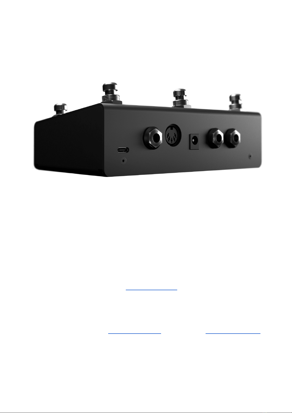
3. Power & Navigation
You can watch the video version of this chapter here.
You can power your BRIDGE6 with either a USB cable, or a centre-negative 9v DC jack
(2.1mm) commonly used for guitar pedals.
The BRIDGE6 uses smart power switching so you can have both plugged in at once,
and if you need to remove one or the other, the unit will seamlessly switch power
sources without shutting down or restarting.

If you’re using a 9v DC power supply, please make sure
it is able to supply the required 200mA.
Basic Navigation
Bank Up & Bank Down
As indicated by the arrows at the bottom of the OLED screen, pressing switches 2 & 3
at the same time will advance to the next bank (Bank Up) and pressing switches 1 &
2 at the same time will go to the previous bank (Bank Down). This is indicated by the
two arrows displayed on the screen (visible on below diagram)
There are 100 banks (0-99). Banking up from bank 99 will return you to bank 0.
Banking down from bank 0 will send you to bank 99.
Opening the Menu

To enter the menu, press and hold down switches 1 & 4 simultaneously (as pictured
below). You will know you’ve entered the menu when the screen layout changes.
Press switch 1 or switch 3 to navigate the menu (note the arrows on screen).
Press switch 2 to select or set (like an ‘enter’ or ‘return’ key on a computer).
Press switch 4 to ‘go back’ to the previous menu screen.
Hold switch 4 on any menu screen to completely exit the menu.
Second-Screen Settings
When editing parameters like MIDI message details, LFO settings etc. there may be a
second (or third) screen of settings. To access these pages, use the left and right
arrows on switch 5 & 6 to navigate across the screen.

You can see an example of a screen with left and right arrows below. The active area
(“type”) is highlighted with a box. This highlight box will move as you navigate with
switch 5 & 6.
These pages are “circular” and navigating across in one direction will eventually bring
you back to the place you started.
That’s the end of the basic navigation instructions. After this you should be able to
figure out how to navigate all the menus and settings. You can watch the video linked
at the top of this page if you’d like to cover the content again in a different format.

4.1 Overview of Connectors
From left to right:
●USB (type-C)
○The BRIDGE6 can be powered by USB, and is also a class-compliant USB
MIDI device. This means it will be recognised as a MIDI device without
any drivers. Use it with your DAW, plugins, or music apps.
●TRS MIDI In
○A ¼” (6.35mm) TRS Jack designated as a dedicated MIDI input. This
Input conforms to the MIDI Specification.
●DIN5 MIDI Out
○A DIN5 Jack designated as a dedicated MIDI output. This MIDI output
conforms to the MIDI Specification and can power CME WIDI products.
●9v DC (centre-negative)

○A 2.1mm centre-negative barrel jack (common with standard guitar
pedal power supplies). Requires 200mA.
●TRS Flexiport 2
○A ¼” (6.35mm) TRS jack with 8 modes (and counting):
■MIDI Out
(can power CME WIDI devices)
■Exp In
(Single Expression Pedal Input)
■Exp-Doubler In
(Enables two expression pedal inputs per Flexiport with our
Exp-Doubler device)
■Ext Switch
(1, 2, or 3 switches supported)
■Switch Out
(Send TRS switch emulation to non-MIDI devices with an external
control jack - Helix, Boss, etc)
■Tap Tempo Out
(MIDI Clock as switch output)
■Sync Pulse Out
(Square wave output for syncing non-MIDI devices to MIDI Clock
such as Teenage Engineering Pocket Operator series)
■Device Link
(connect multiple PIRATE MIDI devices together)
●TRS Flexiport 1
○A ¼” (6.35mm) TRS jack with 8 modes (and counting):
■MIDI Out
(can power CME WIDI devices)

■Exp In
(Single Expression Pedal Input)
■Exp-Doubler In
(Enables two expression pedal inputs per Flexiport with our
Exp-Doubler device)
■Ext Switch
(1, 2, or 3 switches supported)
■Switch Out
(Send TRS switch emulation to non-MIDI devices with an external
control jack - Helix, Boss, etc)
■Tap Tempo Out
(MIDI Clock as switch output)
■Sync Pulse Out
(Square wave output for syncing non-MIDI devices to MIDI Clock
such as Teenage Engineering Pocket Operator series)
■Device Link
(connect multiple PIRATE MIDI devices together)
4.2 Flexiports
The extreme flexibility of the BRIDGE6 is due partly to the two Flexiports we’ve
included. The Flexiport is a multi-function TRS port that we’ve designed (and
named) to give you a truly flexible experience with our devices.
Flexiports will be included in most PIRATE MIDI devices and will offer the same
functionality across all devices so if you see the name Flexiport you know what
it does.

Flexiport Modes
Each Flexiport on the BRIDGE6 is a 6.35mm (¼”) TRS Jack. They have 8 modes (and
counting) that are assignable in the Menu under “Menu > Global > Flexiports >
Flexiport ‘x’ > Mode”
1. MIDI Out
(can power CME WIDI devices)
2. Exp In
(Single TRS expression pedal input)
3. Exp-Doubler In
(Enables two expression pedal inputs per Flexiport with our Exp-Doubler
device)
4. Tap Tempo Out
(MIDI Clock as switch output)
5. External Switch
(1, 2, or 3 switches supported)

6. Switch Out
(Send TRS switch emulation to non-MIDI devices)
7. Sync Pulse Out
(Send MIDI clock as a square wave to sync non-MIDI devices)
8. Device Link
(connect multiple PIRATE MIDI devices together)
WARNING: Flexiports offer many operating modes. Not all of these modes are compatible
with external devices.
In particular, the Switch Out mode allows a Flexiport to emulate a TRS switch output. This is
designed to control devices that have an auxiliary switch input, or tap tempo footswitch
jack.
Many devices use larger operating voltage and/or currents that the Flexiport is able to
handle. Please go to piratemidi.com/compatibility for a list of devices we have checked for
compatibility. Please contact us to see if your device may be compatible with this mode.
A Flexiport can also be damaged when using an incorrect mode with an external device
attached. Make sure that you have enabled the correct Flexiport mode BEFORE connecting
an external device.
Ignoring these warnings may void your warranty. Please make sure to contact us if you’re
unsure. Email [email protected]
MIDI Out
When set to ‘’MIDI Out’ mode, the Flexiport is a dedicated MIDI TRS Output. It can be
put in TRS A or TRS B mode in firmware v1.1.0 in the Global settings menu:
“”Menu > Global > Flexiports > Flexiport ‘x’ > MIDI TRS Type ”
TRS A is the standard MIDI specification for TRS MIDI. It use the ‘Tip’ to send MIDI.

However, because MIDI over TRS was introduced before the specification was
decided, there are some brands (Arturia, Novation, Chase Bliss Audio and others)
that send on the ‘Ring.’ This is called TRS B.
Cables can easily be found online that swap TRS A to TRS B, but if you don’t have any
on hand, or it’s not convenient, then switching in the BRIDGE6 firmware is quick and
easy. Plus it doesn’t cost anything!
Once the Flexiport is in MIDI Out mode, any messages that have their MIDI set to be
output to that Flexiport will be transmitted out that Flexiport when the messages are
triggered.
Expression Pedal In
When set to ‘’Exp In” mode, the Flexiport will receive analog CV or expression pedal
input for easy conversion to MIDI. Set the Flexiport to “Exp In” mode in the Global
settings menu:
”Menu > Global > Flexiports > Flexiport ‘x’ > Mode > Exp In”
Please note that this is designed to work with TRS expression pedals only. To use a
volume pedal, you will need a TRS Y-Splitter. TS Expression pedals will not work.
Calibration
Expression pedals will often not register their full range on different devices they
connect to. This is why a calibration feature is necessary. Calibrating your expression
pedal will make sure that toe-down is equal to the maximum MIDI value (127) and
heel-down is equal to the minimum value (0).
Calibrate your expression pedal in the menu:
“Menu > Global > Global Exp Pedals > Exp ‘xx’ > Calibrate”
Exp-Doubler
When set to “Exp-Doubler” mode, usage is the same as “Exp In” including calibration
etc. but this mode can only be used with the PIRATE MIDI Exp-Doubler.

”Menu > Global > Flexiports > Flexiport ‘x’ > Mode > Exp-Doubler”
An expression pedal usually works with three contacts: Tip, Ring, and Sleeve. The Tip
supplies power, the Sleeve is connected to ground, and the Ring transmits the
position of the pedal. Our Exp-Doubler supplies power to the Tip of your expression
pedals which leaves an extra slot on the Flexiport for receiving the pedal position.
Across two flexiports this means up to 4 expression pedals can be used! Two per
Flexiport.
This is why Expression pedals are labelled as 1A and 1B, 2A and 2B.
Ext Switch In
When set to ‘’Ext Switch” mode, the Flexiport will receive auxiliary switch input for
extra footswitch controls. Set the Flexiport to “Ext Switch” mode in the Global
settings menu:
”Menu > Global > Flexiports > Flexiport ‘x’ > Mode > Ext Switch”
Single, double or triple auxiliary switches will work in this mode. Plug your aux switch
into your Flexiport and then assign it a function or MIDI command:
“ Menu > Global > Flexiports > Flexiport ‘x’ > Ext Switch Config “
Using the menu you will now be able to assign 3 auxiliary switches (Tip, Ring,
Tip+Ring) to three different functions.
Currently the choice is as follows:
- None
- Bank Up
- Bank Down
- FS1
- FS2
- FS3
- FS4
- FS5

- FS6
We plan to expand the features and capabilities of external switches in firmware
v1.1.0
Switch Out
When set to ‘’Switch Out” mode, the Flexiport will act like an analog switch. This can
be used to control functions on non-MIDI pedals that have a switch input like a tap
tempo footswitch in or some other function. Set the Flexiport to ”Switch Out” mode
in the Global settings menu:
”Menu > Global > Flexiports > Flexiport ’x’ > Mode > Switch Out”
Some devices that have a footswitch input are: BOSS MS-3,MXR Carbon Copy
Deluxe,Line6 HX Stomp, BOSS DD-20 Gigadelay.
Assigning ‘Switch Out’ Actions to a Footswitch
Once you have set the Flexiport mode, you can set any of the BRIDGE6 footswitches
to activate a Switch Out message when pressed. You can send a Tip, Ring, or
Tip+Ring message of your choosing for any switch on any bank with any press type.
To set a footswitch TRS Out message:
First, select the bank you wish to program the action to.
Then, enter the menu:
“ Menu > Switches > Switch ‘x’ > TRS Out > Press Type > Flexiport ‘x’ > Switch Type
(Tip, Ring, Tip+Ring) “
Now, when you press that switch, on that bank, for the chosen press type (toggle on,
toggle off, hold etc.) your chosen TRS switch type (Tip, Ring, or Tip+Ring) will be sent
out the chosen Flexiport.
You can only perform one ‘Switch Out’ action per press type, per Flexiport.

All switch press types are, by default, set to not open the tip and ring. This means
that assigning a “press” action to “tip” will result in a press and release closing and
opening the circuit, because releasing the switch will trigger the Switch Out to “open”
again.
Tap Tempo Output
When set to “Tap Tempo Output” mode, the Flexiport is a dedicated analog TRS
output which sends switch impulses synced to the chosen MIDI clock (A or B). It can
be put in Clock A or Clock B mode in the Global settings menu:
”Menu > Global > Flexiports > Flexiport ‘x’ > Mode > Tap Tempo Out > MIDI Clock ‘x’ ”
Now, connect a TRS cable from the Flexiport to the device you wish to send the tap
tempo to, and you should see the tap tempo changing on your non-MIDI device.
For an example of this using the BOSS DD-20 Gigadelay, see this video.
Other Devices that accept Tap Tempo Out include: MXR Carbon Copy Deluxe,BOSS
DD-20 Gigadelay
Device Link
Device Link is not yet fully featured or implemented. Please wait for an imminent
firmware update for more features.
When set to “Device Link” mode, the Flexiport acts as a high-speed communication
port to link two PIRATE MIDI devices for transfer of MIDI messages and other
commands. Activate Device Link mode in the menu:
“ Menu > Global > Flexiports > Flexiport ‘x’ > Mode > Device Link “
Device Link is able to sync bank changes, bank names, LED brightness, and also acts
as a high-speed MIDI link between the two devices for more MIDI ins and outs.
Setting the Master/Slave Roles

Go to “ Menu > Global > Device Link > Role “
to choose which device will broadcast it’s bank name and act as the master device
Choosing what to sync
Go to “ Menu > Global > Device Link > Control “
to choose what settings will be synchronised from the master device.
4.3 MIDI In/Out/Thru
Your BRIDGE6 has a dedicated MIDI in TRS jack and a dedicated MIDI out DIN5
jack.
MIDI Out
DIN5 is the standard MIDI connector used on the majority of devices with MIDI
features. To send MIDI from your BRIDGE6 to another device, you can use the DIN5
connector with a standard 5-pin MIDI cable. If you need to convert to TRS, adapters
are available online or on our website.
The DIN5 connector on the BRIDGE6 is a MIDI out only. It cannot be changed to have
any other features or become a MIDI in.
It conforms to the MIDI specification and is capable of powering CME WIDI devices
like the WIDI Master or the WIDI Jack.
To send a MIDI message out of this DIN5 jack, make sure that “DIN5” is turned to “on”
on the second-screen settings of your chosen MIDI message.

MIDI In
The dedicated MIDI In on the BRIDGE6 is a 6.35mm (¼”) TRS Jack. Like the MIDI Out,
it is not able to be changed to another function. It is a permanent MIDI In. It accepts
any kind of MIDI message, and depending on the ‘Thru’ routing (detailed in the next
section) those messages can be directly sent to any of the available MIDI outs.
This MIDI In complies with the MIDI Specification for TRS MIDI (type A).
External MIDI Control
Using the MIDI commands detailed in the “MIDI Implementation” chapter at the end
of this manual, you can send MIDI commands from another device to the BRIDGE6
via the MIDI In (or USB) to control the device.
MIDI Thru
There is no dedicated MIDI Thru jack on the BRIDGE6, however the digital MIDI Thru
routing is very flexible.
To set the MIDI Thru routing go to:
“ Menu > Global > MIDI > Thru Routing > TRS In or USB In ”

This menu allows you to choose which MIDI Outs (Flexi 1, Flexi 2, DIN5, USB) the
MIDI messages received on the chosen input (USB or TRS In) will be sent to.
For example, if you choose to turn on MIDI Thru routing from the USB In to the DIN5
out, any message received on the USB In will be sent to the DIN5 out. But it will not
be sent to the USB out or the Flexiport unless they are also set to ‘on’ in the Thru
routing settings.
4.4 USB
Your BRIDGE6 is a class-compliant USB MIDI device. This means you can plug
it into any kind of USB host (Windows, Mac OS, iOS, Android) and it will
automatically be recognised as a MIDI device to control or receive messages
from any DAW, app or plugin.
USB (type-C)
USB MIDI requires a USB host device. A host device can be a computer, tablet, phone,
or some kind of USB MIDI host box designed to link a pedal with USB directly to a
MIDI controller without needing a computer-like device.
The BRIDGE6 does not offer itself as a USB host and therefore cannot be directly
linked from USB to USB on pedals such as the Zoom multistomp series.
A USB host device like the CME WIDI UHOST will be a great addition to your
BRIDGE6. Plug it into your USB port and go wireless! It also means that as a USB host
device, you can connect the WIDI UHOST to a WIDI Jack or similar and use the USB
MIDI in/out as another general MIDI in/out to the device the WIDI Jack is plugged
into.
The USB port receives power as well as USB MIDI.
Note: iPads/iPhones/Android etc. do not provide enough power from their USB port to
power the BRIDGE6. You will need to power it via a powered USB hub or the DC jack.

5.1 Command Possibilities
You can program your BRIDGE6 with the onboard menus or the desktop app.
We’ve made both methods as straightforward as possible so you can quickly
get up and running. Here’s an overview of what you can do when programming
your BRIDGE6. Step-by-step instructions for these methods will be covered in
later sections.
Message Types
Note On, Note Off, Poly Pressure (Aftertouch), Control Change (CC), Program
Change (PC), Channel Pressure, and Pitch Bend messages can be set as the
message type for any MIDI message on the BRIDGE6.
In addition to the types above, real-time messages such as MIDI clock, start &
stop messages can be sent when a footswitch is set to “MIDI Clock” mode.
MIDI thru functions (covered in 4.3) will pass through any and all valid MIDI
data, even if it happens to be a data type that the BRIDGE6 does not yet
support.
Other Message Types
Along with MIDI messages, the message type can also be set to Delay.
This will allow you to insert a pause in your message stack in case the
hardware receiving the messages takes extra time to process the messages or
is easily overloaded.
Each Delay message can be set between XX and XX seconds in XX second
increments.
This will be implemented in v1.1.0
This manual suits for next models
1
Table of contents
Other PIRATE MIDI Recording Equipment manuals