© PIRATE MIDI 2022 www.learn.piratemidi.com
12 © PIRATE MIDI 2022 www.learn.piratemidi.com
13
1. DEVICE INTERFACE
what it all does
CHAPTER TITLE
short description
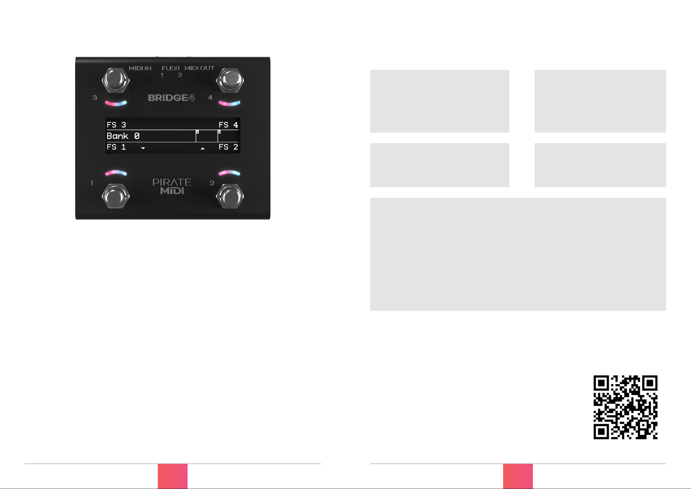
Footswitches
Four silent footswitches are the main interface on the BRIDGE4. Rated for over 100,000
presses each, they are able to send different MIDI message stacks for different press
types (Toggle On, Toggle Off, Press, Release, Double Press, Hold, Hold Release etc).
Each switch is able to send nearly 100 MIDI messages per bank:
• Toggle On: 16
• Toggle Off: 16
• Press: 8
• Release: 8
• Hold: 8
• Hold Release: 8
• Double Press: 8
• Secondary Toggle On: 8
• Secondary Toggle Off: 8
• Sequential Steps: 16
OLED Display
A large graphical display allows us to display symbols and icons to make the user
interface easier to use.
The beauty of an OLED is the crisp, high-contrast display. Easily readable from a
distance with no need for an annoying backlight.
By default, the OLED shows the bank name in the centre, and each switch label is set
to “FS ‘x”. Switch labels and bank names are editable through the onboard menus, the
web editor, and our API.
RGB LEDs
Each switch is paired with a curved light pipe that houses 2 independent RGB LEDs.
This means you can choose from millions of colours per switch and combine different
LED states/colours to create your own custom interface. Custom colours can be
created on the device, in the web editor, or sent to the device with the API.
© PIRATE MIDI 2022 www.learn.piratemidi.com
12 © PIRATE MIDI 2022 www.learn.piratemidi.com
13
QUICK START (CONT.)
need to know simple tricks & tips
•CHECK THE MIDI OUTPUTS
When you create a message, make sure you scroll across to the second/third screen
to check that the message is being sent to the correct MIDI outputs (Flexiport 1,
Flexiport 2, TRS, or USB). All outputs are on by default, but if you’re having trouble
sending messages, you should check the outputs. Read more in chapter 8.
•SET FLEXIPORT MODE BEFORE USING FLEXIPORTS
Before you plug something into a Flexiport, make sure you set the Flexiport mode in
“Menu>Global>Flexiports>Flexiport ‘x’>Mode”
You won’t get the function you want unless you set the Flexiport mode. There is no
mode set to the Flexiports by default - you must always set the mode.
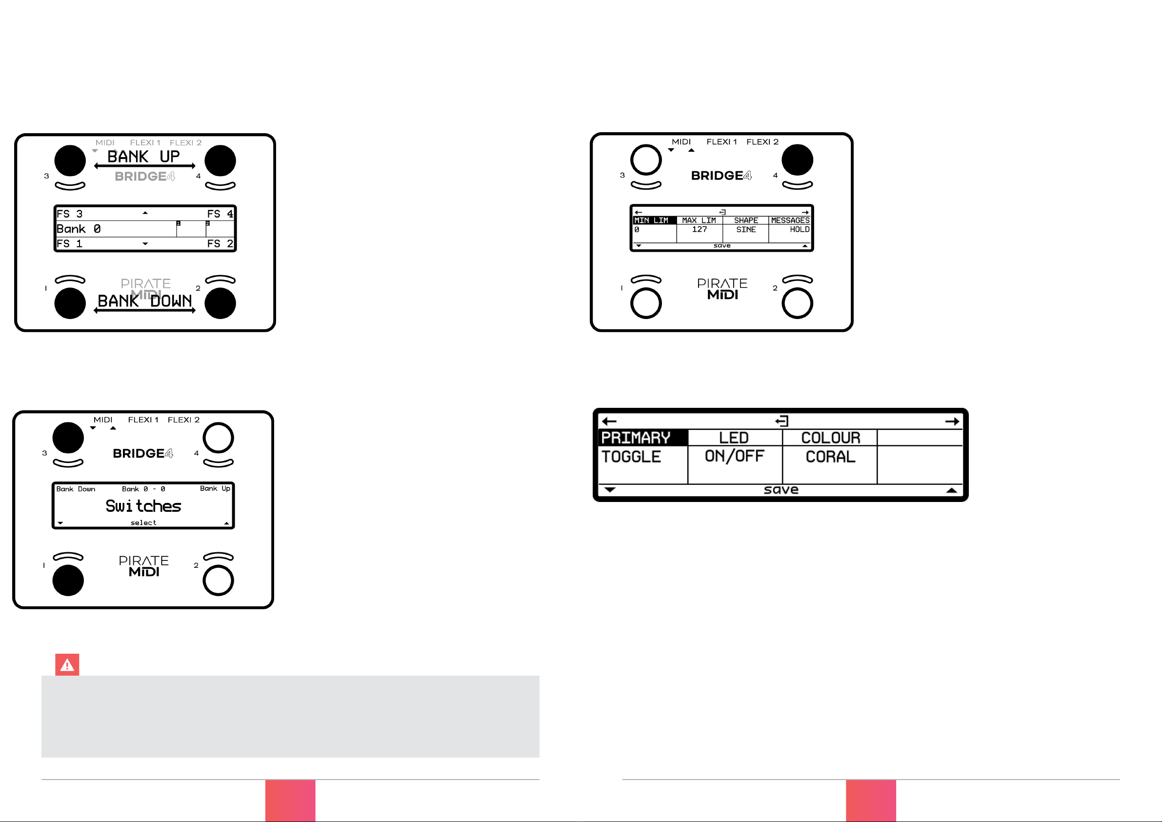
•SET BANKING PROGRAM CHANGE OUTPUTS
By default, the BRIDGE will send Program Change (PC) MIDI messages out all 4 MIDI
outputs when you change the bank (corresponding to the BRIDGE bank number). If
you want to turn some/all outputs off, or change the MIDI channel that the PC are
sent on, go to:
“Menu>Global>MIDI>Banking PC Outputs”
•SWITCH GROUPS AND BROADCAST/RESPONSE SETTINGS
When modifying switch group settings, the broadcast/response settings may seem
overwhelming. If you leave the defaults unedited, the switch will behave in a simple
“exclusive” mode where only one switch will be on at a time. If you want to learn
what these powerful settings are capable of, read more in chapter 13.
Check that your BRIDGE4 firmware is up to date. Updates are released
periodically adding new features and bug fixes. Go to: www.learn.piratemidi.
com/software/downloads