manuals.online logo
Brands
  1. Home
  2. •
  3. Brands
  4. •
  5. Befaco
  6. •
  7. Recording Equipment
  8. •
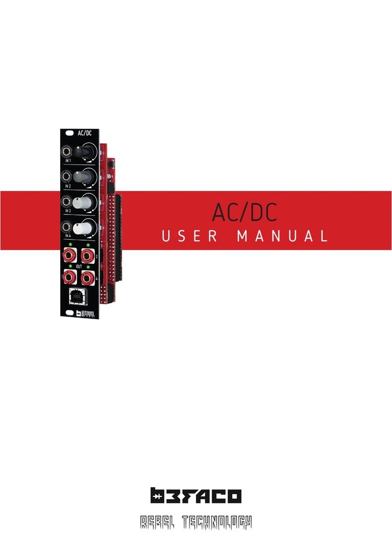
  9. Befaco AC/DC User manual

Befaco AC/DC User manual

AC/DC v1 - ASSEMBLY GUIDE
THANKS FOR CHOOSING ONE OF OUR KITS!
This manual has been written ta ing into account the common issues that we often find people experience in our
wor shops. The order in which the components are placed on the board is meant to ma e assembly as easy as possible.
Some steps are not obvious, so even if you're an experienced DIYer please read the steps thoroughly before starting.
If this is your first project, please read this article before you start assembling the it:
www.befaco.org/howto/
Some Labels are small or a bit hard to read, chec the last pages of the Build for PCB pics to help you identify
components.
OPEN BAG A
RESISTORS
It’s strongly recommended to measure the resistors with a multimeter. Color code might be hard to read with
blue/green bac ground.
Qty Value Code Name on PCB
20 560 Blue, green, blac , blac , brown R11, R16, R17, R18, R21, R22, R24, R28 , R31, R32,
R33, R35, R42, R44, R45, R48, R49, R52*, R56, R58
10 10 Brown, blac , blac , red, brown R1, R2, R3, R4, R5, R6, R8, R9, R13, R14
8 27 Red, violet, blac , red, brown R7, R10, R12, R15, R19, R20, R23, R27
8 15 Brown, green, blac , red, brown R36, R37, R39, R40, R47, R51, R53, R54
4 110 Brown, brown, blac , orange, brown R34, R41, R50, R57
4 100ΩBrown, blac , blac , blac , brown R25, R26, R29, R30
4 47ΩYellow, purple, blac , gold, brown R38, R43, R46, R55
*R52 cut these solder joints flat. There is a minijac that will be placed on top
DIODES
Solder the diodes observing heir polari y. The blac or white line on the diode must match with the white line on
the diode symbol on the PCB sil screen.
Qty Value Name on PCB
2 1N5817 D1, D2
FERRITES
Solder the two ferrite beads by using a recycled diode leg passed through each ferrite and proceed as if it were a
resistor. Ferrite beads don't have polarity.
Qty Name on PCB
2 F1, F2
1
AC/DC v1 - ASSEMBLY GUIDE
IC SOCKETS
First we will place he socke s (ta ing care to orientate them properly – the notch on one end of the soc et should
match the sil screen) and solder them into their correct positions. Get them from ICs bag.
Qty Value Name on PCB
5 DIL8 IC1, IC2, IC3, IC4, IC5
OPEN BAG B
CAPACITORS
Identifying capacitors can be quite tric y. Codes stated are indicative, please ta e a loo at this guide for help
identifying capacitors: http://www.wi ihow.com/Read-a-Capacitor
Qty Value Code Name on PCB
15 100n 104 C1, C4, C5, C8, C9, C17, C18, C23, C24, C28, C29, C30, C33, C35,
C36
12 180p 181 (blue) C15, C16, C19, C20, C21, C22, C25, C26, C31, C32, C34, C37
4 22n 220 C6, C7, C10, C11
4 1.8n 1n8J C12, C13, C14, C27
2 10uF (POLARIZED!) 10uF C2, C3
REGULATOR
Ma e sure it is positioned correctly with reference to the sil screen outline on the PCB
Qty Code Name on PCB
1 AMSR 78L05 5V_REG
SOCKET CONNECTORS
Place the soc et connectors on the control board at sil screen side, Make sure hey are s raigh . Then solder hem
Qty Size Place on PCB
1 2X4 JP8
1 2x3 JP7
2 2x5 JP10, JP11
PIN HEADERS
Place the headers on the Main board at sil screen side, Make sure hey are s raigh . Then solder hem
Qty Size Place on PCB
1 2X4 JP1
1 2x3 JP2
2 2x5 JP3, JP6
2
AC/DC v1 - ASSEMBLY GUIDE
JST CONNECTOR
Place the connector in the sil screen side.
Qty Size Place on PCB
1 1X3 MIDI
POWER CONNECTOR
Solder the power connector at “JP9”, ensuring the position is correct: it must be placed over the sil screen mar ing
with the pins facing the edge of the PCB.
XIBECA BOARD
In order to place Xibeca board properly straight, we will first place soc et connectors
in the pcb then place the Xibeca to ma e sure they are straight. Do this gen ly.
Please chec pic for orientation, placing Xibeca bac wards will destroy it.
Once all pins are in place, proceed o solder hem all.
Remove Xibeca board from he pcb o con inue wi h he assembly.
TROUBLESHOOTING
At this point we will perform a smo e test and chec that power arrives to every relevant spot in the boards. This is
very important, as testing all this once mechanical components are soldered will be hard.
This step will minimize he possibility that a mista e will destroy your Xibeca.
Connect both boards then the module to a power supply. Follow the diagram in next page to measure ALL mar ed
voltages. Use the mar ed GND spot and measure one by one the voltages. Keep in mind control board will be flipped in
order to measure the right spots.
3
AC/DC v1 - ASSEMBLY GUIDE
If your power supply behaves funny or one of the regulators get hot, unplug the module immediately. Possible errors:
- Regulator is reversed
- Reversed Diode.
- Reversed electrolytic capacitor.
- Maybe you have a bridge somewhere.
If all voltages are good ( eep in mind they might change a bit due to tolerances and your power supply) proceed with
the rest of the build.
If you are facing issues, please follow our basic troubleshooting guide: h ps://www.befaco.org/basic-
roubleshoo ing-guide/
4
AC/DC v1 - ASSEMBLY GUIDE
ICs
Place ICs in their soc ets. Ta e care of polarity, notch or dot mar orientation.
Qty Value Name on PCB
1 TL072 IC1
4 NE5532 IC2, IC3,IC4,IC5
Now we will proceed to mount mechanical components. This part of the assembly is CRITICAL. Please ta e your time
and read the following instructions carefully.
These components must NOT be soldered until they are placed on the PCB and fully attached to the front panel.
OPEN MECHANICAL COMPONENTS BAG
SPACER
Secure the 11 mm. spacer into control PCB on the component side. Mind it will be screwed to the other PCB
USB CONNECTOR
Place USB connectors but don' solder i ye .
MINIJACKS
Place mini-jac s on the PCB ensuring they are on the side with the sil screen but don' solder hem.
POTS
Place pots but do not put them all the way in, as they might short components beneath. You need to cut one of the
location lugs so they will fit in. Do no solder he po s ye !
LEDs
Place the LEDs onto the PCB minding their polarity, but don' solder hem until the front panel is in place. This is
the only way to solder them in the right position.
The long leg is the positive and the short the negative. On the PCB the square pad indicates the negative side
Qty Name on PCB
8 Green LED L2, L4, L6, L8, L9, L10, L11, L12
4 Red LED L1, L3, L5, L7
FRONT PANEL
Attach the fron panel adjusting the parts one by one if necessary until they fit. First Mini-jacks then POTS. Use
the red nuts for Outs, the smaller blac nuts for the rest of the minijac s and the larger blac ones for all pots.
Ensuring all of the above parts are flush with the panel. MIND THE POTS! So they do not touch components beneath.
Solder Mini-jac s, USB and pots.
Flip the module and ma e sure that LEDs fall flat in their holes, then proceed to solder them.
TIP: Leave pots location lugs unsoldered. Li e this you will be able to reach under the pots in case of troubleshooting.
Connect both PCBs together, then use the remaining screw to secure them. Then proceed to put in place Xibeca board.
Connect power cable ma ing sure its properly oriented.
5
AC/DC v1 - ASSEMBLY GUIDE
6

Other manuals for AC/DC

1

Other Befaco Recording Equipment manuals

Befaco STAmp 1U User manual

Befaco

Befaco STAmp 1U User manual

Befaco STEREO STRIP User manual

Befaco

Befaco STEREO STRIP User manual

Befaco NOISE PLETHORA V1 User manual

Befaco

Befaco NOISE PLETHORA V1 User manual

Befaco FX BOY User manual

Befaco

Befaco FX BOY User manual

Befaco PONY VCO User manual

Befaco

Befaco PONY VCO User manual

Befaco BURST User manual

Befaco

Befaco BURST User manual

Befaco ST AMP User manual

Befaco

Befaco ST AMP User manual

Befaco MEX V1 User manual

Befaco

Befaco MEX V1 User manual

Befaco VCMC User manual

Befaco

Befaco VCMC User manual

Befaco VCMC 1.1 User manual

Befaco

Befaco VCMC 1.1 User manual

Befaco Chopping Kinky V1 User manual

Befaco

Befaco Chopping Kinky V1 User manual

Befaco TRS User manual

Befaco

Befaco TRS User manual

Befaco FXBOY V1 User manual

Befaco

Befaco FXBOY V1 User manual

Befaco VCMC User manual

Befaco

Befaco VCMC User manual

Befaco MIDI THING User manual

Befaco

Befaco MIDI THING User manual

Befaco VCMC User manual

Befaco

Befaco VCMC User manual

Befaco HEX MIX VCA User manual

Befaco

Befaco HEX MIX VCA User manual

Befaco AC/DC User manual

Befaco

Befaco AC/DC User manual

Popular Recording Equipment manuals by other brands

Nexo NX242 Service manual

Nexo

Nexo NX242 Service manual

OHAUS SCOUT instruction manual

OHAUS

OHAUS SCOUT instruction manual

Moeller DeviceNet NZM-XDMI612 user manual

Moeller

Moeller DeviceNet NZM-XDMI612 user manual

Joemeek C2 user guide

Joemeek

Joemeek C2 user guide

Audiotrak AUDIOTRAK OPTOPlay user guide

Audiotrak

Audiotrak AUDIOTRAK OPTOPlay user guide

RCI PDD-FT-3 installation manual

RCI

RCI PDD-FT-3 installation manual

Rockwell Automation Guardmaster 440R-ENETR user manual

Rockwell Automation

Rockwell Automation Guardmaster 440R-ENETR user manual

OHAUS Scout 30268986 instruction manual

OHAUS

OHAUS Scout 30268986 instruction manual

BOSSCO Boss BE-5M owner's manual

BOSSCO

BOSSCO Boss BE-5M owner's manual

red lion KADET 2 G307K2 quick start guide

red lion

red lion KADET 2 G307K2 quick start guide

BOSSCO MICRO BR owner's manual

BOSSCO

BOSSCO MICRO BR owner's manual

foc.us Firestore FS-100 Workflow Guide

foc.us

foc.us Firestore FS-100 Workflow Guide

BOSSCO Dr. Sample SP-303 owner's manual

BOSSCO

BOSSCO Dr. Sample SP-303 owner's manual

1010music Toolbox user manual

1010music

1010music Toolbox user manual

BOSSCO EQUALIZER Maintenance manual

BOSSCO

BOSSCO EQUALIZER Maintenance manual

Blackmagicdesign H.264 Pro Operation manual

Blackmagicdesign

Blackmagicdesign H.264 Pro Operation manual

Data Video TLM-170V instruction manual

Data Video

Data Video TLM-170V instruction manual

ICON U-Solo quick start guide

ICON

ICON U-Solo quick start guide

manuals.online logo
manuals.online logoBrands
  • About & Mission
  • Contact us
  • Privacy Policy
  • Terms and Conditions

Copyright 2025 Manuals.Online. All Rights Reserved.