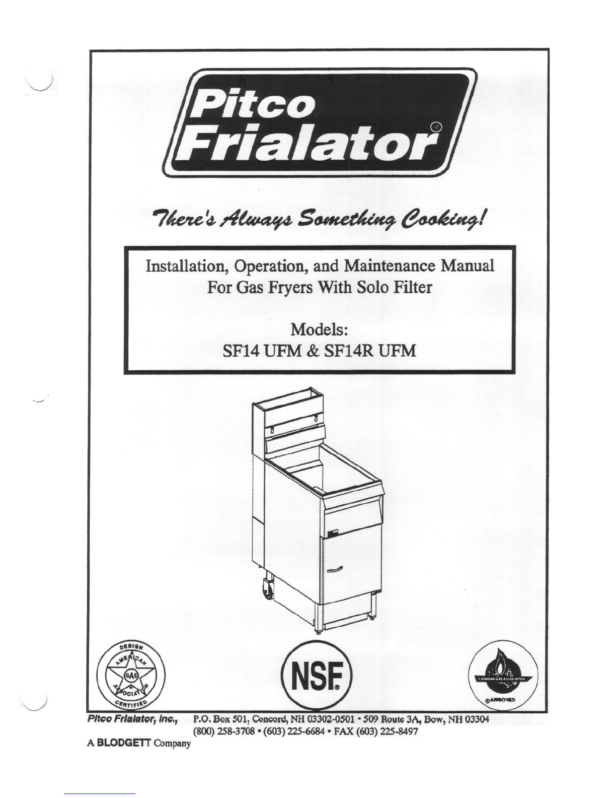
Pitco Frialator SF14 UFM Guide

v

MI'S , PF28-03
J
J
Pita>Frialator'1..20-086-01 Rev00 Rev.Due 12117/93

Therearethreedifferent typesof noti~s thatyou shouldbefamiliar with, aNO11CE,CAunON,
andWARNING. A NO11CEisaspecialnoteusedtocall attentiontoaparticularly importantpoint
CAunON isusedto point outaprocedureoroperationwhich may causeequipmentdamage. The
WARNING noticeisthemostimportantof thethreebecauseit warnsof anoperationthatmaycause
personalinjury. Pleasefamiliarize yourself with your new rooter beforeoperatingit andheedthe
noticesthroughoutthis manual. TheWARNINGS arelisted below andon thefollowing pagefor
your reviewprior to operatingtheunit
~
NonCES

SAFETY
SAFETY
Thefryer is equippedwith an oil proof, electrical supplyoordwith a three
prongsafetyplug. This is to protectoperatorsfrom electrical shockhazard
in the event of an equipmentmalfunction. DO NOT cut or remove the
grounding(dlird) prongfrom this plug.
Thereis anopenflame insidethefryer. The unit maygethot enoughto set
nearby materialsonfile. Keeptheareaaroundthefryer freefrom combus-
tibles.
DONOT supply thefryer with agasthatisDOtindicatedonthedataplate. If
youneedto convert thefryer to anothertypeof fuel, oontactyour dealer.
DONOTuseanopenflametocheckfor gasleaks!
Wait Sminutesbeforeattemptingto relight thepilot to allow for any gasin
thefryer to dissipate.
Nevermeltblocksofshorteningon
afire,andvoid yourwarranty.
WaterandshorteningDONOT mix. Keepliquids awayfrom hotshortening.
Droppingliquid frozenfoodintothehotshorteningwill causeviolent boiling.
At operatingtemperaturetheshorteningtemperaturemaybegreaterthan
3OOoP.Extremecareshouldbeusedwhenfiltering operatingtemperature
shorteningtoavoidpersonnelinjury.
;AFETY SAFETY
SAFETY
SAFETY
SAFETY
~==I
~
~==I
~~~
1~:i~:~:~::::;;11I
topof
~~~
SAFETY
SAFETY SAFETY

SAFETY
It will beeasierandsaferif thefilter assemblyhasoooledtoroomtemperature
before handlinganyfilter parts.
Ensurethatthefryer cangetenoughair to keeptheflame burning oorrectly.
If theflameisstarvedfor airit cangiveoff adangerouscarbonmonoxidegas.
CarbonMonoxideisaclearodorlessgasthatcancause
[:~:::;:::~:::;;;;III
A cookerequippedwith castersandaflexible powercord,mustbeconnected
to the gassupply with a Quick-Disconnect devi~. This quick disconnect
must comply with ANSI Z24.41. To limit the movement of the cooker
without dependingontheconnectoror quick disconnect,arestrainingcable
must alsobeinstalled.
Thepowersupplymustbe
applian~.
SAFETY SAFETY
S~FETY S:AFETY SAFETY S:AFETY
suffocation.
SAFETY SAFETY SAFETY


Section -
Safety Notice
Tableof Contents i-ii
Ust of TablesandFigures ill
WInCH FRYERDOI HAVE? 1-1
CHECKINGYOURNEWFRYER 1-2
CleckYourOrder 1-2
ASSEMBLYAND LEVEUNG 1-2
HeatDeflectorIn..ct31lation 1-2
Leveling 1-3
INSTAUA 110N ... 1-3
InstallationClearan~ 1-4
GasConnection 1-4
FuelTypes 1-4
GasLineConnection 1-5
QuickDisconnectGasConnection 1-5
FuelSupplyLineLeakandPressureTesting 1-5
ElectricalConnection... ... ... 1-5
VentilationandFireSafetySystems ~ 1-6
INl11ALADJUSTMENTS 1-7
VisualChecks 1-7
BurnerIgnitionSystems 1-8
lighting Instructionsfor ManualPilotLights 1-8
PilotFlameAdjustment 1-9
MainBurnerSystem 1-11
GasLineRequirements 1-12
BurnerAdjustment 1-12
Initial Cleaning 1-13
ThennostatCalibrationCheck 1-14
ThennostatCalibration
HighLimit Test
1.1
1.2
1.2.1
1.3
1.3.1
1.3.2
1.4
1.4.1
1.4.2
1.4.2.1
1.4.2.2
1.4.2.3
1.4.2.4
1.4.3
1.4.4
1.5
1.5.1
1.5.2
1.5.2.1
1.5.2.1.1
1.5.3
1.5.3.1
1.5.3.2
1.5.4
1.5.5
1.5.6
1.5.7
2:
f1LLING nIB FRYER 2-1
Filling theFryerWithLiquid Shortening 2-1
Filling theFryerWith SolidShortening 2-1
MELTINGSOLIDSHORTENING 2-2
2.1
2.1.1
2.1.2
2.2
Tableof Contents
Title
i

Tableof Contents(Continued)
Section ntle Page
2.3 OPERA11NGINSTRUcnONS 2-2
2.3.1 FryerStart-Up 2-2
2.3.2 FryerShutdown 2-3
2.3.3 PowerFailure ... ... "..,.. 2-3
2.4 SHORTENINGFILTERPROCEDURES.,.,." ,..",.,...,..." ,.., 2-4
2.4.1 GeneralFilterHints 2-5
2.4.2 FilterProcedures. 2-6
2.S DAn.,Y CLEANING 2-7
Fll..TERMEDIA REPLACEMENT 3-1
WEEKLY FRYERCLEANING(BOILOUT) 3-4
f1..UEINSPEC'fION ... ... 3-4
TROUBLESHOOTING 3-5
FryerTroubleshooting 3-5
FilterTroubleshooting... ... 3-6
3.1
3.2
3.3
3.4
3.4.1
3.4.2
ii

Fryer ModelInformation 1-1
VentilationandFireSafetyReferences 1-6
1-1
1-2
Figure
InsideView ofFryer 1-9
PilotAssembly,FlameAdjustment 1-9
GasVaJveShowingLocationof PressureRegulatorandPilotAdjusters 1-10
MainBurnerConditions 1-11
Air Collar 1-12
1-1
1-2
1-3
1-4
1-5
2-1
3-1
FryermustratingFilterComponents
FilterModule
List ofTablesandFigures
Title Page
iii

iv

Chapter1: GeneralInformation andInstallation
Thefrying systemyouhaveselectedfor yourestablishmentis thePita>Frialator Model SF14UFM
series.Thismodeloombinestheoonvenienceofbuilt-in filtration andthecompactnessof underfryer
filtration intooneeasytouseunit. Thisfryerwill giveyoumanyyearsofreliableserviceif youfollow
thesimpleoperationandmaintenanceproceduresin thismanual. Containedin this manualarethe
generalinstallation, operation,andmaintenanceproceduresfor theSF14UFM andSFI4RUFM.
1.1 WHICH FRYER DO I HAVE?
Therearetwomodelsavailablewith solofilters andbothcanusethesameoptions.Tofind outwhich
modelyou have,look insidethedoor attheequipmentidentification plate. This plate hasalot of
usefulinformation, buttoidentify which fryeryouhave,lookatthemodelnumberblock. Themodel
numberidentifies which fryer andwhat featuresyou have. A brief descriptionof eachmodel and
it's featuresis provided in table 1-1.
Table1-1 FryerModelInformation
1-1

1.2 CHECKING YOUR NEW FRYER
Your newfryer andit's filter havebeencarefullypackedinto onecrate. Everyeffort basbeenmade
toensurethatyour fryer will bedeliveredtoyouinperfectcondition. As youunpackyournewfryer,
inspecteachof thepiecesfor damage. If somethingis damaged,DO NOT signthebill of lading.
Contacttheshipperimmediately, theshipperis only responsiblefor 15daysafterdelivery. Check
thepackinglist enclosedwith your fryer toensurethatyouhavereceivedall of thepartstothefryer.
If youaremissing anyparts,contactthedealerfrom whomthefryer waspurchased.As youunpack
thefryer andit's accessoriesbecareful to keeptheweight of thefryer evenlydistnbuted.
To preventequipmentdamage,don'ttilt thefryer onto
anytwoof it'scastersorpull theunitby theflue vents.
Locateyour Pitco Frialator warranty andfill in theserialnumberof thefryer andthedatereceived.
Y00will fmd the serialnumberon theplateinsidethedoor. Putyour warranty cardin asafeplace
for future referen~. DO NOT returnthecardto PitcoFrialator.
1.2.1 CheckYour.
Thecratecontainingthefryerunitwill alsocontaintheitemslistedbelow
importantandMUST beretainedfor futureuse. A completedescription
containedintheShorteningFilterProcedureinChapter2.
(2)
(2)
(1)
~)
(1)
(1)
Frybasketsperfryer
PitcoOeanerSample
FilterCrumbCatch
FilterPaper
FryerCrumbScoop
HeatDeflector
1.3 ASSEMBLYANDLEVEUNG
Whenyoureceiveyourfryerit is completelyassembledwith thepossibleex~ptioDof theheat
deflector.
Youwill find a removablelabelat thereartopedgeof theunit. This labelhasinstructionsfor
positioningandinstallationof theheatdeflector.Refertothelabelandtheinstructionsbelowto
installthedeflector.
CAunON
Theseitemsarevery
of eachoomponentis
FryBasketHangerperfryer
DrainOeanOutRod
PrecoatFilterAid
OeaningBrush(Fryer)
FilterCrumbSa>op
(1)
(1)
(1)
(1)
(1)
1-2

a. Removethetwo self-drilling saews from thetop,backareaof thecooker.
b. Positiontheheatdeflectorsothatthe angledportion of thedeflector is facing towardthe
front of thefryer. Securetheheatdeflector to thebackof theunit using thesheetmetal
saews previously removed.
DO NOTobstructtheflow of combustioD/ventilationor airopeningsaround
thefryer. Adequatecl~ aroundthefryer isnecessaryfor servicing and
properburner operation. Ensurethat you meet the minimum clearances
specifiedin theinstallation instructions.
Whenproperlyinstalledtheangledsectionof theheatdeflectorwill extendovertheflue
openingto redirecttheheal It SHOUlD NOT rover theflue opening. Nothing should
block theflue opening asthis will causethe fryer to overheatandproducedangerous
gases.
Co
1.3.2. Leveling
Using anappropriatewrench andlevel ensurethat theunit is level.
a. Placethelevel acrossthefront of thetankandrotatetheadjustmenton thefront legsto
level theunit.
b. Performstepatolevel theunitfront tobackbyplacingthelevel alongthesideofthetank.
1.4 INsrAL1.ATION
Although it is poSSIblefor you to install andsetupyour newfryer, it is STRONGLY recommended
thatyou haveit doneby qualified professionals.Theprofessionalsthatinstall your newfryer will
know the local building codesandensurethat your installation is safe.
~==I
Thefryer mustbeproperly restrainedtopreventmovementor tipping. This
restraintmustpreventthefryerfrommovementsthatwould splashhotliquids
onpersonnel.This restraintmaybeanymeans(alcoveinstallation, adequate
ties,or batteryinstallation).
~:=I
1-3

Back
Sides
In additionto theclearancesrequiredfor properfryer operation,theremustbeatleast23 inchesof
Your fryer will give you peakperformancewhenthegassupplyline is of sufficient sizeto provide
thecorrectgasflow. Thegasline mustbeinstalledtomeetthelocal building codesor National Fuel
GasCode(NFPA 54-1984)andANSI Z223.1-1988LatestEdition. In Canada,install the fryer in
aax>rdancewith CAN/CGA-B149.1 or .2 andlocal codes. Gasline sizing requirementscanbe
determinedby your local gascompanyby referringto National FuelGasCode,Appendix c, Table
C-4(naturalgas)andTable C-16 (propane). Thegasline needsto be largeenoughto supply the
necessaryamountof fuel to all applianceswithout losing pressureto anyappliance. Other factors
thatareusedto determinethepiping requirementsareBTU requirementsof theappliancesbeing
oonnectedandthelengthof pipe betweenthemeter(main shutoft) andtheappliances.
[:::1
NEVER supply the fryer with a gasthat is Dotindicated on thedataplate.
Using theinoorrect gastypewill causeimproper operation. If you needto
1.4.2.1
whichthe
door.
-Eachfryer isequippedtowork with onetype of fuel. Thetypeof fuel with
intendedto operateis stampedon thedataplate attadledto theinside of the
Fuel~s
applianceis
DONOTuseanopen
Combustible
Construction
6"
6"-
N/A
Non-Combustible
Construction
6"
6"
N/A
for gasleaks!
1-4

1.4.2.2 Gas Line Connection - Connectthe fryer to the gas supply line with a oonnectorthat
amplies with theStandardfor Connectorsfor MovableGasAppliances(ANSI Z21.69-1987).If you
areinstalling afryer with castersusea quick disoonnectrefer to theQuick Disconnectinstallation
instruction, 1.4.2.3. Connectthegasline to thefryer using a pipejoint sealantthat is resistantto
liquefiedpetroleum. If thefryer wasdisoonnectedduring thefuel line testing,useasolutionof soap
andwater to leaktestthenewoonnection.
NEVERuseanadaptorto makea smallergassupplyline fit the
connedion. This may not allow propergasflow for optimum
operation,resultinginpoorcookerperforman~..
1.4.2.3 OuickDjsa)nnectGasConnection-Gasfryers
equippedwith castersmustbeinstalled with connedors
thatcomplywith theStandudfor ConnectorsforMovable
Gas Appliances, ANSI 221.69-1987, and Addenda
Z21.69A-1989. This connectionshould includeaquick
disconned device that complies with the Standardfor
QuickDisamnect Devi~ for UseWith GasFuel, ANSI
Z21.41-1989. When installing a quick disoonnectyou
mustalsoinstall ameansfor limiting themovementofthe
fryer. This devicewill preventthegasline or thequick
disronnect from beingstrained. The restrainingdevice
shouldbe attachedto the cooker on the back panelas
shownintheillustration. Thequickdisconnect,hose,and
restrainingdevicecanbe obtainedfrom your dealer.
1.4.2.4 Fuel SYR~IXLine Leak andPressureTestine -Thefuel supplysystemmustbetested
beforethefryer is used. If thefuel line is going to betestedat apressuregreaterthan(»1/2 PSIG
(3.45kPa),makesurethatthefryer is disamneded from thefuel line. If thefuel line is to betested
atapressureequalto or lessthan(s) 1/2PSIG(3.45kPa),thefryer canbeCOft-!!e-m.rlbut theunit's
gasvalvemustbeshut.Testallgasline connectionsfor leakswith asolutionofsoapandwaterwhen
pressureis applied.
1.4.3 Electrical Connection
Theelectricalservi~ usedbythefryer mustoomplywith local cx>des.If therearenolocal a>desthat
apply,refer to theNational Electrical Code(NEC) to install the servi~. In Canadarefer to CSA
StandardC22.1 andlocal codes. Wiring diagramsareprovided insidethefryer door. Thepower
requirementsfor thefryer areshownbelow.
InputVoltage
Currentperfryer
NonCE
cooker
burner
120 VAc, 60Hz
7Amps 220(or 240)VAc, SOliz
3.sAmps
1-5

Thefryer isequippedwith anoil proof, threeprong(grounding)plugforyour
protectionagainstelectricalshockhazardintheeventofequipmentmalfunc-
tion. DO NOT cutorremovethegrounding(third)prongfrom thisplug. This
plug must bepluggedinto aproperly groundedthreeprong receptacle.
The fryer has one power supply for the fryer controls andthe filter module. The fryer must be
groundedin accordancewith localcode;if thereis notalocalcode,comply with NBC ANSI/NFPA
No. 70-1990. The fryer shouldbepluggedinto areceptacleatall timesto keeppowersuppliedto
thefilter line heattape.
1.4.4 VentilatioD and Fire Safety Systems
Your new fryer must have proper ventilation to function safely and properly. Exhaust gas
temperaturescan reachashigh as1200°F. Therefore, it is very important to install a fire safety
system.Your ventilation systemshouldbedesignedto allow for easycleaning. Frequentcleaning
of theventilation systemandthefryer will reducethechan~ of fire. Table 1-2providesalist of
referen~ documentsthat provide guidanceon ventilation andfire safetysystems.This tableis not
necessarilycomplete. Additional information canbeobtainedfrom theAmericanGasAssociation,
8501EastPleasantValley Road,Ceveland, OH 44131.
Table 1-2. Ventilation andFire SafetyReferen~s
~=:I
1-6

Excessiveventilation causesdrafts,which will interferewith theproperoperationof thepilot and
theburner. Leaveatleast18inchesof openspacebetweenthefryer'sflueventopeningandtheintake
of theexhausthood.
Ensurethatyourventilation systemdoesnotcauseadowndraft atthefryer's
flueopening.Downdraftswill notallow thefryer toexhaustproperly andwill
causeoverheatingwhich maycausepermanentdamage.Damagecausedby
downdraftswill not becoveredunderequipmentwarranty. NEVER allow
anythingtoobstrud theflow of combustiblesorventilation exiting from the
fryer flue. DO NOT put anything on topof the flue area.
NEVER connecttheblower directly totheflue openings. Thedirect flow of
airwill causepoortemperaturerecovery,poor ignition, inefficient operation
of thefryer, andcould extinguish thepilot.
1.5 INI11ALADJUSTMENTS
After your fryer hasbeeninstalledasdescribedin section1.4,it needsto beadjustedtoensurethat
it will perform asdesigned. Theseadjustmentsmust be performed by a qualified person. To
perform theseadjustmentthefollowing toolswill beneeded:
.Manometer(low pressuregauge) .Digital Thermometer(Temperatureprobe)
.DC Millivolt Meter
1.5.1 Visual Checks
Beforeyou beginfilling andadjustingthefryer, perform thefollowing visual
checks:
After thefryerisin itspermanentlocation,checkfor levelness.Any
additionalleveling thatisnecessarycanbeperfonned asdescribed
in section1.3.
a.
b. Oleck thetemperaturebulbs(thennostat/high-limit), locatedin the
fryer tanktoensurethatthemounting screwsaretight Thefigure
showstheprobetypicallocation. Look downinsidethefryer tanks EnsuretIIIt Un. pen-
to seetheprobes. 8,.Nt 1_.
CAU'I10N
NonCE
1-7

Beforegoing anyfurther,fill thefryer with WATER. Water is usedfor the
installation adjustments becausethe temperaturewill neverexceed212°F
(100°C)therebyallowingplentyof adjustmenttime. Neverletthewaterlevel
gobelow theOIL LEVEL mark on therearof thetank.
Thereis anopenBameinsidethefryer. Theunit may gethot enoughto set
near by materials on fire. Keep the area around the fryer free from
1.5.2.1 Li~htin& Instroctions for Manual Pilot l1ihts -To light thepilot light referto these
instructionsandFigure1-1. Thenumbersin parenthesisreferto Figure1-1callouts.
Wait 5 minutesbeforeattemptingto relight thepilot to allow for anygasin
thefryertodissipate.
a. Openthegassupplyvalvestothefryer.
b. Openthefryer'sdoortogainaccessto thecontrols. Turn thethermostatcontrol knob
counterclockwiseto theoff position.
TurntheUnitrol gasvalveknob (tanknob) (2)tothePll..OT positionand
pushin on the knob. Hold the knob in for approximately oneminute to
purgetheair out of theline. Hold aflame tothepilot light until thepilot
(3) ignites. This maytate alittle while thefirst time you light thefryer
becauseof air in thelines. Oncelit, hold theknob in for approximately
60secondsandthenrelease.
c.
d. If diepilot goesoutwait 5minutesandrepeatstepc. If afterthreetriesthepilot will not
remainlit, refer to theoperatortroubleshootingsectionof this manual.
e. TurntheUnitrolgasvalveknob(tanknob)counterclockwisetotheON
position.
f. Setthethermostatcontrolknobtothedesiredtemperaturesetting.
CAtmON
G;:a
G:::I
(1)
(lJ0 ~
~ ~
~~
1.8

g. Themainburner(4)will light andbecontrolledby thethermostat.Thepilot burnerwill
remain lit regardlessof the switch position.
1.5.2.1.1 Pilot Flame Adiustment - The pilot flame should be adjustedto prod~ the ~r
millivolt outputfrom thepilot sensingdevi~. Millivolt outputfor thethermopileshouldbebetween
300 and500 millivolts. Figure 1-2 showsthepilot assemblywith examplesof the incorrect and
correctpilot size. ExampleA illustrates a pilot flame sizethat is too small to produ~ sufficient
millivolt output. Example B is thecorrect sizefor propermillivolt output
TME~ll£ \
PILOTIUDU \ \ M
B
A
Figure1-2 PilotAssembly,
1-9

a. This testrequires aDC millivolt metersetto a scaleof O-l(XK)mv.
b. Locatethethermopile wirescomingfrom thethermostat!HighLimit boxgoingtothegas
shutoff valve. The wire insulationsizedecreasesnearthegasvalve connections.
Connectthenegative(-)testprobetopilotbracket.
Connectthepositive(+)testprobetooneof theHighLimit terminal
Removethepilot flameadjustmentcover.
PRESSURE REGULATOR
(UNDER CAP SCREW)
Co
d.
e.
PILOT ADJUSTER LOCATION
(UNDER CAP SCREW)
g. Rotatethescrewin thedirectiontoachieveareadingof400rlO mvfor thermopiles.
h. Replacethepilot flameadjustingscrewcover.
LOCATION
NonCE
1-10
This manual suits for next models
1
Table of contents
Other Pitco Fryer manuals

Pitco
Pitco VF35 User manual

Pitco
Pitco SGH50 User manual

Pitco
Pitco 14T User manual

Pitco
Pitco E14X User manual

Pitco
Pitco SG Series Owner's manual

Pitco
Pitco SOLSTICE SUPREME SSH User manual

Pitco
Pitco SELV Series User manual

Pitco
Pitco SG18WKS User manual

Pitco
Pitco SG14TS User manual

Pitco
Pitco E14B Instruction Manual