FKI Friomat FKE 169 EG User manual

1
User Manual for Friomat fryer
Floor model
Version 6.0 –OKT 2016

2
Table of contents
1Introduction........................................................................................................... 3
2In general.............................................................................................................. 3
2.1 Manufacture .....................................................................................................3
2.2 The name of the machine...................................................................................4
2.3 Machine tag .....................................................................................................4
3Outline and utilization .............................................................................................4
3.1 General description ...........................................................................................4
3.2 Purpose og the machine and intended utilization...................................................4
3.3 Warning of foreseeable mistreatment ..................................................................4
3.4 Technical specifications and consumption.............................................................5
4Safety and risk.......................................................................................................6
4.1 Safety instructions, built in.................................................................................6
4.2 Precaution........................................................................................................ 6
5Operation .............................................................................................................. 7
5.1 Start-up...........................................................................................................7
5.2 Fryer equipped with automatically lift system .......................................................7
5.3 Fryer equipped with oil cleaning system...............................................................7
5.4 Encoding.......................................................................................................... 8
5.4.1 Encoding of times for deep frying .................................................................. 8
5.4.2 Encoding the temperature ............................................................................8
5.5 Factory settings ................................................................................................9
6Storage, transportation and installation ..................................................................... 9
6.1 Installation....................................................................................................... 9
6.2 General ...........................................................................................................9
6.3 Fixing ..............................................................................................................9
7Maintenance, troubleshooting and repair.................................................................. 10
7.1 Cleaning ........................................................................................................ 10
7.2 Trouble shooting ............................................................................................. 12
8Termination ......................................................................................................... 12
8.1 Destruction .................................................................................................... 12
9Specifications for spare parts ................................................................................. 13
10 Wire diagram .................................................................................................... 15
11 EC Declaration of Conformity............................................................................... 21

3
1 Introduction
Original instruction manual
This guide is a translation of the original instructions manual of FKI for the Friomat Fryer
- Floor model.
Purpose
The purpose of this manual is to ensure proper installation,use, handling and
maintenance of the fryer.
Accessibility
The instruction manual must be kept - to the staff - in a well-known place which is easy to access
for electricians and personnel who maintain.
Knowledge
The employer is obligated to ensure that people who operate, serve and maintain the fryer, has
read the instruction manual or as a minimum are familiar with the parts which are relevant to
their job.
Furthermore everybody who operates, serve and maintain the fryer is obligated to seek.
information in the operation instructions manual.
2 In general
2.1 Manufacture
The fryer is produced by:
FKI Fast Food Teknik A/S
Byghøjvej 5, Verninge
DK - 5690 Tommerup

4
2.2 The name of the machine
The name of the Friomat fryer is FKE followed by 3 or 4 digits and 2 letters. The first and the
second digit marks the size of the vessel (contents of oil) in litres. The third and the forth digit
marks the power in each heat section in kW.
The letters mark model EG = single floor and DG - double floor.
Furthermore each heat section is called VSFK followed by digit which is equal to the
description of the fryer.
2.3 Machine tag
The machine tag is placed on the back og the machine.
3 Outline and utilization
3.1 General description
The Friomat fryer is the full electronic programmable fryer which is easy to operate and maintain.
It has deep vessels which make splash screens unnecessary. The powerful heat elements and
the electronic heat sensor cause the oil immediately to warm up. The Friomat fryer is easy to
clean. The temperature of the oil is shown on a display which has up to 6 different programmable
frying times. Furthermore a lift system and an oil cleaning system can be installed as part of the
fryer.
3.2 Purpose og the machine and intended utilization
The fryer is designed for deep-frying defrosted as well as frosted products minded for deep-
frying in oil/deep fat.
3.3 Warning of foreseeable mistreatment
The Friomat fryer must not be used for anything other than deep-frying food products.
5
3.4 Technical specifications and consumption
Fysiske dimensioner
Model
Width x Depth x Height
Liter
Weight in kilo
FKE 169 EG
350 x 650 x 880 mm
16
53
FKE 1615 EG
350 x 650 x 880 mm
16
53
FKE 2515 G
500 x 650 x 880 mm
25
80
FKE 2521 G
500 x 650 x 880 mm
25
80
FKE 2010 G
415 x 650 x 880 mm
2x10*
80
FKE 2014 G
415 x 650 x 880 mm
2x10*
80
FKE 169 DG
700 x 650 x 880 mm
2x16
80
FKE 1615 DG
700 x 650 x 880 mm
2x16
80
FKE 1621 DG
700 x 650 x 880 mm
2x16
80
FKE 3629 TG
760 x 650 x 880 mm
1 x 16
2 x 10*
95
FKE 3619 TG
760 x 650 x 880 mm
1 x 16
2 x 10*
95
*seperate vessels
Electricity
The Friomat fryer must be connected and ground fault current through connector.
Power: 3 x 400 V AC or 3 x 230 V AC (Norway) Frequency:
50/60 Hz
Interference
Airborne interference caused by the friomat fryer:
Measured sound pressure level dB(A): < 45

6
Absorbed power
Typebetegnelse
Varmesektion
Tilslutnings-
spænding
Optagen
effekt
Optagen
strøm
Min. sikring
i installation
FKE 169 EG
VSFK 169 G
400 V
9kW
13,0 A
16 A
FKE 169 EG
VSFK 169 G
3 x 230 V
9kW
22,6 A
25 A
FKE 1615 EG
VSFK 1615 G
400 V
15kW
21,6 A
25 A
FKE 1615 EG
VSFK 1615 G
3 x 230 V
15kW
37,6 A
40 A
FKE 1621 EG
VSFK 1615 G
400 V
21KW
30,3 A
32 A
FKE 2515 G
VSFK 2515 G
400 V
15kW
21,6 A
25 A
FKE 2515 G
VSFK 2515 G
3 x 230 V
15kW
37,6 A
40 A
FKE 2521 G
VSFK 2521 G
400 V
21kW
30,3 A
32 A
FKE 2010 G
VSFK 2010 G
400 V
10kW
21,6 A
25 A
FKE 2010 G
VSFK 2010 G
3 x 230 V
10kW
37,6 A
40 A
FKE 2014 G
VSFK 2014 G
400 V
14kW
30,3 A
32 A
FKE 169 DG
VSFK 169 G
400 V
2x9kW
13,0 A
16 A
FKE 169 DG
VSFK 169 G
3 x 230 V
2x9kW
22,6 A
25 A
FKE 1615 DG
VSFK 1615 G
400 V
2x15kW
21,6 A
25 A
FKE 1615 DG
VSFK 1615 G
3 x 230 V
2x15kW
37,6 A
40 A
FKE 1621 DG
VSFK 1621 G
400 V
2x21KW
30,3 A
32 A
FKE 3629 TG
VSFK 1615 G
VSFK 2014 G
400 V
1x15KW
1x14KW
21,6 A
30,3 A
25 A
32 A
FKE 3619 TG
VSFK 169 G
VSFK 2010 G
400 V
1x9KW
1x10KW
13 A
21,6 A
16 A
25 A
Please notice that Friomat fryers in double version are equipped with two heat sections.
4 Safety and risk
4.1 Safety instructions, built in
The heat section has a built-in magnet switch which cuts off the power to the heat elements when
the heat section is raised from the worktop.
The electronically control is equipped with an acoustics alarm which is activated, if any
temperature above 250°C is recorded.
4.2 Precaution
The heat section has a built-in mechanical safety thermostat which disconnects the power, if the

7
temperature exceeds 245°C. The thermostat is reconnected when the temperature drops. Press
the red button which is placed on the side of the heat section. The electroni- cally control is
equipped with a fuse which protects the control from overload. The fuseis placed under the front
panel which contains the display.
5 Operation
Adding oil
Turn off the fryer. Never add oil or deep fry fat when the fryer is switched on. The oil/deep
fry fat can be ignited if it hits the heat elements. Heavy smoke can also occur.
Remove the lid and the basket. Add oil or deep fry fat to the MAX-tick. Yet as a minimum to
the tick inside the vessel (at the back).
NB! If the fryer is equipped with a pump for oil cleaning, it is only allowed to use oil
- NEVER deep fry fat.
5.1 Start-up
The main switch which is placed on the back of the heat section is turned to ON. A dot will
occur in the lower right corner of the display which indicates that the power is on.
Press ON at the keyboard to activate the fryer. The fryer will start in Standbymode
and heat up to the pre-set Standby temperature.
As long as the temperature is below 50°C, tree dashes will be shown in thedisplay. When
the temperature is above 50°C the actual temperature will be measured by the heat sensor
in the oil and shown in the display.
Press + to change to normal mode and the fryer will continue to heat to the pre-set
operation temperature. When the temperature is reached the fryer is ready.
Place the baskets on the bracket atthe heat section. Place the requested products in the basket
and steady lower it into the oil.
Press a key 1-6 depending on the requested deep-frying time. The display will show the chosen
time in minutes and 1/10 minutes. The time will be counted backwards which means that the
remainingtime is shown at any time.
When time expires an acoustic alarm will sound in approx. 2 sec., and the basket is
removed from the oil. Leave it hanging in the bracket, so the excess oil/deep fry fat can
drain.
A program in progress can be stopped by pressing the Reset button.
5.2 Fryer equipped with automatically lift system
See separate guide.
5.3 Fryer equipped with oil cleaning system
See separate guide.

8
5.4 Encoding
All encoding must be done in Standby mode. Raise the heat section,so the heat elements
are disconnected by the magnetic switch before the fryer is activated by pressing ON.
5.4.1 Encoding of times for deep frying
Press [2] and hold for more than 6 sec. The programming menu 2 will appear in the display.
Press the number of the program (1-6) on which you want to modify thetime.
The time is changed by pressing [+] or[-].
The program returns to menu after 5 seconds, and the modified time issaved.
Toexit the menu, press RESET.
5.4.2 Encoding the temperature
Press [3] and hold for more than 6 sec. The programming menu 3 will appear in the display.
Press [1] to change the Standbytemperature.
Press [2] forthe change in operatingtemperature.
Tochange the temperature press [+] or[-].
The program returns to menu after 5 seconds, and the modified timesaved.
Toexit the menu, press RESET.

9
5.5 Factory settings
6 Storage, transportation and installation
6.1 Installation
The machine must be wired by a certified electrician.
Be aware that the installation is done properly with adequate security size andprotection against
fault currents and earth. The fryer must be connected 400V + 0 + J or 3 x 230V in Norway.
Please notice that there must separate connection to each heat section.
6.2 General
Floor models are standard equipped with front legs and fixed wheels at the rear. There should be
space in front of the fryer, so it is possible to pull it out from the wall for cleaning and maintenance.
Alternatively: fryer also available with 4 wheels, wher the front wheels can be locked (optional).
6.3 Fixing
For ships the fryer can be delivered with fixed legs and bracket for attachment to the floor.
Program 1
3 min.
Program 2
12 min.
Program 3
15 min.
Program 4
3 min.
Program 5
12 min.
Program 6
15 min.
Standby temperature
130°C
Operating temperature
180°C

10
7 Maintenance, troubleshooting and repair
7.1 Cleaning
The fryer should be cleaned daily.
Sluk frituren og lad den køle af. Hvis er er
hæv/sænk på frituren sættes aktiveres stand
by, hvorved kurvene kører ned. Åben
aftapshanen og lad olien løbe ned i
aftapsspanden.
Remove the baskets and the brackets. These
can be cleaned e.g. in a dishwasher
Lift the heat section and tip it back
Ensures that the heating sector hangs
properly

11
Never use cleaners on the parts that are in
contact with food. If it is still necessary, make
sure the parts are thoroughly rinsed and dried.
Dry the heat section with a damp cloth.
Pay special attention to the area around the
micro switch. It is important to clean
thoroughly here.
Wipe the edges of the fryer with a damp
cloth
Place the baskets into place again.
Open the door, pull the drawer out and clean
the filters and bucket

12
7.2 Trouble shooting
The electronically control of the fryer is equipped with a fault reporting which can be read
in the display if any malfunctions of the heat sensor should occur.
In that case the fryer will not start when pressing ON and a code will appear in the display.
1. Code ”1”: The sensor for the temperature is short-circuited.
2. Code ”2”: The sensor for the temperature is not connected or has been cut off.
Call upon service.
.
8 Termination
8.1 Destruction
The machine is marked with the above recycling symbol
(EC Directive 2002/96/EC) and must be disposed in
accordance with your country order.
This means that when the product becomes obsolete, you
should dispose it after the local municipality’s rules, e.g.
in unsorted waste stream.
13
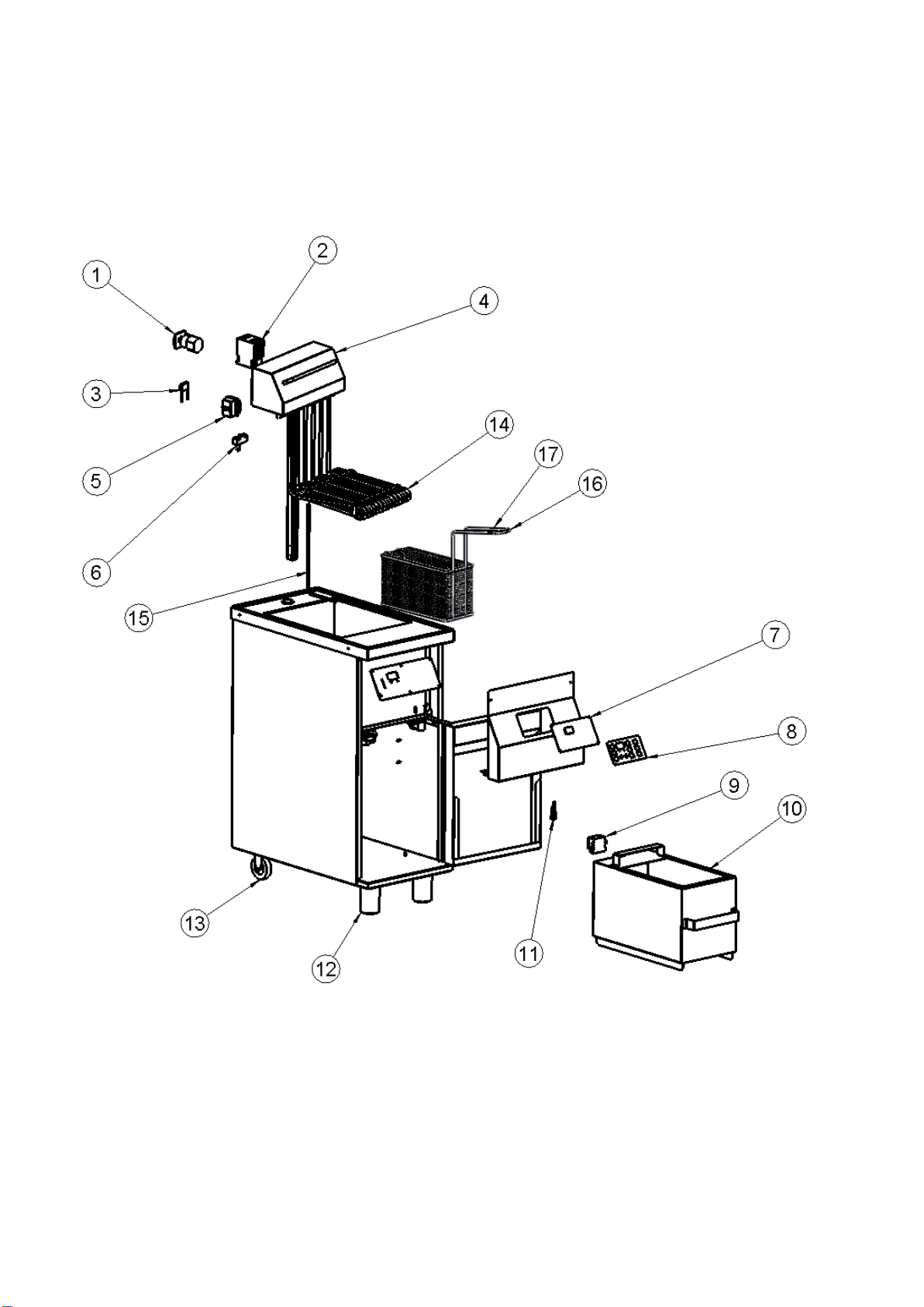
9 Specifications for spare parts
FKE 16/20/25/36

14
Pos.
Item number
Description
1
84-00068
POWER SWITCH 4-POL CA20 25A
1
84-00067
POWER SWITCH 4-POL CA20 32A
2
88-00080
CONTACTOR 3-POL 230V 20A
2
88-00066
CONTACTOR 3-POL 230V 32A
3
84-00288
KONDENSATOR
4
84-16901
HEAT SECTION FKE 169/3619 230V COMPLET
4
84-16902
HEAT SECTION FKE 169/3619 400V COMPLET
4
84-16974
HEAT SECTION FKE 1615/3629 230V COMPLET
4
84-16905
HEAT SECTION FKE 1615/3629 400V COMPLET
4
84-16908
HEAT SECTION FKE 1621G 400V COMPLET
4
84-16914
HEAT SECTION FKE 2010G 400V COMPLET
4
84-16915
HEAT SECTION FKE 2014G 400V COMPLET
4
84-16907
HEAT SECTION FKE 2515G 400V COMPLET
4
84-06906
HEAT SECTION FKE 2521G 400V COMPLET
5
72-03615
SAFETY THERMOSTAT
6
83-10003
MICRO SWITCH FKE
7
84-16500
PRINT FRIOMAT
8
84-16400
KEYBOARD FKE- SERIE 6-PRG.
9
83-09056
TRANSFORMER 240V/12V
10
15-00021
DRAIN BUCKET FKE 16DG 20/25 and 36
10
84-00112
DRAIN BUCKET FKE 16 EG
11
84-00290
FUSE HOLDER
12
83-07544
FEET ADJUSTABLE
13
83-07633
WHEEL 75 mm
14
84-00057
HEAT ELEMENT FKE-G 3kW/230V (Norge)
FKE 169/3619
14
84-00062
HEAT ELEMENT FKE-G 5kW/230V (Norge)
FKE 2010/1615/2515
14
84-00056
HEAT ELEMENT FKE-G 3kW/400V
FKE 169/3619
14
84-00061
HEAT ELEMENT FKE-G 5kW/400V
FKE 2010/1615/2515/3629
14
84-00072
HEAT ELEMENT FKE-G 7kW/400V
FKE 2014/1621/2521
15
83-10002
SENSOR FK16-G PT100 kl B 3-LEDER
16
82-00071
BASKET 1/2 FKE16-
17
84-00070
BASKET 1/1 FKE16-
15
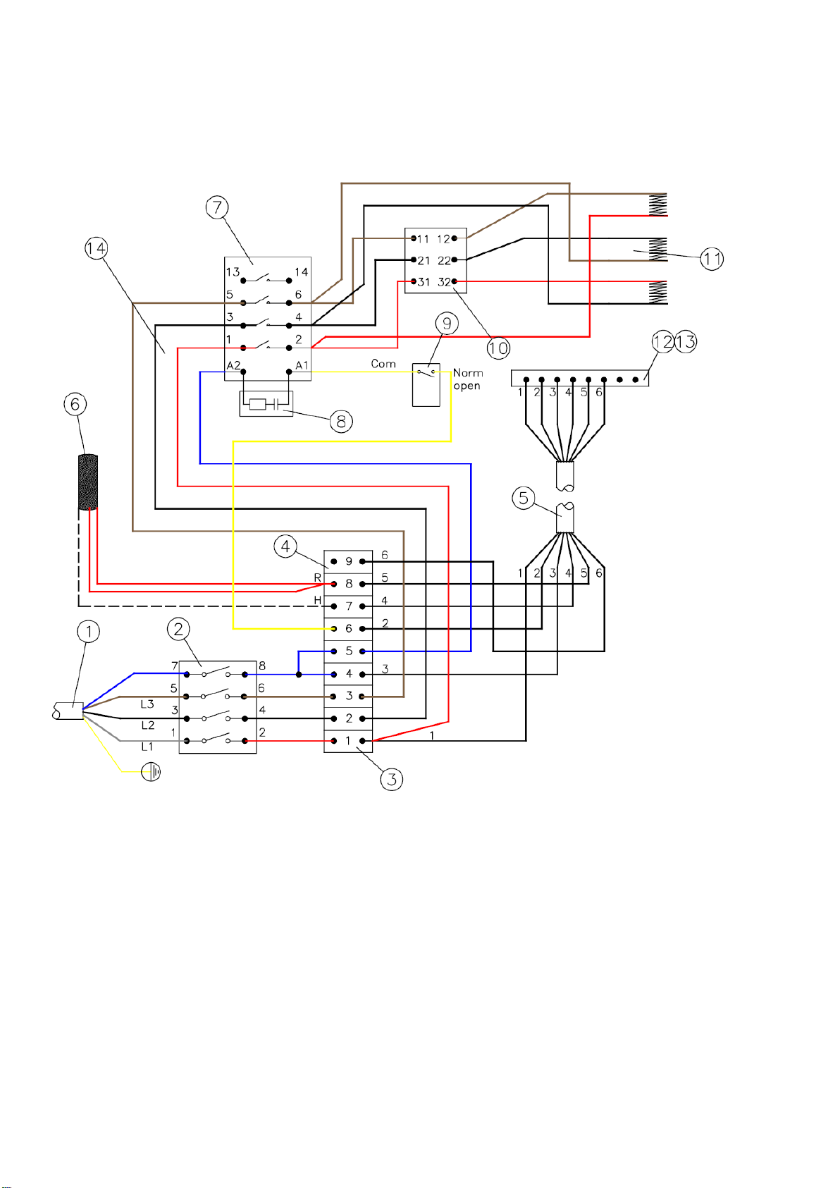
10 Wire diagram
FKE HEATING SECTION VSFK 16- OG 25-SERIES

16
Pos.
Item number
Description
1
72-03674
CABEL 5G2,5mm2
2
84-00068
POWER SWITCH 4-POL CA20 25A
2
84-00067
POWER SWITCH 4-POL CA25 32A
2
84-00105
POWER SWITCH CA40 40A
3
83-07608
TERMINAL BLOCK 6 MM²
4
83-07952
TERMINAL BLOCK 2,5 MM²
5
72-03675
CABEL 7G1,0mm2
6
83-10002
SENSOR FK16-G PT100 kl B
7
84-00080
CONTACTOR 3-POL 230V 20A
7
84-00066
CONTACTOR 3-POL 230V 32A
7
84-00553
CONTACTOR 3-POL 230V 40A
8
84-00288
CAPACITOR 0,22uF
9
83-10003
MICRO SWITCH FKE
10
72-03615
SAFETY THERMOSTAT
11
HEAT ELEMENT (SEE SPARE PARTS LIST)
12
84-00180
PLUG FOR MULTI PLUG, HUN
13
84-00183
CABLE BOX STRAIGHT FOR CHASSIS
14
81-05560
COMPLETE WIRING
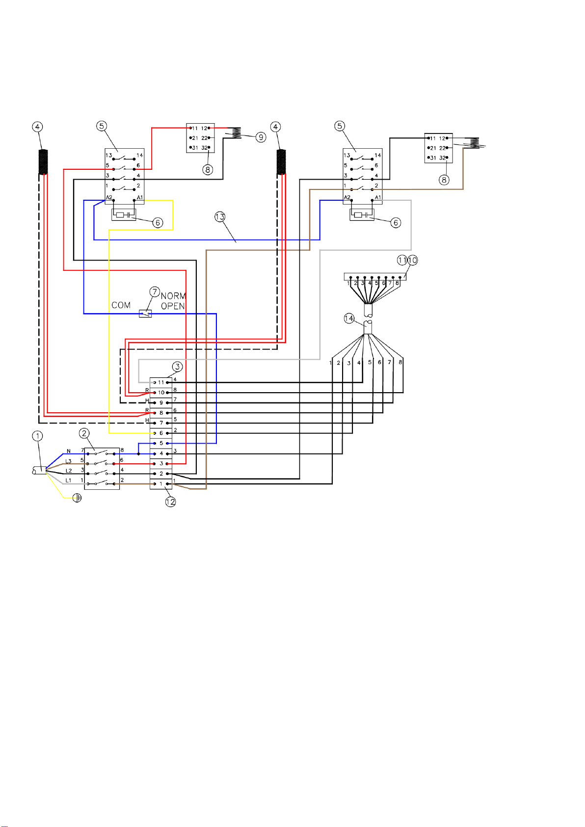
17
HEATING SECTION VSFK FKE 20-SERIES

18
Pos.
Item number
Description
1
72-03530
CABEL 5G2,5mm²
2
84-00068
POWER SWITCH 4-POL CA20 25A
3
83-08156
TERMINAL BLOCK 3-POL 2,5mm²
4
83-10002
SENSOR FK16-G PT100
5
88-00080
CONTACTOR 3-POL 230V 20A
6
84-00288
CAPACITOR 0,22uF
7
83-10003
MICRO SWITCH FKE
8
72-03615
SAFETY THERMOSTAT
9
84-00061
HEAT ELEMENT FK GULV 5kW/400V
9
84-00072
HEAT ELEMENT FK GULV 7kW/400V
10
84-00181
LINER FOR CHASSIS
11
84-00183
CABLE BOX STRAIGHT FOR CHASSIS
12
83-08156
TERMINAL BLOCK 6 mm²
13
81-05560
COMPLETE WIRING
14
72-03680
CABLE 12G1,0mm2
19
Front FKE 16- og 20 series
Pos.
Item number
Description
1
84-00181
LINER FOR CHASSIS
2
84-00182
TERMINALS FOR MULTI CONNECTOR,
ANGLE
3
83-08156
TERMINAL BLOCK 2,5mm²
4
84-00290
FUSE HOLDER
5
72-00130
MINIATURE FUSE 7A
6
84-16500
PRINT FKE HEATER CONTROL
7
83-09256
TRAFO 230/12V

20
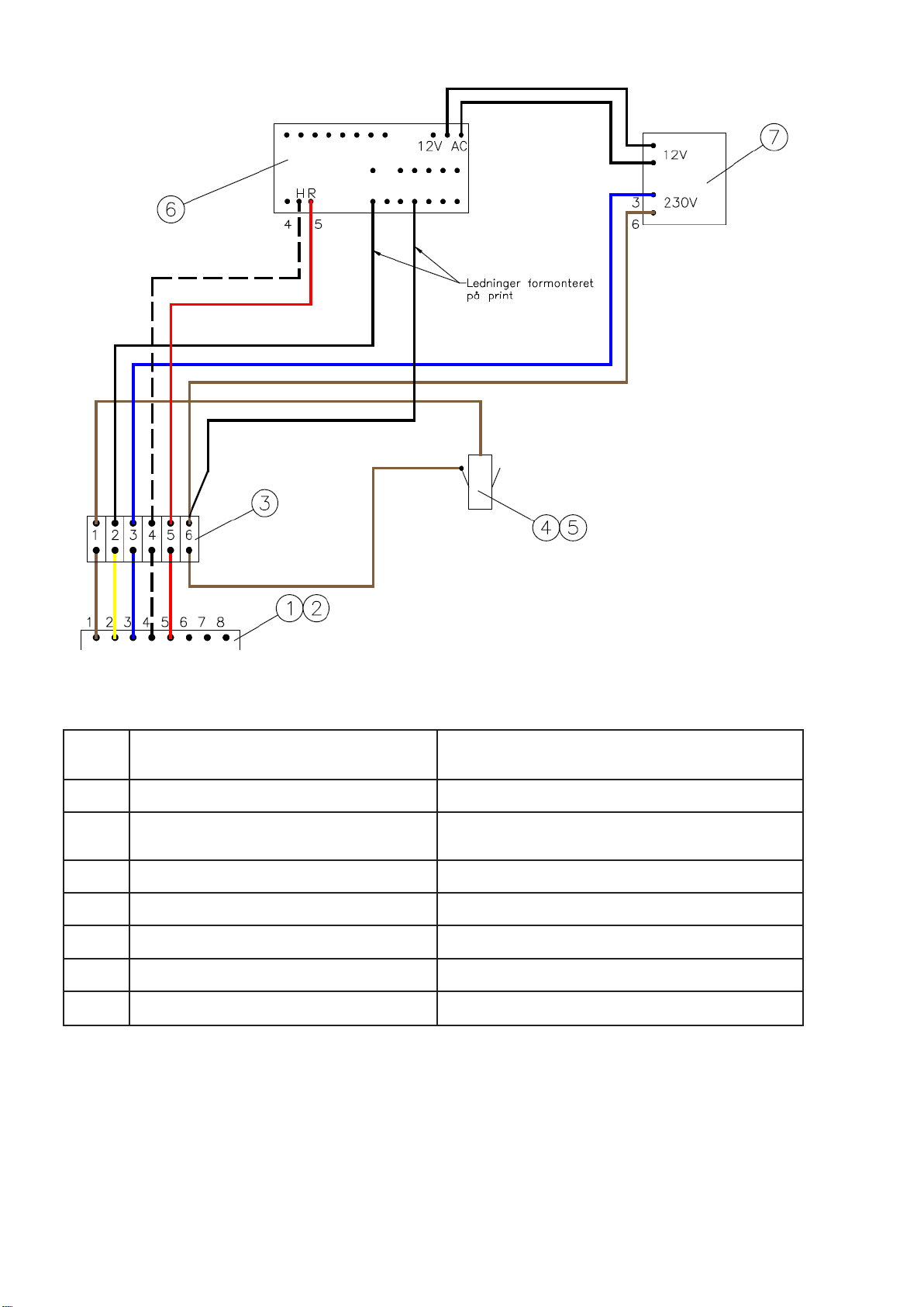
Front FKE 20-series
Pos.
Item number
Description
1
83-08156
TERMINAL BLOCK 2,5mm²
2
84-16500
PRINT FKE HEATER CONTROL
3
83-09256
TRAFO 230/12V
4
84-00290
FUSE HOLDER
5
72-00130
MINIATURE FUSE 7A
This manual suits for next models
10
Table of contents
Other FKI Fryer manuals


Popular Fryer manuals by other brands

Fritel
Fritel Snacktastic 5801 user manual

Hamilton Beach
Hamilton Beach 35033C Use & care guide

Tower Hobbies
Tower Hobbies T17061BLK user manual

Tesla
Tesla AirCook & Grill QG800 WiFi manual

Gourmia
Gourmia GAF685 user manual

Mondial Designs Limited
Mondial Designs Limited FAST FRY PREMIUM Instruction and Technical Service Manual


