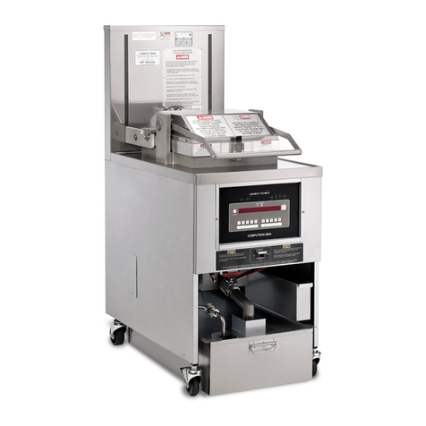
Pitco TURBOFRY 2000 User manual

~
C
~~IIII_III~
~
'.IIIII~
~
c
~
~+IIII_.
'1II"I~
Literature# L20-150Rev1
Printed23October1996
V tfl ~,-C'I)'
Ct? /" ~
I~I! -JQ:L-",-
I, ~
,
~ \'c~,_D B
PatentPending Manufacturedin
TheUnitedStatesof America


FOR YOUR SAFETY:
Donotstoregasolineor otherflammablevapors
or liquids in the vicinity of thisor anyother ap-
pliance.
TO THE PURCHASER
POST IN A PROMINENT LOCAllON IN-
STRUCTIONS TO BE FOLLOWED IN THE
EVENT THAT AN OPERATOR SMELLS
GAS.OBTAIN THIS INFORMAnON FROM
YOUR LOCAL GAS SUPPLIER.
WARNING
This applianceis equipped with athreeprong (ground-
ing) plug. This is for your protection againstshockhaz-
ardin theeventof equipment malfunction. Always plug
the unit into a properly grounded three-prong recep-
tacle. 00 NOT cut or remove the grounding (third)
prong.
WARNING
00 NOT use an open flame to check for gas leaks!
Keepall openflamesawayfromthemachineatall
times.
WARNING
Machines equipped with castersand a flexible power
cord. must be connected to a gassupply with a Quick-
Disconnect device. This quick disconnect must com-
ply with ANSI Z24.41. To limit the move~nt of the
unit without depending on the connector or quick dis-
connect. a restraining cable must also beinstalled.
WARNING
There is an open flame inside the machine. The unit
maygethotenoughto setnearbyma1erialsonfire. Keep
the areaaround the unit free from combustibles.
WARNING
Useonly aB/C or AlBIC extinguisher thatcontains the
dry chemical Sodium BicartxJna1eor Potasium Bicar-
bonateshould be usedto extinguish any fires.
WARNING
Ensurethat the machine cangetenough air to keepthe
flame burning COn'ectly.If theflame is starvedof air it
cangive off adangerouscarbonmonoxide gas.Carbon
Monoxide is a clear odorlessgasthat can causesuffo-
cation.
WARNING
CarbonMonoxide gascanbuild up if you obstruct the
flue. Blocking the flue will alsocausethe unit to over-
heat.00 NOT obsttuct the flow of combustion/venti-
lation or air opening around the machine. Ensure that
you meet the minimum clearancesspecified in the in-
stallation insttuctions. Adequateclearance around the
unit is necessaryfor servicing and proper burner op-
eration.
WARNING
If themachine should shutdown unexpectedly wait 5
-- -
minutesbeforeattemptingtorestartit. This will allow
for anyexcessgasin theunittodissipate.
WARNING
Thepowersupplymustbedisconnectedbeforeservic-
ingorcleaningtheunit.
WARNING
DO NOT supply the fryer with agasthat is not identi-
fied on the data plate, locatedon the inside of one of
the doors of the machine. If you need to convert the
machineto another type of fuel, contact your dealer or
Authorized Blodgett ServiceAgency.
WARNING
Topreventtipping of themachineandsplashingof HOT
oil your Pitco Frialator fryer is equipped with a Gas
HoseQuick Disconnect andrestraining device. This at-
tachesthe rear of the machine to the wall. When the
fryer is in its operating location, lock the castersand
reattach the restraining device to the rear of the ma-
chine.
WARNING
Shortening, when it is at cooking temperatures,is very
HOT and DANGEROUS! Useextreme caution when
handling! Use the proper protective gear suchasinsu-
latedgloves, aprons,face shieldand sleeveswhen han-
dling hot shortening. DO NOT attempt to move any
machinethat hashot oil in it. Allow the oil to cool to
room temperature OTdrain the oil into a suitable con-
tainer before moving the fryer.
i

UKlGINAL EQUll'~.l. LlMllr:.U nA1Uf..Af"C. I-. UADVI'ft.I ..,.,.,
GeDenlWarnDty
Pitco FriaI.-or. Inc. wmants to the 00IiD81 user of its 'n.rbGIry 2000 cookina appliauce tbI1l8id appliauce aIKi relaled equipment will ~~ fY.OJn
defa:ts in maIeriaIlJxi ~~ h1p uDder IDmaI UK fcr a penoo of (X1C (I) year from the dI&e of inltaD8Iicm. with ~ ckx:umcDt8tioo. subject
to the followin, alklitiODl, excepciom. exclusioos IJxi limiwjons.
What Is covered
This WlrTlnty is1imi1ed to the rer-ircrrepl-=ement at the Company's option. withoutcllmJe,ofany IJ8rt fwOO to be defective within the WlmDty
~oo aIxIreasonableexpeDleSincurrcd fcr freiaht IJximaterialfcr Ihcinstallatiooof such~ iD8kIitD. the~y's obliption shallbe1imi1edto
reimOOrsementfor nomaIlaln" on such parts.
Pitco Priala1or. Inc. IIreeI to pay the G.S.BlodgettCorporation Aulltorizcd ScrviccandPIrtSDisbibutor. for anylalxJrandmatcrial ~uired to
rer-ircrreplKe, at the Company's option, my IJ8rt which may fail duc todcfccu In mI1crial crwcx:k:mansbipdurina Ihc a\xJve ICDrZal warranty ~oo.
.'ry T~
In addition, the Company warrants to the original Uter of any fry tan~ II) I.: frtt from defects fcr a perioo of ten (10) years from the date of
man~. LatKx and freight shall be the reIponIibility of Ihc Uscf. Thl.. ~hall (1f\1~ohll~Dtc Ihc Company to repair or replace. at its option. any fry tank
which it deIamiDCS to be def~tive. Claims uDder Ibis item shall bc su~.,cd ~ a ..toIICrocnt dctailm, the defect, aIMi the ~ may IaIuR the rcturn
of the fry lank claimed to be defective. COIDputer or Di~ltal CCMaklaa ControDer
In addition. the ConIP8Dy warrants to the original user of any CookIng Computcr (11"DIgital ContlOl1« to be free from defects fcr a perioo of two (2)
yeIrIJrom the dateofmanuf~. Durina the two (2) yearpcriod all Chargcs involvcd In thc repl.:aDell8 0( a PitcoCompua cr DiIiIalCoallOUa' will
be the responsibility of Pitco Frialator Inc.
Bow to Keep Your Warranty In FoRe
. Make surc my shiwing damlgCl are reponed immediately. Damages of this nature are the responsibility of the carria.
. Install the unit popcriy. This is the reIpoDSlbility of the installcr and thc J"'tJCcdures are outliJIed in the manual. ~ rxx iDItaI1 it in a June
orresidence.
. Maintain theunit ~Iy. This is theresponsibilityof theuser.1hcpnxedurcs arcoudincdin themanual.
What . NOT covel8i uader this Wamaty
. AdjUlUlx:Dtl. stx:b &I caliInIXm,levelina. tightening of futenen cr plumbing cr el«-trical connections ncxma1ly USCJcialcd with initial
installationarenotcov~ uDderthis wlrTlnty. Theseproccdurcsareoodinedin theinstal1a1ionmanual.
. Damaged due to nO<xi, fire cr otha acts of Nature arc not covered under this WUT8nty.
. If theunit isuIcd fcr apIrpaIe otIu thanfcr whichit wasinlelml or dcsi&Dcd,resultiDsdamagcsarerxx cov~ uDderthewarranty.
. Failurcsduetoerraticvol. cr gassuppliesarenotcovaai uDderthewarranty.
. Material alterations cr modifications from the condition in which the unit left the factcry are not cov~ uDder the WunDty.
. Units with ~ oblila"lfal cr I'CIMVcdserialnumberrating platesarenotcovercdby the warranty.
. Any p8rtSoda' thanGenui~OEM p8rtI frm1 Pib>FriaJaIa".Inc. crits Authlx'izai PIns IIKi ServiceDisbi~tcrI arerxxCOYcn=dby the
WarTanty .
. Any other failure which is not attributable to a def~t in materials or workmanship is not cov~ tM the Warranty.
This WlrTlDty specifically excludes J*U which wear cr would be replaced under D(Xma\ UIIIe. includiD&. but not 1imi1ed to. electric lamps, fuses.
iDtCIU cr exterior finiIIIeIlJxi laskets,
Limi8atotileWarraaty
Outside the Uniled States of America and Canada, this WlrraDty is limiled to the replacement of parts and Pitco Prialator.lnc. will not bear any other
expense be it labor. miicqe. freight cr U'avel.
0IaJIeI fcr miJeaIC ova ~ buIMtIaI (100)miles,travel~ ova two (2)lOIn. overti~ andholidaych8rIeI~ rxxCOYcn=dUIMIccthis ~.
ThesechargesaretheIalXJDsibility of theilMfiyiduaJor finD rQIueIbnl theIe savi~.
If anyoral IWCIDentshavebeenmadereaanlinathe1PPIi&Jl(:C,theseItatcDlCfttsdonotconstitutewlrTlnties andarenotIJ8rtof thecontrlct of sale.
This limitrAi warrantyC(XIItituteIthecompIdc. rmalllKi exclusive~ with Iq81I to WiI.iDtD.
TInS UMn'ED WARRANTY IS EXCLUSIVE AND IS IN UEU OF Au.. OTHER WARRANTIES WBE11{ER WRm'EN. ORAL OR IM-
PLIED. INCLUDING. BUT N<YI'LIMITED TO ANY WARRANTY OF MERCHANTABILrrY ORPn"NP.SS~R A PAR11CULAR PURPOSEOR
WARRANTY AGAINST LATENT DEFEcrS. u.itatiD.- ~ I..I8.-aJ
In the event of a wunnty cr otIuclaim, the sole oblilation ofPitco Frialator.lnc. wiD be therer-ircrrq»laccmaIt. at the ~y's option, of the
applianceorthecomponentP8I'lThis rer-ir orreplacementwill beattheexpenseof PitcoFrialator.Inc.exceptaslimiled bythis WunDty s~ Any
repair cr replacemcntwxIer this WlrTlnty doesnot constitutem extensionin time to theoriginal WlrTlnty. PIrtI cov~ wwJerthis warranty will be
repairedcr repiKCd,at theCompany'soptjon. with - cr fWM:tiooalIyoperativeJ*U. TheliDIity 0( Pitco FriaIaUX'.Inc. 00 any claim of anykiIId.
including cllims hued 00 WarTanty.expess crimplied conIJ8ct, negligence.strict liability cr anyoda' lelal dIec.'ieI will beexclusively therer-ir cr
replacement of Ihc appliance. This liability will not include. and the purchaser specifically renounces any rilht to recover special. incidental. consequen-
tial orotIu damages of any kiIId. includiD&. but not 1imi1ed to. injuries to penonl, damage to~. 1011 of p'Ofits cr anticipatcd 100s of the UK of this
~Iiance-
If anyprovisiooof thiswunnty isunenforceablewxIerthelaw of anyjurisdiction. tbI1provisiononly will beinapplicablethere. and the rmlainder
of the warranty will remain unaffected. The maximwn exclusion or limitation allowedby law win besubstitutedfor Ihcunenforceableprovision.
a- to 0b88iII Wamaty Senice
First ~ ytKIrclaim to theG.S. BkJdgcu~ Autbori7al ServiceandPartsDistn~ clOKStto youJiving ~Icte m(Xjd. seriallJxi
code numbers.voltage,las type. anddescription of the problem. Proof of the datcof installation and/or the salesslip may aIIO be ~ If this
lXOCeIiuIeflils to beIatisfM:Iory,write theNational ServiccManager.PitcoPrialator.Inc.. P.O. Box SOl.COII(XXd.NH. 03302-0.501.USA
ORIGINAL
This warr8IIIy Jives you CCI1aiDIJ)ecifjc legal rights; you may have other ri&b&I
LIMITED WARRANTY- TURBOFRY 2000
11

ORIGINALEQUIPMENTLIMITED W:ARRANTY
INfRODUCflON 1
Chapter1:DELIVERY and
Checkingyournewfryer
CheckYourOrder 2
Chapter2:INSTALLATION 2
InstallationClearances 2
GasConnection 2
FuelTypes 3
GasLine Connection 3
QuickDisconnectGasConnection 3
FuelSupplyLineLeakandPressureTesting 3
ElectricalConnectionandRequirements 3
VentilationandFireSafetySystems 4
Visual Checks 4
Chapter3:OPERATINGINSTRUCI'IONS 5
CornponentRecognition-FryTank 5
ComponentRecognition- Controls 6
MorningFryerStartUp 7
FryerShutDown 8
OperatingtheDigital Controller 9
ProgrammingtheDigital Controller 9
OperatingtheCornputerControl 10
ProgrammingtheCookTirne,ShakeTirneandHold Tirnes 10
ProgrammingCookingTernperature 10
Level2Programming 10
MainFilter BagChangingProcedures 12
FlushHoseOperation 13
Chapter4: PREVENTATIVEMAINTENANCE 13
Daily Cleaning 13
WeeklyCleaning 13
VacuurnGaugeInspection 14
Boil OutProcedure 14
Air Filter Inspection 16
InspectO-Rings 16
ServiceTechnicianInspection 17
StoringtheTurbofry2000 17
ReturningtheTurbofry2000to serviceafterstorage 17
Chapter5:PARTS 18
Chapter6:TROUBLESHOOTING 19
Tableof Contents
1
1
CKINGUNPA
III

~~~~~~
IV

INTRODUCnON
Thedevelopmentof theTURBOFRY 2000fills theneeds
of the food industry that havebeen,until now, unattain-
able.They are:
Continuous filtration of the food oil.
Crispier thanever fried food coatings
tion currents.
1.
-i.
3. Highproductionfromahighefficiencyheattransfer
stem.
sy
Continuous filtration of the cooking oil provides clean,
clearoil, eventhrough busyperiods.This meansbreaded
particlesdonot settleonheatingsurfacesandburn, which
in turn meanslonger oil life and lower oil costs. The
cleanoil producesfoods with coatings free of burnt food
particles that look and taste more appetizing. Turbofry
2(xx) hasan advancedfilter systemthat makes clean up
quick and easy.The main filters trap the larger crumbs
andcanbelifted out for easycleaning and replacement.
TheTurbofry 2000 usesa heatingprocess,within the
cookingarea,knownas"Convection",foodscookwith
crispercoatingsbecausehot oil is forced betweenthe
individualpiecesof food,thebreadingor outercoating
getssearedquickly beforethefood canabsorbasmuch
oil aswith astandardfryer.Thiswill produceafinished
productthatis muchlowerin absorbedoils.
The Turbofry 2(xx) hasahigh efficiency gascombustion
systemthat transfers heat more efficiently than regular
fryers. The high input rate in conjunction with a large
heattransfersurfaceareagive thisfryer theability tocook
high capacity loads effortlessly.
ChaRter1: DELIVERY and UNPACKING
CheckineJournew(ner:
Your new fryer andit's filter havebeencarefully packed.
Every effort hasbeenmadeto ensurethat your fryer will
bedelivered to you in perfect condition. As you unpack
your new fryer, inspecteachof the piecesfor damage.If
something is damaged,00 NOT sign the bill of lading.
Contact the shipper immediately, the shipper is only re-
sponsible for 15days after delivery. Check the packing
list enclosedwith your fryer to ensure that you havere-
ceived all of the partsto thefryer. If you aremissing any
parts, contact the dealer from whom the fryer was pur-
chased.As you unpack the fryer and it's accessoriesbe
careful to keeptheweight of thefryer evenly distributed.
dueto convec-
Locatethedataplateontheinsidepanelof thedoor,record
the model and serial number, date received and date in-
stalledin the spaceprovided below.
ModelNumber:
(Example:TF2<XX»
SerialNumber: -~,~~-
(Example: G96AB 12345)
DateRecieved: ~.- ~-"'! -~..
DateInstalled:
1

Thecratecontainingthefryer unit
foltowing:
4
1
4
1
1
1
1
16
1
1
1
Frybaskets Pro72184
FryBasketHanger , A1105002
PitcoCleanerSample P6071400
DrainCleanOutRoo A3333401
FlushHose B~l
CleaningBrush(Fryer) PP10056
FilterCrumbScoop B7404801
Filter Bags A7011101
FilterBagRemovalTool A4018002
DrainFitting Screen B3319601
Skimmer PP10725
-
-
!~:'
-
.
..
-
-
-
-
-
Chapter2: INSTALLATION
the
will
The fryer needsclearancearoundit for proper o~ra1ion.
Adequateclearancesallow for servicingandpro~r burner
operation. The clearances shown below are for cooker
installation in combustible andnoncombustibleconstruc-
tion. Combustible
Consuuction
3" (8 cm)
3" (8 cm)
Non-Combustible
Construction
3" (8cm)
0" (0cm)
Back
Sides
In addition to the clearancesrequired for proper fryer
operation,theremustbeatleast33" (84 cm) of aislespace
in front of the fryer to remove/install the filter pan/mod-
ule.
Your fryer must be plumbed with a 3" drip leg. The size
of the gashose, gas line and quick disconnect must be
sufficiently largecough to provide atleast250,(XX)BTUI
HR gasflow. The gas line must be installed to ~t the
local building codes or National Fuel Gas Code (NFPA
54-1984) and ANSI Z223.1-1988 Latest Edition. In
Canada,install the fryer in accordancewith CAN/CGA-
B149.1 or .2 and local c<*s. Gas line sizing require-
mentscanbe detennined by your local gascompany by
referring to National Fuel GasCode,Appendix C, Table
C-4 (nawral gas)andTableC-16 (propane).The gasline
needsto belargeenoughto supply thenecessaryamount
of fuel to all appliances without losing pressureto any
appliance. Other factors that are used to detennine the
piping requirements are BTU requirementsof the appli-
ancesbeing connected and the length of pipe between
the meter(main shut off) andtheappliances.
2

NEVER supplythefryer with a gasthat is not indi-
catedon thedataplate.Using the incouect gastype
will causeimproperoperation.If youneedto convert
thefryer to anothertypeof fuel,contactyour dealer.
FuelI;):BJ:
Each fryer is equipped to work with one type of fuel.
EachTurbofry 2<XX>is setatthe factory and should need
no further adjustments.Refer to the data plate, located
on theinside of thedoor, for the gasspecifications of the
machineyou have.Attach awater manometerto thepres-
sureport on themanual gasvalve shown.
TAP
CheckthattheINPUT SUPPLYPRESSUREis 5 - 13"
WCfor NaturalGasand10- 13"WCfor LP gas.
WARNING
00 NOT useanopenflameto checkfor gasleaks!
GasLine Connection:
Connectthefryer to the gassupply line with aconnector
thatcomplies with the Standardfor Connectors for Mov-
able GasAppliances (ANSI Z2l.69-1987). Connect the
gasline to thefryer using apipejoint sealantthat isresis-
tantto Liquefied Petroleum.If thefryer wasdisconnected
during the fuel line testing, use a solution of soap and
water to leak testthe new connection. It is advised that
thegassupplytothefryer beconnectedto the ventilation
systemin sucha way asto prevent the fryer from being
operatedwithout the ventilator on.
CAUTION
NEVER usean adaptor to make a smaller gas supply
line fit thecookerconnection. This will not allow suffi-
cient gasflow for optimum burner operation, resulting
in poor cooker performance.
The Turbofry 2000 is supplied with castersand must be
installed with agasconnectorthat comply with the Stan-
dardfor Connectors for Movable GasAppliances, ANSI
Z21.69-1987,andAddendaZ21.69A-1989. This connec-
tion should include a quick disconnectdevice that com-
plies with the Standard for Quick Disconnect Devices
for UseWith GasFuel, ANSI Z21.41-1989.
Manual
Valve
Top
View
The fuel supply systemmustbetestedbefore thefryer is
used.If the fuel line is going to be tested at a pressure
greater than (»1/2 PSI (3.45 kPa), make sure that the
fryer is disconnectedfrom thefuel line. If the fuel line is
to betestedat apressureequalto or lessthan (s) l/2 PSI
(3.45 kPa), the fryer canbe connectedbut the unit's gas
valvemustbe shut.Testall gasline connectionsfor leaks
with a solution of soapand water when pressure is ap-
plied.
Theelectrical serviceusedby thefryer must comply with
local codes.If there arenolocal codesthat apply, refer to
theNational Electrical Code(NEC) to install theservice.
In Canadarefer to CSA StandardC22.1 and local codes.
3

Wiring diagramsareprovided insidethefryer controlbox.
The power requirements for the fryer areshown below.
Voltage 20&'230VAC.roHz
Amps 2.8-3.5Amps
BranchCircuit Protector 20.0Amps
Thefryer is suppliedwith an8'powercold for thefryer
controlsandthefilter. As theunit is suppliedoncasters,
aquick disconnectelectricalconnector(plug)isrecom.
~nded. Thefryermustbegroundedinaccordancewith
localcode;if nospecificlocal codesexist,complywith
NECANSI/NFPANo.70-1990.
Ventilation and Fire SafetxSystems:
Exhaustgastemperaturescanreachashigh as600°F.
Therefore,it isveryimponanttoinstallanadequatefire
fighting system.
CAUTION
NEVER connecttheexhausthooddirectlyto theflue
opening.The direct flow of air will causepoortem-
peraturerecovery,poorignition andinefficientopera-
tionof thefryer.
It is advisedthatthepowersupplyNOTbeconttolloed
bytheventilationconttol.
Frequentcleaningoftheventilationsystemandthefryer
will reducethechancesof fire.
AdditionalinfonnationcanbeobtainedfromtheAmeri-
canGasAssociation.8501EastPleasantValleyRoad.
Cleveland.OH44131.
Beforeyoubeginfilling and
thefollowing visualchecks:
~~~
a. After thefryer isin its permanentlocation,lockthe
castersandcheckthatit islevel.Anylevelingthatis
necessarycanbeperformed by looseningthetwo set
screwsontheshaftof thecaster,adjustthecastersup
or down as needed by unscrewing or screwing the
wheel in or out. lighten the locking screws when
finished.
Checkthat the Oil Circulation Tubeis installed cor-
rectly.
b.
Beforepackagingandshipping,your fryer wasthOltKlghly
testedusinga Kosher PeanutOil (arecordof this may be
obtained from the factory). This oil and any debris that
hasaccumulatedbetween Pitco and the machine'sdesti-
nation must now be removed from the fryer. Follow the
instructions for the Boil Out procedure outlined in the
maintenancesection of this manual.
the fryer. perfonn
La8
I

Chanter 3: OPERATING INSTRUCTIONS.
ComoonentRecomjtion -Fn tank:
TheTurbofry2000usesanewfrying andfiltering tech-
nology,thereforeit isimportantthatyoubecomefamil-
iar with themajorcomponentsinsideandoutsideof the
fry tank.Thefollowing drawingandindexshowsthese
componentsandtheiruses:
1. Flueopening- TheHOT exhaustgasesfrom com-
bustionwill risefromthisopening. 6.
2. BurnerHeatTube-Combustiontakesplacewithin
this tube.Theheatradiatesout from this tubeand 7.
from the sidesof the fry tank.
3. Hi Limit Probe- The Hi Limit is the safety device
that will shutthemachine down should the tempera-
turebecomeexcessively high.
TemperatureSensingProbe - This probe is usedby
theDigital/Computer Control to sensetheactualtem-
peratureof theoil.
Oil Circulation Tube Assembly - The filtered oil is
returnedto thefry tank through this tube. It hasmany
orifices along the underside to direct the oil streams
into the bottom of the fry tank. There is a handle
welded to the endof the tube.
Filter Bag Retainers- The Filter Bags "Hang" on the
retainerwhich fits snugly in theFilter Bag Housing.
Drain - Oil will drain from this opening when the
Drain Valve Handle is operated.
Filter Bag Housing Lifting Points- Use the supplied
lifting tool to lift the Housing out.
4.
5.
8.
5

1.
2.
3.
GasShut Off Valve.
Master Circuit Breaker - Protectsall circuits in the
machine.
Pump Override Switch - Manually turns the filter
pump ON or OFF independently of the current op-
eration mode. This switch is locked out while the
control is in the melt cycle mode.
Control Circuit Breaker - Protectsthe control circuit
only.
Check Fryer Indicator Light - Indicates burner igni-
tion status.
Hush HoseConnector-WhenneededtheFlushHose
is connectedhere.
Pump Outlet Selector - Used to direct the oil to the
Fry Tank OTthe Hush Hose.
Drain Outlet Pipe -Allows the oil to be drained into
the Lower Pan OTa high temperature disposal con-
tainer.
4.
5.
6.
7.
8.
9. DrainValveHandle- Green.
10.LowerPanPickUpAssembly-ConnectstheLower
Panto thePumpSuctionConnection.
11.PumpSuctionConnection.
12.SumpScreenAssembly- This Screenpreventsany
debrisfromgettingintothepumpduringaFilterBag
Changeprocedure.
13.SumpDrainHandle-Whenthisispulledawayfrom
theSumpScreenAssemblyit opensavalvetodrain
the Sumpsothat it canbe removedfrom the ma-
chinesafely.
14.LowerPanAssembly- Holdsthecookingoil while
thefilter bagsarebeingchanged.
15.Digital/ComputerControl - Controlsoperatingand
cookingfunctions(Digital Controlshown.)
16.VacuumGauge-Showsthestatusofthemainfilters.
17.PumpInletSelectorKnob-Usedtochangethepump
inlet from Main Filterto theLower PanAssembly.
18.Oil CirculationTubeGauge- IndicateswhentheOil
CirculationTubeneedscleaning.
6

MorninK Fner Start Un:
Your fryer hasbeen constructed to utilize either Liquid
or Solid shortening.DO NOT attemptto useSolid short-
ening in a machine that is NOT equippedwith the Solid
Shortening option. There is a label located behind the
door that will show the type of shorteningthe machine
wasdesignedto use.A fryer designedfor Solid shorten-
ing canuseLiquid shortening, howeverafryer designed
for Liquid shortening cannot be usedfor Solid shorten-
ing.
Follow the instructions that are appropriatefor the type
of shorteningyouareusing:
Liquid Oil:
Always observethe safetyinstructionsoutlinedin the
frontof thismanualbeforeoperatingthisfryer.Because
fryer operationis controlledby theDigital or Computer
ControlStartUp andShutDownis madeverysimple.
Make surethe Master (#2, page6) and Control Cir-
cuit Breakers(#4, page6) areON by pressing them
to the ON position.
Pumpanyoil from the Lower Paninto theFry Tank.
(Seesteps17, 18& 19on pages12& 13for instruc-
tions on how to do this.) Add sufficient new oil to
bring the oil level up to the indicated level. Follow
the instructions below to fill the fryer with oil.
Make surethe drain valve is completely closed.
Fill thefryer with oil upto 1/2"below the "Oil Level"
line asshown in the picture below.
~
5. TurntheGasShutQffValvehandleclockwisetoturn theoil level thenewoil maybepoureddirectly intothe
the gasON.
~
Onafryerequippedwith aComputercontrollerthe
fryer will now comeonandtakecontrolof heating
theoil. On a fryer equippedwith a Digital control
press the @) key on the front panel. The Digital
Controller will now comeonandtakecontrol of heat-
ing the oil.
Observe the Check Fryer Indicator Light (##5,page
6) for I minute to verify thatburnerignition hastaken
place. Under nonnal conditions the Check Fryer In-
dicator Light should light breifly, then go out.
"7.
Notice -If the Check Fryer Indicator Light goesout and
comesback on or stayson, turn the fryer off at the Digi-
tal Control (Control Circuit Breaker (#4, page 6) for
Computer Controls) Wait at least 5 minutes before re-
peating stepsd & eto allow for accumulatedgasto dissi-
patefrom the system.If theCheck Fryer Indicator Light
fails to go out after 5 trys consult the troubleshooting
guide in the back of this manual.
When the Digital control showsrd:c:QB or the
Computer control shows~:8nYJthefryer isready
for use.(usualyabout20minuteswith Liquid short-
eningand1hourwith SolidShortening.)
8.
Notice - On machinesbuilt for Liquid shorteningthe
controller will heattheshorteningin a meltcyclefor a
minimum of 10minutes.During this time the Digital
control will show[~:EE] andtheComputerwill show
~:(~:I~~«I(l'[LT LI.Whenthemeltcycleis
complete theoil circulation pump will automatically start
to circulate theoil andthefryer will continue to heatin a
non melt cycle mode.
9. Check the Vacuum Gauge(#16, page6) on aregular
basis and replace the Filter Bags when indicated.
When adding Liquid shorteningto afry tank to "Top Off"
fry tank.
WARNING
Shortening, when it is atcooking temperatures,is very
HOT and DANGEROUS! Use extreme caution when
handling! Use the proper protective gear such asinsu-
lated gloves, aprons,faceshield andsleeveswhen han-
dling hot shortening.
:7

Solid Shortening:
Notice - If you havea machinethatis designedto be
usedwith Liquid shorteningandyouwishto useSolid
shorteningyouwill havetopurchaseandinstall aSolid
ShorteningKit. Call your AuthorizedDealerfor more
information.
CAUTION
If Solid shortening is used, 00 NOT attempt to mclt
the shortening in your fryer unlessthecontroller is pro-
grammed with the melt cycle option programmed to
Solid Shortening. (The Digital display will show
uE~.The Computer control will show
fF(L T S~)Improper operation or machinedamage
coold occur.
Make surethedrain valve is completely closed.
remove the screencovering thetubeif it is still in the
fry tank.
Cut the shortening into I" (2.5 cm) cubes. Always
pack the piecesof shortening below, beside and on
top of the heat tube. 00 NOT leave any large air
pockets and take care not to damage any sensor
probes.
1.
2.
3.
Startthefryer asdescribedin thefollowing section
andallow thefryerto automaticalycomeupto tem-
perature.This will takeapproximately1 hour and
shouldnotbebypassed.Thecontrollerwill meltthe
shorteningin shortcontrolledburstsof heat.When
theoil hasreachedatemperaturewhereit is liquid
thecontrollerwill automaticalyswitchto a full run
conditionandtheshorteningwill now comeup to
thedesiredtemperatureautomaticaly.
Adding
When adding Solid shortening to a fry tank to "Top Off"
the oil 1evelthe new shortening must be cut into 1" (2.5
cm) cubesand addedpiece by piece.
1. Always allow thefryer to operatefor 5to 10minutes
aftercooking hasfinished to allow filter time to clear
the oil.
2. Beforethefryer is shutdown for thenight andwhile
theoil is still hot, follow the instructions on page 12
to changethe Filter Bags.
3. Onafryer equippedwith aComputercontroller press
thc ON/OFF/START Switch to theOFF position and
thcn pressthe Control Circuit Breaker (#4, page 6)
to thcOFF position. On afryer equippedwith aDigi-
lal controller pressthe ~ key on the front panel.
Thc Digital Controller will now turn the fryer OFF.
Pressthe Control Circuit Breaker to the OFF posi-
tion.
4. If the fryer is to be left for an extended period of
time, suchasovernight, turn theGasShut Off Valve
handlecounterclockwise to shutthegassupply OFF.
8

O~ratin& the Dimtal Controller: uid cookingmedia.0 maybeselectedto bypassaMelt
Belowis listedthecontrolfunctionsof thePitcoDigital Cycle.
Controller:
key to turn thecontrol
timers
PresstheGeJ key to display the ACTUAL Temperature.
Pressthe ~ key a second time to display the SET
~ temperature.
ProlrBmming: the Dilital Control:
Pressthe lPJ key to enter the program mode.
Oncetheprogram modehasbeenenteredthedisplay will
showtheLHTImersetting[~:Em Anadjustmentmay
bemadeby usingthe~ or~ keys.
Pressthe0 keyagainandthedisplaywill allowyou
keys.
Press0 again,thedisplaywill showa:5DBand the
SetTemperaturemaybe changedby usingthe ~ or
~keys.
Press0 again,thedisplaywill showlEE~and the
Melt Cycle Optionsmay be selectedby using~ or
~ keys.S maybe selectedto allow for a mild Melt
Cycleneededfor SolidShortening.L maybeselectedto
allow for amoreaggressiveMelt Cycleneededfor Liq-
Press0 again,the display will show [[(:~ or
[[Q:E] andthePasswordoptionmaybesetby using
~ or~.If aPasswordRequired optionisprogrammed
thePasswordwillbe~ ~ then~ ~ andisnot
ON. Pressand
OFF.
key to starttheLeft or Right
adjustable.
Press0 the display will show
agam,
[==0andtheFahrenheitor Celciusoptionmaybe
~CX'~keys.
chosenby usmg
Press~ againandthe displaywill returnto the LH
1imersetting.ToexittheProgramming
pressandhold0 for threeseconds.
Thefollowingmessagesmay
atanytime,mode
alsobeseenin thedisplay:
[d~Bindicates the fryer is ready for cooking.
indicatesthecontrollerisintheheatingmode.
Indicatesthe controller is in a Melt cycle.
9

Checking the Temperature functions and Cooking This settingdetenninesthe thermostatsettingfor the
times- computer.Unlikeconventionalthermostats,oncethecom-
puteris setit will neverneedcalibration.Setthedesired
Th k th ACTUAL te tore th m temperatureby performingthefollowing procedure.
10c ec e mpera press e~ once.
~o checkthe SETtempe~re pres~the [::&J key two Pressthe ceJkey followedby the ~ key.The new
bmes.After 5secondsthedisplaywill returntonormal. COOKtemperablremaynowbesetusingthenumbered
To checkthe COOK, SHAKE andHOLD timesJX'ess r5l
keys. Pressing the ~ key two times at any point during
the f'(9I followed by the product key you wish to check. . oceed .11 th nnaI k ode~ thiS pr UTeWI return you to e no coo m .
The times will be displayed in sequence followed by a
shortpause,finaly returningtothenormalcookmode. Level2 ProKralDmine:
Whenthecomputeris calling for heatthetwo lights in
thelowercomersof the~ keywill illuminate. Thereareseveralfeaturesthatmeritmentionatthispoint.
Their programmingfunctionsareexplainedalongwith
Proerammine Cook11me.ShakeTime and Hold theirdescriptions.
Times:
To settheCOOK time presstheceJkey thenthe~
key.Enterthe desiredproductkey andchangethede-
siredtime by usingthenumberedkeys.Pressthe ~
key to settheconesponding SHAKE time usingthenum-
beredkeys. Pressthe ~ key to set the con'esponding
HOLD time using the numberedkeys. Pressingthe ceJ
key two times at any point during this proceedurewill
return you to the nonnal cook mode.
modepressthe[eJ
To enter the level 2 programming mode pressthe ~
key followed by the ~key. If a password hasbeen set
you will be asked to enter it. if you do not re~mber
what the passwordis use"6684". This will allow you to
program thesebasicfunctions and resetthe password.
To choosebetween"oF" or "OCtOpressthe~key anduse
the~key to toggle betweenthe options.
To set the PASSWORD option pressthe ~key and use
the r!j key to toggle between the two options.
optionpressthe~ keyaDduse
between the two options.
10

E!::5~~~~EtQJ~ It'-Df' =EE~
word presstOOc:eJ key and enterafour dIgIt password.
the display will show
IFFES /2:::jL/ ~Pressthe (£Jkey again and the dis-
play will return to the normal cook mode. To continue
settinglevel optionsin thelevel 2programmingyou must
re enter to level 2 programming mode in the sameman-
ner asbefore.
Tosetthebeepervolumepressthe~ keyandusethe~
keyto togglebetweentheoptions.
optionpressthe~ keyanduse
TosettheLanguage
~key to togglebetweentheoptions.At thetime of print-
ing the only language option available is SPANISH
IE9=f=I\D- ~When a languageoption hasbeensetthe
display will show in that language.
Pressingthe CEJ key two times at any point during this
proceedure will return you to the nonnal cook mode.
To setthe ~lt cycle option pressthe~ key and usethe
~key to togglebetweenthethreeoptionsavailable.Solid
shortening ~It CYCle~: ill Liquid shortening melt
cycle Dillrn or no melt cycle [lWrn It is
highly recommendedthat a melt cycle is usedto ensure
longevity of oil andfryer.
To view therecovery testdata pressthe~ key followed
by any numbererdkey to view thestoreddata.Eachtime
the fryer heatsthrough the temperaturerangeof 250oP-
300oPit records(in seconds)thetime it took andstoresit
asrecoverydata.This datacanberecordedwhenthefryer
is new and viewed again at a later dateto seewether the
fryer is performing correctly.
To setthe conttol mode pressthe ~key and usethe ~
key to toggle betweenthe options. The computermay be
set in a Irn..JT~1mode for total computer conttol
or in [1~~ mode where the Auxiliary Thermostat
will conttolthetemperatureof theoil andthecomputer
will actasatimer.
Toexit thelevel2programmingmodeatanytimepress
the[EJkeytwotimes.This will returnyouto thenor-
malcookmode.
To seta newpass-
Ic::ETF~I then
the
11
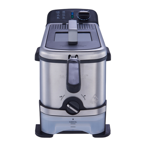
Although the Turbofry 2<XX>is a continuous filtering
machinetheMain Filter Bagswill needto bechangedon
a daily basis(Depending on usage.)The vacuum gauge
is graduatedsothat it will show the condition of the Fil-
ter Bags.When the Filter Bags are new the needle will
readin the GREEN zone, asthe Filter Bagsfill up with
debris theneedlewill rise. The YELLOW zone is an in-
dication that the Filter Bags are filling and that it thc
time to change the Filter Bags is getting close. If thc
Turbofry 2<XX>is in use (the middle of Supper for cx-
ample) when the needle moves to the top of the YEL-
LOW zoneit is permissibletowait until thesoonestavail-
able time until changing the Filter Bags. If the needle
risesinto theBLUE zoneit is time to changeor clean the
Filter Bags.
NOTICE -It is important that the operatorsbecomefa-
miliar with the fryer and the times at which it will need
filtering. This will alleviate the need to shut the fryer
down andfilter during acritical cooking period.
Follow thestepsoutlined below to completethe filtering
process:
(The numbersreferencedbelow refer to the Component
Recognition drawing on page#6.)
1. Using thesupplied Filter Bag RemovalTool, remove
the Filter Bag Guard andplace in anareawhere the
oil candrain.
2. With themachine running brush the areaaround the
Filters to stir up any debris to be collected by the
Filter Bags.
3. Turn themachine off by pressingthe(ill] key on the
Digital Control (#15). (Press the ON/OFFrrEST
Switch for Computer controlled machines.)
4. Openthe GreenDrain Valve Handle (#9) by turning
clockwise until it is in the vertical position. The oil
will now drain into the lower pan (#14).
5. Turn the pump on by pressing the Pump Override
Switch (#3). The Filter Pump will start and the oil
will be pumped from the Filter Bags.
6. After approximately 1-3minutes or when the oil has
stoppedcorning out of the Oil Circulation Tube the
Oil will havebeenpumpedfrom theFilter Bags,turn
the pump off with the Pump Override Switch (#3).
The pump will stop running.
7. It is recommendedthat the Sump ScreenAssembly
(#12) becheckeddaily. Pull the Cover (#13) out and
awayfrom the Sump ScreenAssembly (#12). Allow
the oil to drain fully.
8. Turn the Sump Screen Assembly (#12) counter
clockwise until it becomesfree from its housing.
9. Pull the Sump ScreenAssembly (#12) out slightly
and allow any excessoil to drain into the lower pan.
Inspect the screenfor debris. If any debris is found
shakethe Sump ScreenAssembly until it is clean.
WARNING
Since Water will instantly boil when it is introduced
into cooking temperature oil it is very important that
ALL pans be completely DRY before reassembly.
10. To install the Sump Screen Assembly feed the as-
sembly into the hole and turn clockwise until the
threads seat.Close the Cover.
11. Using the supplied Filter Bag Removal Tool remove
a Filter Bag Retainer along with its Filter Bag. The
Filter Bag will be 1/3to 1/2 full of debris. (Follow
the recommendations outlined at the beginning of
the section regarding the reuse of the Filter Bags.)
Lift the Filter Bag from the Retainer and discard.
The Filter Bag Retainercannow be washedwith hot
water. Repeatthis processfor the secondFilter Bag.
12. Install the new Filter Bagby hanging it on the Filter
Bag Retainer. Feedthebottom of the Filter Bag into
the housing using the Clean Out Rod to make sure
the bottom of the Filter Bag rests in the bottom of
the housing.
Notice -It is important thattheFilter Bagsarelocatedin
thebottom of thehousingandareNOT bunchedup. Also
that the top of the Filter Bag where it hangson the Re-
tainer should, once installed, protrude slightly over the
top of the Filter Bag Retainer.
13. Repeat step#12 for the secondFilter Bag.
14. Close the Green Drain Valve handle (#9).
15. Replace the Filter Bag Cover over the Filter Bag
Housing.
16. Pull the PumpInlet SelectorKnob (#17) OUTWARD
so that the filter pump will suction from the Lower
Pan (#14).
17. Pressthe Pump Override Switch (#3), the pump will
start and the oil will return to the fry tank. When the
Filter Pan (#14) is empty turn the Pump Override
switch OFF.
Notice. This would be the ideal opportunity to usethe
Flush Hose. Follow the instructions outlined in the next
section for the useof the Flush Hose.
FlushHoseSelectorKnob INWARD.
18.Pressthe
12

19.DisconnecttheFilterPickUpAssembly(#10)from
thePumpSuctionConnection(#11)bygraspingthe
FilterPickUpAssembly(#10)andpullingtotheleft
asshown.
20. Pull the Filter Pan (#14) out and remove the Filter
Pick Up Assembly (#10) from the pan. Unscrew the
large nut at the end of the Filter Pick Up Assembly
(#10) from the Pick Up Screen.Eachpiecemay now
bewashedwith soapandwateror in thedish washer.
21. When the parts are clean anddry they can bereas-
sembled by screwing the Filter Pick Up Assembly
(#10) onto the Pick Up Screenin a clockwise direc-
tion. Place the assemblyin the bottom of the Filter
Pan (#14) and push the Filter Pan (#14) under the
fryer. Carefully place the Filter Pick Up Assembly
(#10) end into the Pump Suction Connection and
presstogether.
22. Turn the fryer on by pressing the ~ key on the
Digital Control (#15).
Your fryer is now readyto use.
The Turbofry 2(xx) has a Flush Hose feature that will
allow the user to wash down the inside of the fry tank.
The Flush Hosecanalsobeusedfor pumping theoil into
a waste oil container when it is no longer usable.
CAUTION
The Flush Hose can dischargeHOT oil. Use extreme
caution when handling! Never start the pump without
first ensuring that the hose is pointed in a safedirec-
tion.
ConnecttheFlushHosetotheFlushHoseConnec-
tor (#6) by pulling theblackring backonthequick
disconnecLPushthehoseendonto theconnection
I.f.
and release the black ring.
2. Drain the oil from the fry tank into the Lower Pan
(#14) by turning theDrain Valve Handle (#9) clock-
wise into the openposition.
3. Pull the Pump Outlet Selector (#7) into the Flush
Hose position.
4. Pull the Pump Inlet Selector Knob (#17) into the
Lower Panposition.
5. Point the nozzle into the fry tank.
6. Turn the pump ON by pressing the Pump Override
Switch (#3) to the ON position. Use the Flush Hose
for thedesiredpurpose.Turn thepumpOFF bypress-
ing thePump Override Switch (#3) to the OFF posi-
tion.
7. When finisheddirecttheendof theFlushHoseNozzle
into theLower Panto prevent spilling.
CAUnON
The fitting where the flush hose attachesto the fryer
will be very hot after use.Use insulated rubber gloves
and extreme caution whenhandling.
Pull the black ring back on the quick disconnect and
releasethe Flush Hoseconnection. Allow all of the
oil in the Flush Hose to drain into the Lower Pan.
The Flush Hose should now be removed to its stor-
agelocation.
8. Pressthe Pump Outlet Selector (#7) until it stops.
9. Turn theDrain ValveHandle (#9) counter c]ockwise
to close thedrain vaJve.Refill the fry tank by press-
ing the Pump Override Switch (#3) to the ON posi-
tion. When the Lower Pan (#14) is empty turn the
Pump Override switch OFF.
10. Press the Flush Hose Selector Knob INWARD.
Your fryer is now readyto use.
13

In order to keep your new Pitco Frialator Turbofry 2000
operating and looking in top condition it is necessaryto
perfonn a few simple taskson a daily, weekly, monthly
and quarterly basis. Follow the chart below to find the
frequency atwhich thesePreventativeMaintenanceItems
should be performed:
Follow the directions outlined below for the instructions
on how to perform the given task:
DaD! Cleanin&:
It is recommendedthat,in addition to flltering, theexter-
nal components of the fryer be cleaned in the following
manner.
Turn the fryer OFF by pressingthe~ key on theDigi-
tal Control panel. Using a soft clean cloth to wipe the
exterior surfacesuntil they arefree of oil. A smallamount
of non abrasivecleanermay beused on stubbornstains.
Weekl! Cleanine:
At leastonceaweekthefollowing preventativemainte-
nanceproceduresshouldbeperfonned:
CleanFilter BagHousing,
CleanPumpSuctionScreen.
CleanOil CirculationTube,
CleanFry TankusingtheBoil Outprocedure,
Follow theinstructionsbelowfor instructionsoneachof
theseitems:
Filter Bag Housing. After theoil hasbeendrainedfrom
the Filter Bag Housing (Step#12 and 14in the Filtering
Procedure.) Usethe suppliedFilter Bag RemovalTool to
lift the complete Filter Bag Housing out of the machine.
Wash the Filter Bag Housing with soapand water to re-
move all debris. Dry thoroughly and instal1in the ma-
chine. Make surethe Housing is seatedcorrectly before
installing the Filter Bags.
Pump Suction Screen. Follow the instructions outlined
in the Main Filter Bag Changing Procedure, step #s 8
through 11.Useanabrasive,NON metallic, scouring pad
on persistentstains.
on CirculationTube.Grasp the Oil Circulation Tube
Handle (#9, page5) and pull to the right until it is free
from the housing.Lift the Oil Circulation Tube from the
fry tank. The Oil Circulation Tube may be washed with
soap and water. Use a toothpick or similar tool to push
the crumbsanddebris out of thecirculation holes. Thor-
oughly dry theOil Circulation Tubeandreinstall by care-
fully aligning the end in the housing, lower the handle
until it is seatedon thebracket. Pushthe Oil Circulation
Tube into thehousing until it seats.
Vacuum GaU2eInsoection:
Each time that the pump is switched off or the machine
shuts the pump off during a Filter Bags Change, check
the VacuumGauge(#16,page6) to makesurethe needle
points to the zero mark. The Vacuum Gauge will only
point to zero when the pump is NOT rubbing. If it does
not point to the zero or very close call an Authorized
Service Agency to havethe Vacuum Gaugechecked.
Boil Out Procedure:
Periodically it will benecessaryto perfOmtwhat is known
asaBoll Out. This removesbakedon frying oil from the
inner surfacesof the fry tank. This is bestaccomplished
when the oil is ready to be replaced.
Due to the unique design of the TURBOFRY 2<XX>,the
Boll Out procedureismore involved thanthat of aregu-
lar fryer. It is an easyjob if the stepsin the procedure
outlined below are followed. Always use Pitco Fryer
Cleaner to boil out the TURBOFRY 2<XX>.Other clean-
ers not approvedby Pitco may be harmful to materials
used in the cons1ructionof the TURBOFRY 2000. Any
damage done by the use of other cleaners will not be
coveredby thePitco warranty. The Procedurehas3 main
parts - Cleaning, Neutralization and Rinsing.
Checkthatthecontroller is programmed to heat with
ameltcycle,theDigitaldisplaywillshow[:EEJ
(The Computerdisplay will show ~J:1Q]or
~IOOrn.)
Checkthecunent SetTemperaturesettingof thecon-
troller. Reprogramthecontroller to atemperatureset-
Other manuals for TURBOFRY 2000
1
Table of contents
Other Pitco Fryer manuals