manuals.online logo
Brands
  1. Home
  2. •
  3. Brands
  4. •
  5. PITT
  6. •
  7. Cooktop
  8. •
  9. PITT Foessa User manual

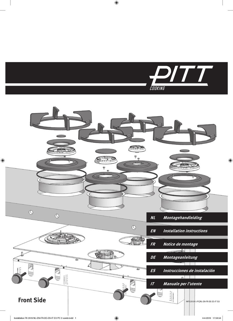
PITT Foessa User manual

Made in Holland
These documents contain instructions to securely and successfully install PITT®cooking into
kitchen benchtops. Furthermore, they indicate which level of craftsmanship is required. To
make a warranty claim, installation procedures should be applied as described. PITT®cooking
is exclusively intended for consumer use.
IH2019-1-PC/AU
Installation and handling PC AU V1 2019.indd 1 6-5-2019 12:34:23
Caution
Do not used the enclosed Aluminium Heat
Conductors as a benchtop template! Only
use the paper template provided.
Benchtop and Cabinetry procedures
and guidelines for PITT®cooking
For more detailed information visit Installation
and handling instructions www.pittcooking.info
1. Benchtop materials suitable for PITT®cooking 3
4
7
4. Installation the kitchen benchtop 9
5. Installation PITT®cooking in the kitchen benchtop 11
Installation and handling PC AU V1 2019.indd 2 6-5-2019 12:34:23
2. Manufacturing hole cut-outs
3. Manufacturing hole cut-outs |Solid Surface
Contents
1a. PITT®cooking can safely be built into:
• Compact board (eg. Trespa)
• Concrete
• Glass
• Natural stone (eg. granite, marble)
Additional requirements apply to Solid Surface. See chapter 3.
1b. The minimum thickness of the core material is 4 mm.
For Solid Surface, Quartz composite, compact board and natural stone applies a minimum
thickness of the core material (solid) of 10 mm.
For Top Side for all materials, a maximum thickness of 35 mm applies.
For Front Side for all materials, a maximum thickness of 25 mm applies.
The bottom of the benchtop needs to be completely flat, in order to bring the
heat conductor in full contact with the benchtop.
1. Benchtop material suitable for PITT
®
cooking
!
!
3
!
Installation and handling PC AU V1 2019.indd 3 6-5-2019 12:34:23
•Stainless steel (eg. 4mm solid or 1(+) mm on substrate board*
*When using astainless steel benchtop with asubstrate asuitable adhesive must be used. The
min specifications for the adhesive is 90 degrees Celsius.
•Solid Surface (eg. Corian, Hi-Macs, Staron)
•Quartz composite (Caesarstone, Silestone, Quantum Quartz, Smartstone)
•Ceramics (eg. Dekton, Neolith, Maximim)
PITT®cooking should never be installed into solid wood or benchtops with an HPL
top layer. (eg. Laminex)
!The guidelines of the kitchen manufacturer and/or the manufacturer of the kitchen
benchtop should always be strictly followed.
2a. The C-size for Top Side models should be at least 50 mm (fig.1).
The distance between the cut out (Top Side and Front Side) and the sides (left or right) of the
benchtop should be at least 150 mm.
Fig. 1
35
4
min. 50
max. 100
min. 650
2b. The C-size for Front Side models should be at all times 75 mm (fig.2)
75 xed
C-size
min. 150
Fig. 2 Fig. 3
Installation and handling PC AU V1 2019.indd 4 6-5-2019 12:34:24
2. Manufacturing hole cut-outs for benchtop’s
Front Side can be applied to the front side of the benchtop as well as the blind of the
kitchen cabinet (whether indented or not). The center of the knobs measured from the top of
the benchtop is at least 50 and at most 100 mm (fig.3).
2c.
Fig. 4 Fig. 5
2d. On the top and bottom of the recess(es) should be a facet of at least 1x1 mm be
applied (with exception for Solid Surface) (fig. 6).
Fig. 6
Facet 1x1 mm
2e.
Fig. 7 Fig. 8
5
Installation and handling PC AU V1 2019.indd 5 6-5-2019 12:34:26
2. Manufacturing hole cut-outs
The insides of the holes should be smooth and even (fig. 4).Irregularities can
cause cracking (fig. 5).
Adhesive connections and/or interconnections should never intersect the holes. These
should have adistance of at least 250 mm to the center of the hole (fig. 7and 8).
Fig. 9
6
Installation and handling PC AU V1 2019.indd 6 6-5-2019 12:34:26
If that horizontal clearance is less than 200 mm, that vertical surface must be protected
by a non-combustible material for 150 mm above the cooktop surface across the entire
length (depth, width).
The minimum clearance from a combustible surface shall be a 200 mm horizontal
distance from the periphery of any gas burner (AS/NZS 5601.1). (fig. 9).
2f.
2. Manufacturing hole cut-outs
!The guidelines of the manufacturer of the Solid Surface material should always be strictly
followed.
In case of Solid Surface the following extra instructions apply:
3a. Use a router or CNC machine to prevent jagged recesses.
Radius R = 3 mm
Fig. 10 Fig. 11
Extra plate Solid Surface
3b. Glue an extra Solid Surface plate at all times at the bottom of the benchtop. This plate
should have the same measurements as the PITT cooking heat conductor, and the same
thickness as the benchtop (fig. 10).
3c. A range of minimum R=3 mm should be applied on the top and bottom of the recess(es). By
sanding it smooth afterwards, possible cracks can be prevented (fig. 11).
7
3d. If the benchtop has been thickened, a ladder frame must always be applied (fig. 12).
Forthecorrectdimensionsoftheladderframe,wereferyoutotheinstructionsofthe
manufacturer of the Solid Surface product.
!We advise to use a ladder frame at all times.
Fig. 12
Installation and handling PC AU V1 2019.indd 7 6-5-2019 12:34:27
3. Manufacturing hole cut-outs |Solid Surface (eg. Corian, Sharon, Hi-Macs)
3e. Apply aluminium tape and thermo tape in the recess(es), in this order:
1) aluminum tape 2) thermo tape 3) aluminum tape (fig. 13).
The aluminum and thermo tape should be overlapping the top of the benchtop surface with at least
5 mm. This seal will offer protection to the changes in temperature.
Aluminum tape
Thermo tape
Aluminum tape
Note!
Tape may not be folded on edge of recess.
Heat conductor
Fig. 13
It is very important that this sealing does not stick out - this because the heat conductor
should be able to connect 100% with the bottom of the benchtop.
!
8
Installation and handling PC AU V1 2019.indd 8 6-5-2019 12:34:27
3. Manufacturing hole cut-outs |Solid Surface (eg. Corian, Sharon, Hi-Macs)
4. Installation the kitchen benchtop
!The guidelines of the kitchen manufacturer and/or the manufacturer of the kitchen benchtop
should always be strictly followed.
4a. The cabinets should be placed perfectly levelled (fig. 14 and 15).
Fig. 14 Fig. 15
9
4b.
Fig. 16
Installation and handling PC AU V1 2019.indd 9 6-5-2019 12:34:28
If there is asubstrate under the benchtop the substrate should be cut to fit the PIT cooktop.
The cutout should be the same size (+10 mm) as the PITT®cooking module. This is to bring
the heat conductor in full contact with the core material (fig. 16).
min. 3 mm
min. 3 mm
4c. The benchtop should have full support on the left, right, front and back side of the PITT
cooking unit (fig. 17). This prevents tension in the benchtop from the weight of the cooking
unit. We advise to support the benchtop with a ladder frame.
4d. The distance between the kitchen benchtop and the wall and/or cabinets should be at least 3
mm (fig. 18). This allows the material to expand.
Fig. 17 Fig. 18
min. 3 mm
4. Installation the kitchen benchtop
10
Installation and handling PC AU V1 2019.indd 10 6-5-2019 12:34:29
5. Installation PITT
®
cooking into benchtop
!Strictly follow the PITT®cooking installation instructions. The installation manual can be
downloaded via www.pittcooking.com/downloads.
5a. The PITT®cooking module should always be fully supported with the PITT®cooking support
set to prevent bending of the kitchen benchtop (fig. 19 and 20).
5b. In case of service, the PITT®cooking module should ALWAYS be able to be disassembled
without disassembling the cabinets and/or kitchen benchtop (fig. 21).
Fig. 21
11
Fig. 16
Support bar
Fig. 19 Fig. 20
89mm TS
134 mm FS
119mm TS
164 mm FS
TS = Top Side
FS = Front Side
Installation and handling PC AU V1 2019.indd 11 6-5-2019 12:34:30

This manual suits for next models

9

Other PITT Cooktop manuals

PITT 4000001 Guide

PITT

PITT 4000001 Guide

PITT Drum User manual

PITT

PITT Drum User manual

PITT Colo User manual

PITT

PITT Colo User manual

Popular Cooktop manuals by other brands
Buffalo GG769 instruction manual

Buffalo

Buffalo GG769 instruction manual

Summit CR2B120 owner's manual

Summit

Summit CR2B120 owner's manual

Electrolux ICON E30IC80ISS Use & care guide

Electrolux

Electrolux ICON E30IC80ISS Use & care guide

IKEA FORNEBO manual

IKEA

IKEA FORNEBO manual

Whirlpool SM988PEP Use & care guide

Whirlpool

Whirlpool SM988PEP Use & care guide

Sharp KB5121KK - 30" Glass Ceramic Cooktop installation manual

Sharp

Sharp KB5121KK - 30" Glass Ceramic Cooktop installation manual

Hallman HGC2401ST Installation and owner's manual

Hallman

Hallman HGC2401ST Installation and owner's manual

Maytag CGC2430AD series technical information

Maytag

Maytag CGC2430AD series technical information

Potterton Gold Combi HE User's guide and important warranty information

Potterton

Potterton Gold Combi HE User's guide and important warranty information

Bauknecht CTAI8740FSIN Instructions for use

Bauknecht

Bauknecht CTAI8740FSIN Instructions for use

KitchenAid KICU509X Use and care guide

KitchenAid

KitchenAid KICU509X Use and care guide

Fisher & Paykel CookSurface CG363ML installation instructions

Fisher & Paykel

Fisher & Paykel CookSurface CG363ML installation instructions

Dacor Renaissance RNTT365GB Planning guide

Dacor

Dacor Renaissance RNTT365GB Planning guide

Frigidaire FGEC3048US user manual

Frigidaire

Frigidaire FGEC3048US user manual

Viking DGRT series installation guide

Viking

Viking DGRT series installation guide

Kitchen Living 45360, 08/14, HD2013B user guide

Kitchen Living

Kitchen Living 45360, 08/14, HD2013B user guide

Nesco Everyday SB-01 Operation manual

Nesco

Nesco Everyday SB-01 Operation manual

AEG A604VTGB-M manual

AEG

AEG A604VTGB-M manual

manuals.online logo
manuals.online logoBrands
  • About & Mission
  • Contact us
  • Privacy Policy
  • Terms and Conditions

Copyright 2025 Manuals.Online. All Rights Reserved.