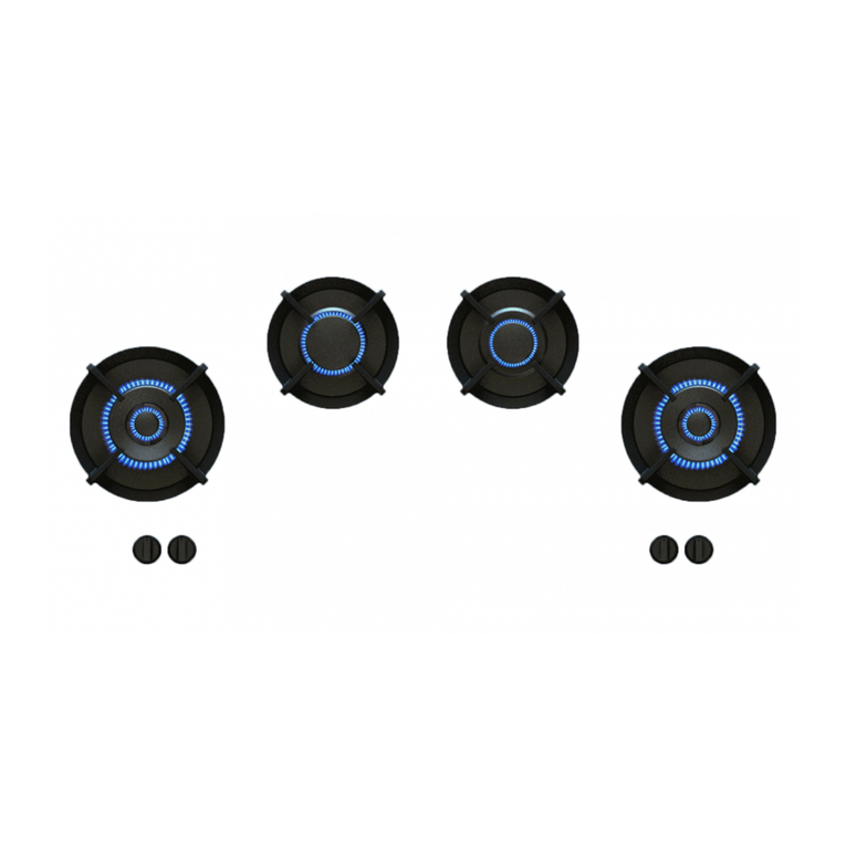
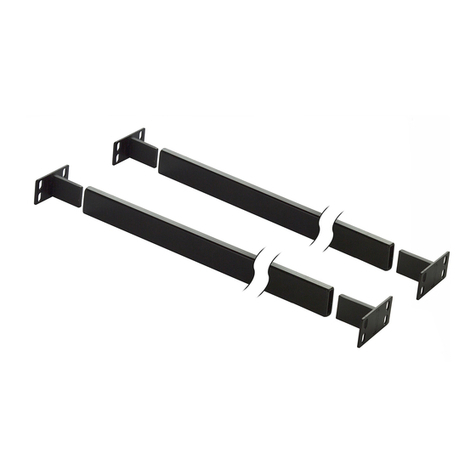
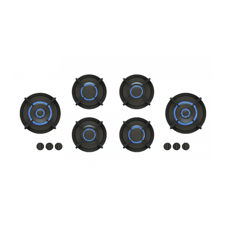
PITT Colo User manual

INFS2019-1-PC/NL-EN-FR-DE-ES-IT EU
Front Side
NL Montagehandleiding
EN Installation instructions
FR Notice de montage
DE Montageanleitung
ES Instrucciones de instalación
IT Manuale per l’utente
Installation FS 2019 NL-EN-FR-DE-ES-IT EU PC 2 combi.indd 1 4-4-2019 17:59:54

Montagehandleiding Front Side
!
Belangrijk!
Bij het niet juist afstellen van de bedieningsknoppen
zullen de branders niet of slecht ontvlammen.
Om de garantie en het goed functioneren van de kookunit
te waarborgen dient de montage, zoals beschreven in
deze handleiding, zorgvuldig uitgevoerd te worden.
NL
7. Plaats de hitteschilden inclusief
afdichtingringen (stap 2) op de branders
en schroef deze vast met bijgeleverde
schroeven.
1. Overzichtsweergave van de verschil-
lende onderdelen.
2. Druk de afdichtingring voorzichtig
over de rand van het hitteschild. Contro-
leer hierbij of de ring in zijn geheel goed
aansluit.
!
3. Overzicht van de stelschroeven (S).
S
5. Plaats de flenzen in de juiste uitspa-
ringen en positioneer de unit voorzichtig
onder het werkblad. Controleer of de
warmtegeleider goed gepositioneerd ligt.
!
6. Controleer of de flenzen gecentreerd
zijn geplaatst in de uitsparingen. Let op:
indien dit niet het geval is functioneren
de flenzen niet goed.
4. Draai alle stelschroeven terug tot circa
3 mm boven de unit. Plaats daarna de
warmtegeleider op de unit.
8. Zorg bij de wokbrander er altijd voor
dat de V-vormige uitsparing in lijn staat
met de as van de brander. Dit hitteschild
wordt met drie schroeven bevestigd.
9. Meet de afstand tussen de voorzijde
van de unit en de voorlijst (of blende).
Deze afstand moet 75 mm bedragen.
75 mm
S
SS
S
S
!
Installation FS 2019 NL-EN-FR-DE-ES-IT EU PC 2 combi.indd 2 4-4-2019 17:59:55

NL
11. Schuif de unit voorzichtig in positie
tot de gaskranen verticaal zijn uitgelijnd
met de uitsparingen in de voorlijst (of
blende).
21. De unit is nu klaar voor gebruik.
10. Let op: de plakstrip onder de afdicht-
schaal van de knop mag nog niet worden
verwijderd.
13. Correct gecentreerde gaskranen.
12. Draai de stelschroeven van achteren
naar voren aan totdat de gaskranen gecen-
treerd zijn met de uitsparingen. Controleer
of alle schroeven zijn aangedraaid.
!
16. Controleer of de knop voldoende
uitsteekt. De knoppen dienen 13-15 mm
boven afdichtingschalen uit te steken.
17. Controleer of de knoppen soepel
draaien en na indrukken terugspringen.
Verwijder zo nodig, voorzichtig het af-
dichtschaaltje en plak deze opnieuw.
18. Sluit de unit aan op gas en elektra en
ontsteek de branders. Als de vlammen
doven na ontsteking dienen de knoppen
opnieuw afgesteld te worden (stap 9).
15. Verwijder de plakstrip van de afdich-
tingschaal. Druk de knop en afdichtings-
schaal als één geheel op de gaskraan,
zodat deze gecentreerd en uitgelijnd zijn.
!
14. Meet ter controle nogmaals de
afstand tussen de voorzijde van de unit
en de voorlijst (of blende). Deze afstand
moet 75mm bedragen.
75 mm
20. Ondersteun de unit met de dubbele
PITT®cooking ondersteuningsset. (zie
bijgevoegde montagehandleiding)
!
13-15mm
19. Controleer of de warmtegeleider
volledig contact maakt met het werkblad.
!
Installation FS 2019 NL-EN-FR-DE-ES-IT EU PC 2 combi.indd 3 4-4-2019 17:59:55

1. Bepaal de maatvoering van de kast en zaag de
ondersteuningsbalken af. LET OP! Juiste lengte balk = Afmeting
binnenzijde kast – 4 mm.
2. Plaats de inzetstukken in de uiteindes van de op maat
gezaagde ondersteuningsbalken.
3. Plaats de ondersteuningsbalk tussen de kast, en positioneer
deze tegen de onderzijde van de PITT®cooking unit. LET OP
DE POSITIONERING, ZIE STAP 4!
4. Positioneer de ondersteuningsbalk zo, dat de stelschroeven,
gasaansluiting en het elektrablok vrij toegankelijk zijn.
*
*
* Minimale afstand van 80 mm
5. Duw de ondersteuningsbalk stevig tegen de onderzijde van
de PITT®cooking unit en draai de onderste twee schroeven
handvast. Herhaal deze stap voor de andere zijde van de kast.
6. Duw de ondersteuningsbalk stevig tegen de onderzijde van
de PITT®cooking unit en draai de bovenste twee schroeven
volledig aan en vervolgens de onderste schroeven volledig aan.
Inhoud van de verpakking:
2x ondersteuningsbalk
Benodigd gereedschap:
• Rolmaat
• Kruiskopschroevendraaier
• Metaalzaag
Montagehandleiding ondersteuningsset
4x inzetstuk
16x kruiskopschroeven 4,2x16 mm
NL
Installation FS 2019 NL-EN-FR-DE-ES-IT EU PC 2 combi.indd 4 4-4-2019 17:59:56

Front Side
EN Installation instructions
Installation FS 2019 NL-EN-FR-DE-ES-IT EU PC 2 combi.indd 5 4-4-2019 17:59:57

Installation instructions Front Side
EN
Important!
When the control knobs are not properly adjusted the
burners will not ignite or burn evenly.
For warranty and the proper functioning of the cooking
unit ensure the mounting is as described in this manual to
the letter.
!
7. Place the heat shields including the
sealing ring (step 2) on the burners and
screw them with the supplied screws.
1. Overview of the various parts. 2. Carefully press the sealing ring over
the edge of the heat shield. Check
whether the ring fits well in its entirety.
!
3. Overview of the set screws (S).
S
5. Place the flanges in the designated
cutouts and position the unit carefully
under the worktop. Check that the heat
conductor is positioned correctly.
!
6. Check that the flanges are centered in
the cutouts. Note: if this is not the case,
the flanges will not function properly.
4. Turn all set screws back to approxi-
mately 3 mm above the unit. Then place
the heat conductor on the unit.
8. Always make sure that the V-shaped
indicator is in line with the shaft of the
burner housing of the wok burner. This
heat shield is attached with three screws.
9. Measure the distance between the
front of the unit and the front frame (or
blende). This distance must be 75mm.
75 mm
S
SS
S
S
!
Installation FS 2019 NL-EN-FR-DE-ES-IT EU PC 2 combi.indd 6 4-4-2019 17:59:58

EN
11. Slide the unit carefully into position
until the gas taps are vertically aligned
with the cutouts in the front frame (or
blende).
21. The unit is now ready for use.
10. Note: the adhesive strip under the
sealing scale of the knob may not yet be
removed.
13. Correct centered gas taps.
12. Tighten the set screws from the back
to the front until the gas taps are centered
with the cutouts. Check that all screws are
tightened.
!
16. Check whether the knobs stick out
sufficiently. The knobs should have a
distance of 13-15 mm above the sealing
scales.
17. Check that the knobs turn smooth-
ly and return to the rest position after
pressing. If necessary, remove the sealing
scale and replace them again.
18. Connect the unit to gas and electricity
and ignite the burners. If the flames go
out after ignition, the knobs have to be
adjusted again (step 9).
15. Remove the adhesive strip from the
sealing scale. Press the knob and the
sealing scale as a one on the gas tap, so
that they are centered and aligned.
!
14. Measure the distance between the
front of the unit and the front frame (or
blende) again. This distance must be 75
mm.
75 mm
20. Support the unit with the double
PITT®cooking support set. (see enclosed
installation instructions)
!
13-15mm
19. Check that the heat conductor makes
full contact with the worktop.
!
Installation FS 2019 NL-EN-FR-DE-ES-IT EU PC 2 combi.indd 7 4-4-2019 17:59:58

EN
1. Determine the dimensions of the cabinet and cut the support
beams with the saw. ATTENTION! Correct length of the beam =
the dimension of cabinet on the inside - 4 mm.
2. Place the inserts into the ends of the beams that have been
cut to size.
3. Place the beams between the cabinet and position it against
the under side of the PITT®cooking unit. ATTENTION: FOR THE
POSITIONING, SEE STEP 4.
4. Position the beams in such a way that the screws, gas
connection and the electricity block are freely accessible.
*
*
* Minimum distance of 80 mm
5. Push the beams firmly against the underside of the PITT®
cooking unit and tighten the lower two screws by hand. Repeat
this step for the other side of the cabinet.
6. Push the beams firmly against the underside of the PITT®
cooking unit and tighten the upper two screws completely.
Then, tighten the lower screws completely.
Contents of package: Tools needed:
• Measuring tape
• Cross-point screwdriver
• Metallic saw
2x support beams
4x inserts
16x cross-point screws 4,2x16 mm
Instructions for installation of support set
Installation FS 2019 NL-EN-FR-DE-ES-IT EU PC 2 combi.indd 8 4-4-2019 17:59:59

Front Side
FR Notice de montage
Installation FS 2019 NL-EN-FR-DE-ES-IT EU PC 2 combi.indd 9 4-4-2019 18:00:00

FR
Notice de montage Front Side
Attention!
En cas de mauvais réglage des boutons de commande les
brûleurs ne s’allumeront pas ou pas bien.
Pour que la garantie et le bon fonctionnement de l’unité
de cuisson soit assuré, il faut que le montage soit
scrupuleusement effectué conformément aux descriptions.
!
7. Placez les écrans thermiques sur
les brûleurs après vissez les écrans
thermiques à la main.
1. Présentation des composants 2. Pressez doucement la bague
d’isolation, attention au bord d’écran
thermique. Vérifiez si la bague couvre
bien l’ensemble.
!
3. Présentations des vis de réglage (S)
S
5. Placez les réflecteurs de chaleur à
l’intérieur des brûleurs. Positionnez
l’unité doucement sur le plan de travail,
assurez-vous que le conducteur de cha-
leur reste en position.
!
6. Assurez-vous que la tête de brûleur est
à l’intérieur de support. Attention: Si la
tête de brûleur n’est pas à l’intérieur de
support brûleur, il ne fonctionnera pas
correctement.
4. Tournez les vis de réglage jusqu’à
environ 3 mm au-dessus de l’unité, par
la suite placez le conducteur de chaleur
sur l’unité.
8. Assurez-vous que pour le brûleur wok,
l’espace en forme de V soit aligné avec
l’axe du brûleur.
9. Mesurez la distance entre le devant
de l’unité et le cadre avant (ou ouver-
ture). Cette distance doit être de 75
mm.
75 mm
S
SS
S
S
!
Installation FS 2019 NL-EN-FR-DE-ES-IT EU PC 2 combi.indd 10 4-4-2019 18:00:01

FR
11. Glissez avec précaution l’unité dans
son emplacement jusqu’à ce que les
injecteurs de gaz soient alignés verticale-
ment avec l’encoche du cadre avant (ou
ouverture).
21. L’unité est prête à l’emploi.
10 Ne pas enlever la bande de protection
pour les prochaines étapes!
13. Injecteurs de gaz correctement cen-
trés
12. Serrer les vis de réglage de l’arrière vers
l’avant jusqu’à ce que les injecteurs de gaz
soient centrés avec les encoches. Vérifiez
que toutes les vis soient bien serrées.
!
16. Vérifiez que le bouton dépasse suf-
fisamment. Les boutons de commande
doivent dépasser d’environ 13 à 15 mm
du bandeau.
17. Verifierz que les boutons ont assez
d’espace pour pousser et tourner, dans
le cas contraire retirez et placez les à
nouveau.
18. Raccordez le tuyau de gaz. Reliez
ensuite le cordon électrique. Vérifiez que
chaque brûleur s’allume bien et reste
allumé (étape 9).
15. Démontez les boutons et les coques
d’obturation, enlevez les bandes adhé-
sives des coques d’obturation.
!
14. Vérifiez à nouveau la distance entre
le devant de l’unité et le cadre avant
(ou ouverture). Cette distance doit être
de 75 mm.
75 mm
20. Renforcez l’unité en fixant les deux
supports PITT®. (voir notice de montage
en annexe)
!
13-15mm
19. Vérifiez que le conducteur thermique
soit entièrement en contact avec le plan
de travail.
!
Installation FS 2019 NL-EN-FR-DE-ES-IT EU PC 2 combi.indd 11 4-4-2019 18:00:01

FR
1. Déterminez les dimensions de l’armoire et sciez les lattes
de soutien. NOTEZ BIEN ! La bonne longueur des lattes =
Dimension de l’intérieur de l’armoire - 4mm.
2. Placez les pièces d’accrochage aux extrémités des lattes de
soutien préablement sciées à la bonne dimension.
3. Placez la latte de soutien entre l’armoire et positionnez-la
contre le dessous de l’appareil de cuisson PITT®. VÉRIFIEZ BIEN
LE POSITIONNEMENT, REPORTEZ-VOUS À L’ÉTAPE 4 !
4. Mettez la barre de soutien de manière à ce que les vis de
réglage, le branchement de la conduite de gaz et le bloc élec-
trique soient facilement accessibles.
*
*
* Distance minimale de 80 mm
5. oussez la latte de soutien fermement contre le dessous de
l’appareil de cuisson PITT®et serrez légèrement les deux vis du
bas. Répétez cette action pour l’autre côté de l’armoire.
6. Poussez la latte de soutien fermement contre le dessous de
l’appareil de cuisson PITT®et serrez entièrement les deux vis
du haut et ensuite serrez entièrement les vis du bas.
Contenu de l’emballage:
2x lattes de soutien
Outils requis :
• Mètre ruban
• Tournevis cruciforme
• Scie à métaux
Instruction de montage du support
4x pièces d’accroche
16x vis à tête cruciforme 4,2 x 16 mm
Installation FS 2019 NL-EN-FR-DE-ES-IT EU PC 2 combi.indd 12 4-4-2019 18:00:02

Front Side
DE Montageanleitung
Installation FS 2019 NL-EN-FR-DE-ES-IT EU PC 2 combi.indd 13 4-4-2019 18:00:03

!
!
S
S
SS
S
S
75 mm
!
DE
8. Die Aussparung in der 5kW Hitze-
schutzabdeckung Richten mit der Rippe
innerhalb des Brenners (n) einsetzen
und mit 3 Schrauben.
7. Die Hitzeschutzabdeckungen mit ihren
Dichtungsringen über den Brenner setzen
und befestigen mit den mitgelieferten
Schrauben.
Montageanleitung Front Side
1. Übersicht der Einzelteile.
Wichtiger Hinweis!
Wenn die Regelknöpfe nicht korrekt eingestellt werden,
lassen sich die Brenner nicht oder schlecht zünden.
Zur Gewährleistung der Garantie und des einwandfreien
Funktionierens der Kocheinheit muss die Montage, wie in
dieser Anleitung beschrieben, sorgfältig ausgeführt werden.
!
2. Den Dichtungsring vorsichtig über den
Rand der Hitzeschutzabdeckung drücken.
Kontrollieren, ob der gesamte Ring
richtig anliegt.
3. Übersicht über die Stellschrauben (S)
5. Die Wärmereflektoren in den Ausspa-
rungen legen und positionier die Einheit
vorsichtig unter der Arbeitsplatte. Sei
sicher, dass der Wärmeleiter in Position
bleibt.
6. Sei sicher das die Flansche in den
Aussparungen konzentrisch sind.
WARNUNG, wenn sie aus der Mitte sind,
werden sie nicht richtig funktionieren.
9. Messen Sie den Abstand zwischen der
Gerätevorderseite und der Frontleiste
(oder Blende). Dieser Abstand muss 75
mm betragen.
4. Alle Stellschrauben senken, bis sie
steigen nur geringfügig über dem Gerät.
Wenn fertig den Wärmeleiter stellen auf
der Oberseite des Gerätes.
Installation FS 2019 NL-EN-FR-DE-ES-IT EU PC 2 combi.indd 14 4-4-2019 18:00:04

!
!75 mm
13-15mm
11. Bringen Sie die Einheit vorsichtig in
Position, bis die Gasregler vertikal mit
den Aussparungen in der Frontleiste (oder
Blende) ausgerichtet sind.
21. Das Gerät ist nun einsatzbereit.
10. Die Schutzfolie nicht trennen von dem
Klebestreifen für die nächsten Schritte! 12. Ziehen Sie die Stellschrauben von
hinten nach vorne an, bis sich die Gasre-
gler im Zentrum der Aussparungen befin-
den. Überprüfen Sie, ob alle Schrauben
angezogen sind.
13. Richitg zentrierte Gasregler 14. Messen Sie zur Kontrolle den Ab-
stand zwischen der Gerätevorderseite
und der Frontleiste (oder Blende). Dieser
Abstand muss 75 mm betragen.
15. Entfern die Schutzfolie von der Dicht-
manschette und drück den Knopf und
Dichtmanschette als Ganzes. Die punkten
ausgerichtet und konzentrisch.
16. Überprüfen Sie, ob der Drehknopf
weit genug herausragt. Die Drehknöpfe
müssen 13-15 mm über die Dichtungs-
schalen herausragen.
17. Überprüf den Knopf (n), wenn sie
genügend Platz zu schieben und drehen
haben. Wenn nicht die Dichtmanschette
entfernen und wieder aufkleben.
!
20. Unterstützen Sie das Gerät mit dem
doppelten PITT®cooking Stützset (siehe
beiliegende Montageanleitung).
18. Schließ das Gerät an zu Gas und strom
und zünd die Brenner. Wenn die Flammen
nach der Zündung löschen überprüf den
Knopf in Schritt 9 wieder.
!
19. Überprüfen Sie, ob der Wärmeleiter
vollständig mit der Arbeitsplatte in Kon-
takt ist.
DE
Installation FS 2019 NL-EN-FR-DE-ES-IT EU PC 2 combi.indd 15 4-4-2019 18:00:04

DE
1. Bestimmen Sie die Abmessungen des Schrankes und sägen
Sie die Stützbalken ab. ACHTUNG! Richtige Balkenlänge = Maß
Schrankinnenseite - 4 mm.
2. Platzieren Sie die Einsatzstücke in die Enden der auf Maß
gesägten Stützbalken.
3. Setzen Sie den Stützbalken in den Schrank ein, und positio-
nieren Sie ihn an der Unterseite des PITT®Kocheinheit. ACHTEN
SIE AUF DIE POSITIONIERUNG, SIEHE SCHRITT 4!
4. Positionieren Sie den Stützbalken so, dass die
Stellschrauben, sowie der Gas- und Stromanschluss frei
zugänglich sind.
*
*
* Mindestabstand von 80 mm
5. Drücken Sie den Stützbalken fest gegen die Unterseite
der PITT®Kocheinheit und ziehen Sie die untersten beiden
Schrauben handfest an. Wiederholen Sie diesen Schritt auf der
anderen Seite des Schrankes.
6. Drücken Sie den Stützbalken fest gegen die Unterseite
der PITT®Kocheinheit und ziehen Sie erst die oberen beiden
Schrauben komplett an und anschließend auch die unteren
Schrauben.
Verpackungsinhalt: Benötigtes Werkzeug:
• Maßband
• Kreuzschlitzschraubenzieher
• Metallsäge
2x Stützbalken
4x Einsatzstücke
16x Kreuzschlitzschrauben 4,2x16 mm
Montageanleitung Stützbalken-Set
Installation FS 2019 NL-EN-FR-DE-ES-IT EU PC 2 combi.indd 16 4-4-2019 18:00:05

Front Side
ES Instrucciones de instalación
Installation FS 2019 NL-EN-FR-DE-ES-IT EU PC 2 combi.indd 17 4-4-2019 18:00:06

!
!
S
S
SS
S
S
75 mm
!
ES
8. Para el quemador de 5kW tienes que alinear
la muesca que tiene el escudo/plato térmico
muesca del quemador con la costilla dentro
del (de los) quemador (es) y asegúrarlo con
los 3 tornillos suministrados.
7. Coloque los escudos/platos térmicos con
su anillos de silicona de sellado fijados sobre
los quemadores y asegúralos utilizando los
tornillos suministrados.
Instrucciones de instalación Front Side
1. Vista general de los componentes del
sistema.
¡Importante!
Cuando los mandos no estén correctamente ajustados, los
fuegos no se encenderán ni quemarán uniformemente.
Para la garantía y un buen correcto funcionamiento del
sistema de cocción, asegúrate de seguir
exactamente
todas las etapas descritas en este manual de instalación.
!
2. Monta suavemente el anillo de sellado
de silicona en el borde del escudo térmico.
Asegúrate que el anillo de silicona está per-
fectamente unido a todo el borde del escudo.
Repita esto para todos los escudos/platos
térmicos.
3. Vista general de los tornillos (S)
5. Instale los reflectores térmicos dentro del
hueco de encastre y coloque suavemente la
unidad debajo de la encimera. Asegúrese de
que el plato conductor de calor permanece en
posición correcta.
6. Asegúrate de que el borde del esqudo/plato
protector, apoye concéntrico con el hueco de
encastre de la encimera.
ADVERTENCIA: si está fuera del centro, el
sistema no funcionará correctamente.
9. Mida la distancia entre la cubierta frontal de
la unidad y el marco frontal (o armadura). Esta
distancia debe ser de 75 mm.
4. Baje todos los tornillos de ajuste hasta que
queden ligeramente por encima de la unidad.
Cuando termine
coloque el plato conductor de calor sobre la
unidad.
Installation FS 2019 NL-EN-FR-DE-ES-IT EU PC 2 combi.indd 18 4-4-2019 18:00:07

!
!75 mm
13-15mm
11. Coloque con cuidado la unidad en la posici-
ón adecuada hasta que los grifos de gas estén
alineados verticalmente con las hendiduras de
fijación en el marco frontal (o armadura).
21. La unidad está lista para ser usada.
10. No despegar la película protectora de la
tira adhesiva del aro del mando que apoyará
en la encimera, antes de continuar con los
siguientes pasos!
12. Atornille los tornillos de fijación desde
atrás hacia adelante hasta que los grifos de
gas estén centrados con las hendiduras de
fijación. Compruebe que todos los tornillos
están apretados.
13. Grifos de gas centrados correctamente. 15. Retira la película protectora de la tira
adhesiva del aro del mando, asegúrate que el
aro y el mando estén alineados y con-céntricos
al hueco de encastre y presiona a la vez mano
y aro asegurándote que se pega a la encimera
correctamente.
16. Compruebe que el botón sobresalga lo
suficiente. Los botones deben sobresalir unos
13 a 15 mm por encima de las placas de
sellado.
17. Compruebe si todas los mandos tienen
suficiente espacio para empujar y girar suave-
mente sobre el aro sellado a la encimera. de
no ser así, con cuidado despega el aro de la
encimera y pégalo de nuevo a la encimera en
su posición correcta.
!
20. Complete la unidad con el set doble de
apoyo de cocción PITT®(ver las instrucciones
de instalación adjuntas).
18. Conecte la unidad a la instalación de gas
y electricidad y enciende todos los fuegos. Si
las llamas se apagasen después del encendido,
comprobar de nuevo la altura de los mandos
(paso 9).
!
19. Verifique que el conductor de calor haga
contacto totalmente con el mostrador de
cocina.
ES
14. Para efectos de control, mida nuevamente
la distancia entre la cubierta frontal de la
unidad y el marco frontal (o armadura). Esta
distancia debe ser de 75 mm.
Installation FS 2019 NL-EN-FR-DE-ES-IT EU PC 2 combi.indd 19 4-4-2019 18:00:07

ES
1. Determine las dimensiones del armario y corte las barras
de soporte. ATENCIÓN: Longitud correcta de la barra =
Dimensiones del interior del armario - 4 mm.
2. Coloque las piezas complementarias en los extremos de las
barras de soporte cortadas a medida.
3. Ponga la barra de soporte en medio del armario y colóquela
contra la parte inferior de la unidad PITT® cooking. ¡ATENCIÓN
AL POSICIONAMIENTO, VEA PASO 4!
4. Coloque la barra de soporte de forma que los tornillos de
ajuste, la conexión de gas y el bloque eléctrico sean de libre
acceso.
*
*
* Distancia mínima de 80 mm
5. Empuje la barra de soporte firmemente contra la parte inferi-
or de la unidad PITT®cooking y apriete a mano los dos tornil-
los inferiores. Repita este paso en el otro lado del armario.
6. Empuje la barra de soporte firmemente contra la parte inferi-
or de la unidad PITT®cooking y apriete completamente los dos
tornillos superiores y luego los tornillos inferiores.
Contenido del paquete:
2 barras de soporte
Herramientas necesarias:
• Cinta métrica extensible
• Destornillador de estrella
• Sierra para metales
Kit de soporte - Instrucciones de montaje
4 complementos
16 tornillos de estrella 4,2x16 mm
Installation FS 2019 NL-EN-FR-DE-ES-IT EU PC 2 combi.indd 20 4-4-2019 18:00:08
This manual suits for next models
4
Table of contents
Languages:
Other PITT Cooktop manuals
Popular Cooktop manuals by other brands
CASO DESIGN
CASO DESIGN Pro Menu 1800 instruction manual

SIMPA
SIMPA SRTH2 operating instructions

FALMEC
FALMEC Zero Instruction booklet

Miele
Miele KM 3034-1 Operating and installation instructions

Fisher & Paykel
Fisher & Paykel CI302DTB installation guide

Omega
Omega OG63XA Installation and operating instructions