Smoke detectors and alarm system control panels have
specifications for allowable loop resistance. Consult the
control panel manufacturer’s specifications for the total
loop resistance allowed for the particular model control
panel being used before wiring the detector loop.
Wiring Instructions
The DH100ACDC detectors are designed for easy wiring.
The housing provides a terminal strip with clamping
plates. Wiring connections are made by stripping about
3/8-inch of insulation from the end of the wire, sliding
the bare end under the plate, and tightening the clamp-
ing plate screw.
[5.7] Perform Detector Check
1. Perform STANDBY AND TROUBLE TEST per Section
[6.2.1].
2. Perform MAGNET TEST per Section [6.2.2.1]. The
RTS451 test of Section [6.2.2.2] may substitute for this
requirement.
3. Perform AIR FLOW TEST per Section [6.1.1].
4. Perform SMOKE RESPONSE TEST per Section [6.1.2].
5. Perform SENSITIVITY TEST per Section [6.2.3].
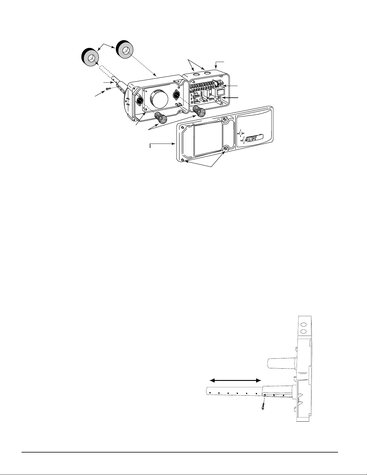
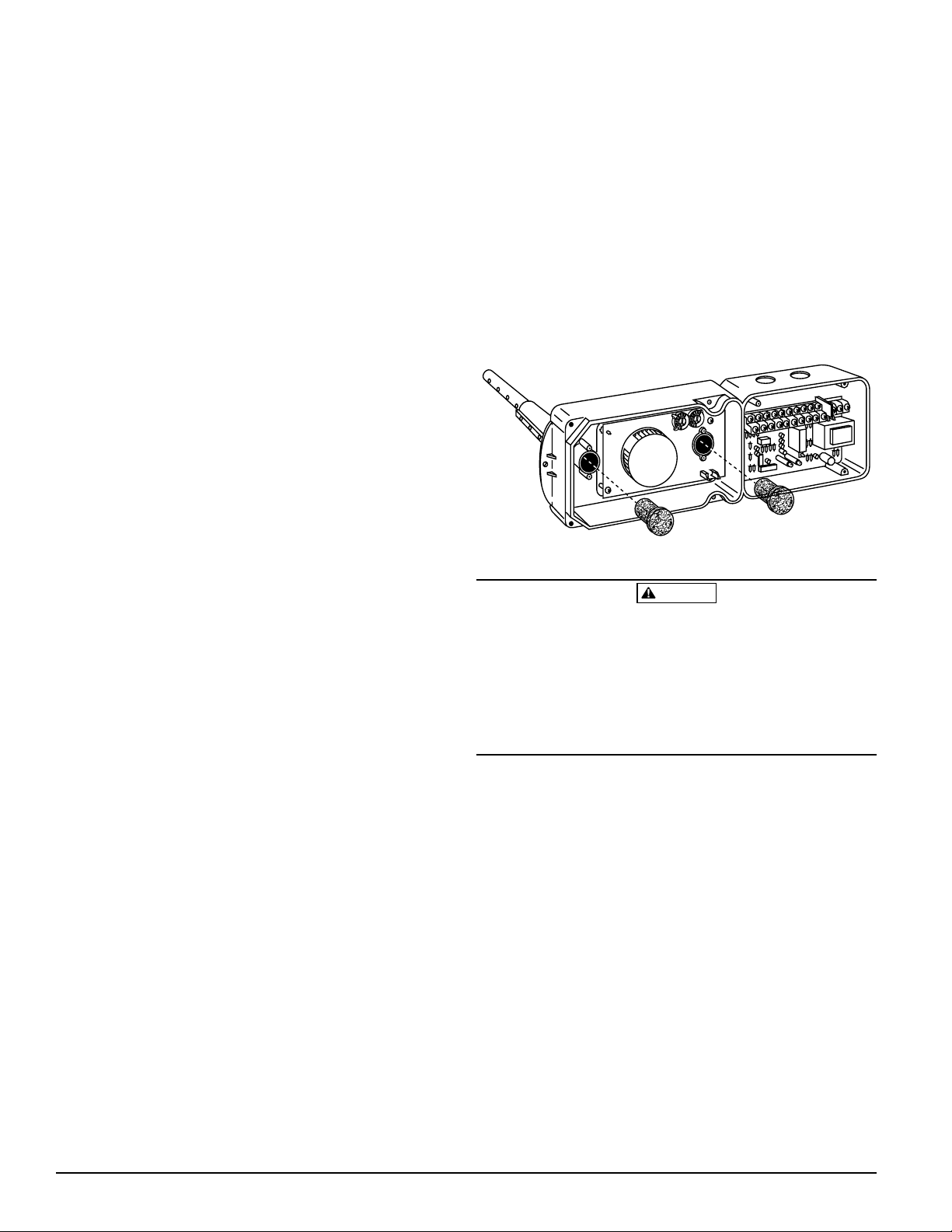
[5.8] Install The Cover
Install the cover using the four screws that are captured in
the housing cover. Be certain filters are installed as speci-
fied in Section [5.5]. Make sure that the cover fits into the
base groove and that all gaskets are in their proper posi-
tions. Tighten the four screws.
[6] Duct Smoke Detector Maintenance And Test
Procedures
Test and maintain duct smoke detectors as recommended
in NFPA 72. The tests contained in this manual were de-
vised to assist maintenance personnel in verification of
proper detector operation.
Before conducting these tests, notify the proper authorities
that the smoke detection system will be temporarily out of
service. Disable the zone or system under test to prevent
unwanted alarms.
[6.1] Smoke Entry Tests
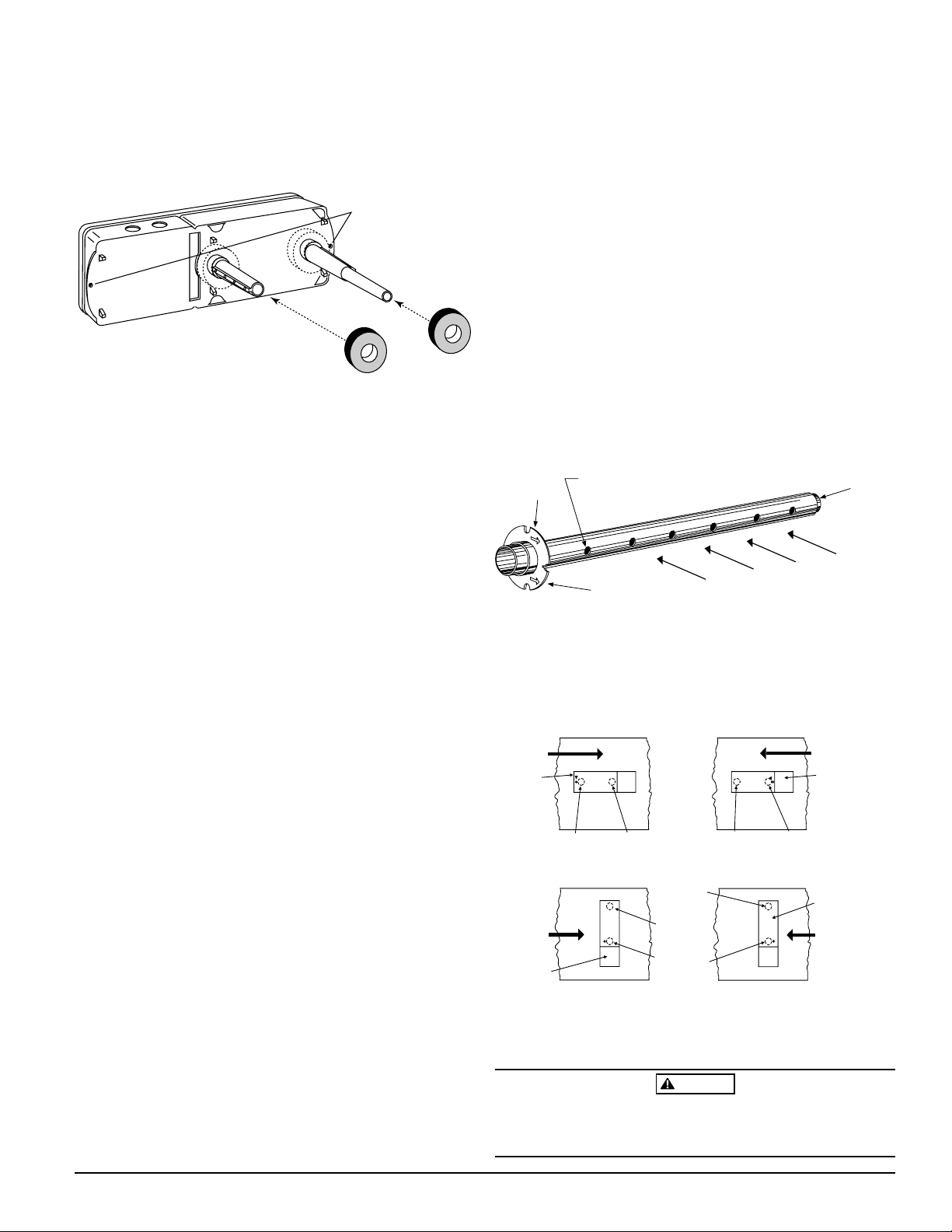
[6.1.1] Air Flow
To verify sufficient sampling of ducted air, use a manometer
to measure the differential pressure created from air flow
across the sampling tubes. The pressure should measure no
less than 0.03 inches of water and no greater than 1.4 inches
of water. The air handler must be operating for this test.
[6.1.2] Smoke Response
To determine if smoke is capable of entering the sensing
chamber, visually identify any obstructions. Plug the ex-
haust and inlet tube holes to prevent ducted air from carry-
ing smoke away from the detector head, then blow smoke
such as cigarette, cotton wick, or punk directly at the head
to cause an alarm. REMEMBER TO REMOVE THE PLUGS
AFTER THIS TEST, OR THE DETECTOR WILL NOT FUNC-
TION PROPERLY.
[6.1.3] Filter Replacement
The filters do not substantially affect smoke performance
even when up to 90% of the filter is clogged. Quarterly vi-
sual inspection usually suffices to determine whether the
filters should be replaced because only a high percentage of
contamination affects performance. If further testing is re-
quired, compare differential pressure readings with and
without the filters installed. If the difference exceeds 10%
replace the filters. In no case should the pressure differen-
tial fall below 0.03 inches of water.
[6.2] Standby, Alarm, And Sensitivity Tests
[6.2.1] Standby And Trouble
Standby — Look for the presence of the flashing green
LED through the transparent housing cover.
The LED should flash approximately every 10
seconds.
Trouble — If the detector LED does not flash, then the de-
tector lacks power (check wiring, panel, or
power supply), the detector board is missing
(replace), the cover has been missing or not se-
cured properly for more than 20 minutes (se
cure cover properly), or the unit is defective
(return for repair).
Test — The trouble condition can be caused intention
ally to verify correct operation of the system.
Remove the detector board to cause a trouble
condition locally and at the system control
panel.
Cover
Tamper — If the cover is removed or not properly secured
for a period longer than 20 minutes, a trouble
signal is generated to indicate the cover is missing.
[6.2.2] Alarm Tests
[6.2.2.1] M02-04-00 Magnet Test
1. Place the painted surface of the magnet onto the TEST
locator on the bottom of the housing (Figure 13).
2. The red alarm LED on the detector should latch on, as
should any accessories (i.e. RA400Z, RTS451). Verify
system control panel alarm status and control panel ex-
ecution of all intended auxiliary functions (i.e. fan shut-
down, damper control, etc.).
3. The detector must be reset by system control panel, front
cover reset button, or remote accessory.
D100-68-00 5 I56-1147-08
Technical Manuals Online! - http://www.tech-man.com