PJ Tech SMARTLIGHT 05 MK3 Installation and operation manual

PJ Tech
Reg. No: CK94/30139/23
V.A.T. No: 4240179202
Cap Lamps
Northlands Business Park
New Market Rd., Northriding
Johannesburg
Republic of South Africa
Tel.: +27 (011) 704-7088 / 9
Fax: +27 (011) 704-7019
e-mail: lamps@pjtech.co.za
www: www.pjtech.co.za
P.O. Box 928
Honeydew, 2040
Johannesburg
Republic of South Africa
Revision A
Operating&Maintenance Manual SM-
05 Mk3 Page 1 of 12
CAP LAMP
SMARTLIGHT 05 MK3
OPERATING
&
MAINTENANCE INSTRUCTIONS
MANUAL

Cap Lamp - SMARTLIGHT 05 Mk3
Operating & Maintenance Manual
CONTENTS
Revision A
Operating&Maintenance Manual SM-
05 Mk3 Page 2 of 12
CONTENTS
1
DESIGNATION................................................................................................................................3
2
TECHNICAL SPECIFICATIONS..................................................................................................3
3
CAP LAMP CONSTRUCTION......................................................................................................4
3.1
Battery Casing....................................................................................................................4
3.2
Head Lamp.........................................................................................................................5
3.3
Cable...................................................................................................................................5
4
CAP LAMP OPERATION...............................................................................................................6
4.1
Operation............................................................................................................................6
4.1.1
Control of Operation..........................................................................................6
4.1.2
Functioning of the Cable Continuity & Voltage Monitoring.........................6
4.1.3
Monitoring Battery Capacity............................................................................7
4.2
Battery Charging...............................................................................................................7
4.2.1
Battery Chargers................................................................................................7
4.2.2
Initial Battery Charge........................................................................................8
4.2.3
Standard Charging Modes ................................................................................8
4.2.3.1
Standard Battery Charge..................................................................8
4.2.3.2
Discharging + Charging (Calibration Mode)..................................8
5
DATA TRANSMISSION .................................................................................................................9
6
REPAIR AND SERVICE.................................................................................................................9
6.1
Periodic Inspection............................................................................................................9
6.2
Annual Inspection..............................................................................................................9
6.3
Random Checks.................................................................................................................9
7
WASTE DISPOSAL.......................................................................................................................10
8
WARRANTY...................................................................................................................................10
9
DELIVERY......................................................................................................................................10
10
STORAGE.......................................................................................................................................10
11
SPARE PARTS ...............................................................................................................................11
12
HOW TO ORDER..........................................................................................................................12

Cap Lamp - SMARTLIGHT 05 Mk3
Operating & Maintenance Manual
DESIGNATION &
TECHNICAL
SPECIFICATIONS
Revision A
Operating&Maintenance Manual SM-
05 Mk3 Page 3 of 12
1DESIGNATION
The SMARTLIGHT-05/M1 cap lamp is designed for individual illumination of workplace. The
lamp’s body is IP65 rated and the internal design conforms to ia standard. The lamp can be used in
the mines and places contaminated with methane at any concentration. Cap lamp uses the NiMH
service-free battery to ensure good illumination in different work conditions. As options it can be
equipped with:
•RFID transponder to monitor movements of the personnel
•methane meter to monitor methane levels
2TECHNICAL SPECIFICATIONS
Description Data
Rated voltage of battery 3,6 V
Battery 3 x NiMH 9,5 Ah
Battery life 1000 cycles - GUARANTEED
Source of light: Main light MLED diode LED 1W
Additional light ALED diode LED 0,07W x 3
Emergency light ELED diode LED 0,07W
Light source life 100,000 hrs
Battery utilisation from full charge MLED only at 100% 30 hours
Example of battery utilization in
sequence (from full charge of
battery)
MLED at 100% 10 hours than
MLED at 20% 85 hours (80% battery
capacity depleted) than
ALED or ELED 31 hours or 95 hours
Battery maximum charging period 12 hours (from completely discharged)
Light intensity at 1m from the lamp +- 3000 lux (after 8 hours of 100% usage)
Light beam angle 120 deg
Ingress protection IP 65
Level of protection explosion-proof I M1 Ex ia I; Certification No: FTZU04ATEX0299
Dimensions 140 x 130 x 48 mm
Head diameter 72 mm
Cable length 1500 mm
Working temperature 0
0
...+ 40
0
C
Weight 1,3 kg
Table No.:1- Technical Specifications
"CE" marking is a declaration from the manufacturer that their product conforms to a specific
Directive(s) adopted by the EEA (European Economic Area) and is a requirement for the
product to be sold into any of the countries in this 18 member group. CE is an abbreviation for
the French phrase Conformité Européene, meaning European Conformance. Unlike hazardous
location approvals, the manufacturers are solely responsible for ensuring their product's
conformance to these Directives which were developed using IEC and Cenelec standards.
These are some of the recognized European approval agencies that have certified Viatran
transmitters to Cenelec (European Committee for Electrotechnical Standardization) and/or
IEC (International Electrotechnical Commission) standards for hazardous locations. Cenelec
attempts to harmonize the electrical standards of its member countries. Generally, IEC
standards are used. However, in certain instances where IEC standards are considered too
vague, Cenelec defines more precise requirements.

Cap Lamp - SMARTLIGHT 05 Mk3
Operating & Maintenance Manual
CAP LAMP
CONSTRUCTION
Revision A
Operating&Maintenance Manual SM-
05 Mk3 Page 4 of 12
3CAP LAMP CONSTRUCTION
Cap lamp consists of the following:
•Battery Casing.
•Head Lamp.
•Cable (links the Battery Casing with the Head Lamp).
3.1 Battery Casing
The Battery Casing consists of the following:
•Enclosure that is made of a robust plastic. At the bottom of the enclosure there are three
contacts that are used to charge the battery and transmit data to the cap lamp and back.
•NiMH Battery Set that supplies electrical power to the cap lamp. After inserting the cap lamp
into a charger, the battery is charged through contacts at the bottom of the enclosure. The
working and charging cycles of the battery are controlled by microprocessor.
•Plate containing a pressure relief micro-valve, separating the battery from the PC board. The
micro-valve releases the air from the enclosure and it opens if the enclosure’s inside pressure
exceeds 0.3bar .
•Electronic Board – Ref.. page 10 - that contains a microprocessor as well as other electronic
components. The electronic board controls the operation of the cap lamp. The electronic
board is equipped with the following:
-Plug-in Socket to connect the casing cover (Figure 1-3) to the battery set (Figure 1-
1). Programmer unit can also be connected via the plug-in socket.
-Terminal Strip to connect a cable (Figure 1-5) linking the battery set (Figure 1-1) to
the head lamp (Figure 1-6). The electronic board is encapsulated in the casing cover
with a polyurethane filling.
•Battery Casing Cover – Ref. page 10 - (Figure 1-3) is made of a high impact resistant plastic.
The cover is mounted to the enclosure with two six lobe bolts. A special rubber seal (Figure
1-4) ensures tight fit. An emergency ELED diode is encapsulated in the cover. The cover
(Figure 1-3) has a cable inlet for the cable that connects the battery set (Figure 1-1) to the
head lamp (Figure 1-6). The lamp’s membrane switch (Figure 1-10) is located on the
opposite site on the top of the cover. The cover (Figure 1-3) is connected to the electronic
board by means of a cable with a connector pin. In case of a cable (Figure 1-5) breakage
between the head lamp and the battery, the ELED emergency diode mounted in the cover of
the battery casing (Figure 1-3) starts to emit continuous light. The ELED diode light protects
the users from a complete loss of light.
The battery casing can be fitted to a hip belt by means of a stainless steel wire belt bracket
(Figure 1-2) that is fitted to the battery casing.

Cap Lamp - SMARTLIGHT 05 Mk3
Operating & Maintenance Manual
CAP LAMP
CONSTRUCTION
Revision A
Operating&Maintenance Manual SM-
05 Mk3 Page 5 of 12
3.2 Head Lamp
The head lamp consists of the following:
•Lamp Body (Figure 1-6).
•Lamp Treaded Cover (Figure 1-7).
•Lamp Clip (Figure 1-12).
•Protective Glass (Figure 1-9) with a Seal (Figure 1-8).
•Reflector Set (Figure 1-11).
•Cable Inlet.
The body and threaded cover are made of plastic. The head is equipped with a metal lamp clip that
allows clipping it on a helmet. On the side of the lamp body there is a cable entry that connects the
lamp with the battery set. The body is enclosed by means of the threaded cover with the protective
glass. The threaded cover’s tightness and possibility of unscrewing is ensured by means of the seal
and locking screw. The reflector set is mounted inside the threaded cover. The MLED and ALED are
embedded in the reflector and to replace a light source the whole assembly must be replaced. The
lamp clip (Figure 1-12) allows a change of the angle of the light beam relative to miners cap.
3.3 Cable
The cap lamp battery casing is connected the head lamp with a four core cable (Figure 1-5). The
cable is 1,5m long. The cable is characterized by the following:
•High durability.
•Flexibility.
•Resistance to humidity and hydraulic oil.
•Non-flammable.
The cable can be fixed to the miners cap.

Cap Lamp - SMARTLIGHT 05 Mk3
Operating & Maintenance Manual
CAP LAMP
OPERATION
Revision A
Operating&Maintenance Manual SM-
05 Mk3 Page 6 of 12
4CAP LAMP OPERATION
4.1 Operation
4.1.1 Control of Operation
Each time the membrane switch (Figure 1-10) is pressed for about 1 sec it changes sequentially mode
of operation as follows:
•The MLED switches on at 100% power
•The MLED dims to 20% power
•The MLED switches off, ALED switches on
•The ALED switches off, ELED switches on
Next time the membrane switch is pressed the cycle starts again. If the membrane switch is pressed
for longer than 2 seconds all diodes switch off. To switch the lamp on the membrane switch (Figure
1-10) must be pressed again. If the membrane switch is pressed for longer than 10 seconds (the
MLED will signal it by a single flash) the lamp becomes ready for the battery capacity measuring
procedure. The lamp exits this mode after 30 seconds if it is not placed in the charger or after the next
press of the membrane switch. Once the lamp is inserted into the charger within 30 seconds from
entering capacity measuring mode an internal flag is activated and it is only deactivated once the
battery is fully charged. If removed before the charge cycle is completed the charge indicator of the
charger will indicate that the capacity test was interrupted.
IMPORTANT NOTES!
•During charging mode the membrane switch’s functions are disabled.
•The light intensity and functions of each 1 second presses can be factory programmed
to suit Client’s requirements.
4.1.2 Functioning of the Cable Continuity & Voltage Monitoring
Microcontroller controls the connection continuity. In case of cable (Figure 1-5) breakage, the
Emergency ELED switches on. The ELED is located in the cover of the battery casing.
In addition to the monitoring of the cable’s continuity, the battery voltage is also monitored.
Depending on the voltage values, and cable condition the microprocessor indicates with the flashing
ELED as follows:
Cable condition ELED
Ubat≥3.0V UBat<3.0V
OK Flashing Off
Break or Short-
circuit Continuous light Off
Table No.:2 – ELED Reaction Related to the Conditions of the Cable, and Battery Voltage

Cap Lamp - SMARTLIGHT 05 Mk3
Operating & Maintenance Manual
CAP LAMP
OPERATION
Revision A
Operating&Maintenance Manual SM-
05 Mk3 Page 7 of 12
4.1.3 Monitoring Battery Capacity
After the lamp is switched on for the first time so is the microcontroller. At that time the
microprocessor does not have any information about the state of the charge of the battery. The
process of battery’s initial discharge is based on the voltage measurement.
After the battery is discharged and subsequently fully charged all control of the charge level is
maintained by the microcontroller which measures the flow of the electric charge from and to the
battery. In parallel with the charge flow measurement the microcontroller monitors the time the
diodes are switched on. During working cycle (lamp usage) from fully charged, the minimum time
the MLED must be able to emit light at 100% intensity is 10 hours. After that time the base factor
determining the functioning of the lamp is the amount of consumed charge. Once the total consumed
charge reaches 9Ah the normal operation of the lamp is disabled. During this period ALED can be
switched on for a period of 3 seconds at the time. During the lamp usage, in parallel with the used
charge measurement the battery voltage is measured. Once the voltage drops below 3V then
irrespective of the time the MLED is switched on or the amount of consumed charge the whole
operation of the lamp is EMERGENCY DISABLED.
During lamp usage the microcontroller indicates the following levels of discharge:
•80% discharge of the capacity dedicated to the lamp - MLED flashes 6 times
•99% discharge of the capacity dedicated to the lamp – MLED flashes 3 times
Actual level of battery’s remaining capacity is constantly indicated by the ELED flashing as follows:
•81-100% capacity remaining – ELED flashes 5 times
•61 -80% capacity remaining – ELED flashes 4 times
•41-60% capacity remaining – ELED flashes 3 times
•21-40% capacity remaining – ELED flashes 2 times
•0-20% capacity remaining – ELED flashes 1 time
The ELED flashes in the following pattern: 200ms – flash, 300ms pause, 2.5s pause between the
cycles.
4.2 Battery Charging
4.2.1 Battery Chargers
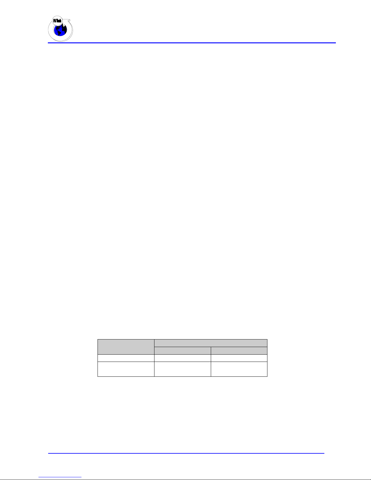
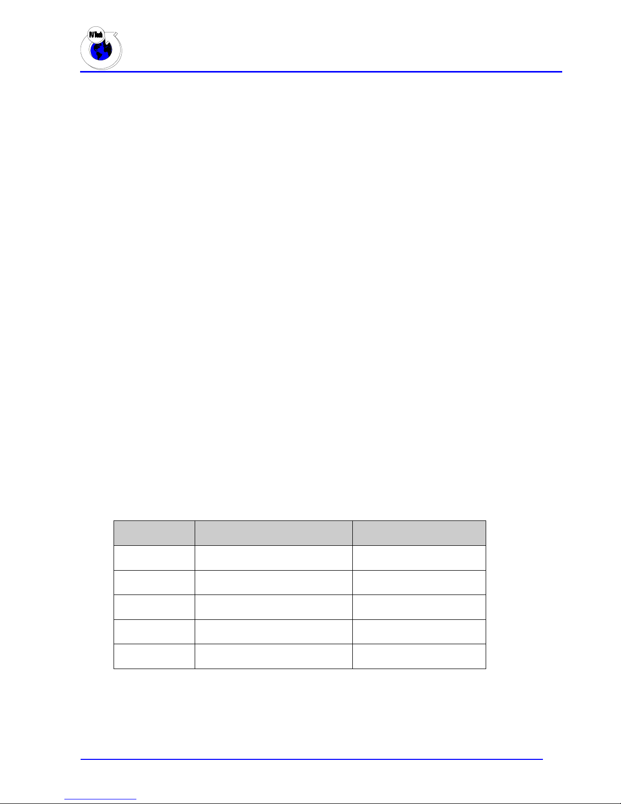
The SMARTLIGHT-05/M1 cap lamps to be charged only in the following charging devices:
Charger Lamp
Capacity Charger
Type Part Number
1
Charger module only
(any charger type) PCL-SM05-CHRG/MOD
1 Single (desktop)
PCL-SM05-CHRG/1
5 Stand alone
(desktop or bench) PCL-SM05-CHRG/5
17 Row
(part of PCL-SM05-CHRG/102) PCL-SM05-CHRG/17
102 Stand Alone
PCL-SM05-CHRG/102
IMPORTANT NOTE!
All lamps are delivered with discharged and conditioned batteries
To enable initial battery charge the electronic board with microcontroller must be connected to
the battery by means of a connector under the battery casing cover (Figure 1-3)

Cap Lamp - SMARTLIGHT 05 Mk3
Operating & Maintenance Manual
CAP LAMP
OPERATION
Revision A
Operating&Maintenance Manual SM-
05 Mk3 Page 8 of 12
4.2.2 Initial Battery Charge
When a new lamp is placed into the charger or after the electronic board with microprocessor is
disconnected from the battery connector, or after full discharge the lamp enters Initial Charge Mode.
If there is any charge left in the battery the LEDs switch on and the discharge cycle starts. After the
battery is fully discharged LEDs switch off and the charging cycle starts. During this cycle the
microprocessor calibrates the battery. This should not be interrupted until finished.
4.2.3 Standard Charging Modes
There are two battery charging modes:
4.2.3.1 Standard Battery Charge
To enable this function the user must insert the battery into the charger. All the LEDs will switch off
and the microprocessor will calculate the amount of charge which should flow into the battery. The
charging cycle starts and ends once the required amount of charge is supplied to the battery. If the
battery temperature exceeds the allowable level the charging stops and resumes once the temperature
drops.
The battery is fully charged when:
•The battery has received the calculated electric charge, or
•Battery voltage >4.45V.
Once the charging cycle is completed the battery is being trickle charged by 20% of the interrupted
current.
Note: Discharging + charging mode can also be used (4.2.3.2).
4.2.3.2 Discharging + Charging (Calibration Mode)
To enable this function the user must press the membrane switch for approximately 10 seconds (the
MLED will signal will signal it by a single flash). The lamp becomes ready for the battery capacity
measuring procedure. The lamp exits this mode after 30 seconds if it is not placed in the charger or
after the next press of the switch. Once the lamp is put into the charger within 30 seconds from
entering calibration mode an internal flag is activated and it is only deactivated once the battery is
fully charged. The LEDs will switch on to discharge the battery. Once the discharge cycle is
completed the LEDs will switch off and the charging cycle will begin. After the lamp is fully
charged and removed from the charger the MLED switches on.
Note:
Should the charging cycle be interrupted (e.g. battery removed from the charger) MLED will not
switch on after the lamp is removed from the charger. Another attempt to put the battery into the
charger will result with the charging indicator of the charger indicating that the capacity test was
interrupted.
Once the charging cycle is completed the battery is being trickle charged by 20% of the interrupted
current.

Cap Lamp - SMARTLIGHT 05 Mk3
Operating & Maintenance Manual
DATA TRANSMISSION,
REPAIR & SERVICE
Revision A
Operating&Maintenance Manual SM-
05 Mk3 Page 9 of 12
5DATA TRANSMISSION
Data transmission is activated when the battery is being charged. The data is sent from the cap lamp
to the battery charger and can be viewed and analysed via PC software system. Data frames are sent
at intervals of 500 milliseconds. Commands from the PC software system are sent in alternate
fashion. Data frames are of a fixed size but the commands frames vary in size.
6REPAIR AND SERVICE
The cap lamp construction allows for no additional operating activities. The battery consists of dry
cells that are sealed inside the battery casing. The average life time of the NiMH battery is 800
cycles.
IMPORTANT NOTE!
Only authorized and adequately trained personnel can be allowed to perform the inspections
and repairs. Should the cap lamp malfunction in any way, PJ Tech should be informed.
6.1 Periodic Inspection
It is recommended that from time to time the following are inspected (cracks, material deterioration):
•Head lamp.
•Cable.
•Battery casing cover.
•Battery set.
IMPORTANT NOTE!
Should the cable be replaced and the head lamp opened, one should make sure not to allow any
impurities onto the lens of the LEDs.
6.2 Annual Inspection
It is recommended that at least once a year the following are inspected:
•Seal of the battery casing cover.
•Seal of the head lamp.
6.3 Random Checks
To ensure the efficiency of the lamp’s illumination, it is recommended that random checks are
performed. Operation of the push button’s as well as lamp’s illumination to be checked during these
checks.

Cap Lamp - SMARTLIGHT 05 Mk3
Operating & Maintenance Manual
WASTE DISPOSAL,
WARRANTEE,
DELIVERY &
STORAGE
Revision A
Operating&Maintenance Manual SM-
05 Mk3 Page 10 of 12
7WASTE DISPOSAL
Packages and used devices should be disposed of according to the mandatory local Laws of waste
disposal.
8WARRANTY
PJ Tech cap lamps are warranted against defects in workmanship and materials for period of 12
months from date of delivery. This warranty does not cover failures due to misuse, neglect, abuse,
improper handling, alteration, improper maintenance or accident, and PJ Tech shall not be liable for
any direct, indirect, consequential or incidental damages from use, results of use or inability to use
this product. Within the warranty period, the faulty product will be repaired or replaced by PJ Tech
free of charge. Except as mentioned above, no other warranty expressed or implied applies.
9DELIVERY
Cap lamps are delivered with disconnected microprocessor connector under the cover of the battery
casing (Figure 1-3). The cap lamp package consists of the following:
•Complete Cap Lamp.
•Box.
•Operating Instructions Manual.
10 STORAGE
Cap lamps should be stored as follows:
•Humidity below 70%.
•Temperature between 10-30
°
C.
•Away from the source of heat and direct Sunrays.

Cap Lamp - SMARTLIGHT 05 Mk3
Operating & Maintenance Manual
SPARE PARTS
Revision A
Operating&Maintenance Manual SM-
05 Mk3 Page 11 of 12
11 SPARE PARTS
Group NO Description P/N
Battery Casing
1 Battery Set PCL-SM05-ELK-70.468
2 Belt Bracket PCL-SM05-ELK-20.128
3 Casing Cover PCL-SM05-ELK-70.479/3
4 Seal PCL-SM05-ELK-35.166
10 Membrane Switch Non-Replaceable
Cable
5 Complete cable PCL-SM05-ELK-25.492/4
16 Cable PCL-SM05-ELK-25.578
13 Cable entry sleeve PCL-SM05-ELK-35.191
14 Cable entry sleeve PCL-SM05-ELK-35.192
15 Washer PCL-SM05-ELK-10.148
15 Nut M18x1,5 PCL-SM05-ELK-10.147
Head Lamp
6 Head Lamp PCL-SM05-ELK-72.605
7 Threaded Cover PCL-SM05-ELK-19.644
8 Seal PCL-SM05-ELK-35.167
9 Protective Glass PCL-SM05-ELK-34.025
11 Reflector Set PCL-SM05-ELK-70.454
12 Head Lamp Clip PCL-SM05-ELK-15.442
Table No.:4 – Spare Parts List
Figure No.:1 – Spare Parts – SMARTLIGHT-05 CAP LAMP
13
12
6
7
8
9
11
15
14
2
5
16
10
3
4
1

Cap Lamp - SMARTLIGHT 05 Mk3
Operating & Maintenance Manual
HOW TO ORDER
Revision A
Operating&Maintenance Manual SM-
05 Mk3 Page 12 of 12
12 HOW TO ORDER
The orders should be sent to the below:
Company Name : PJ TECH
Registration Number
: CK94/30139/23
V.A.T. Number
: 4240179202
Contact Details : Tel.: +27 (011) 704-7088/9
Fax: +27 (011) 704-7019
e-mail: sales@pjtech.co.za
www: www.pjtech.co.za
Physical Address : Northlands Business Park
North Riding
Johannesburg
Republic of South Africa
When placing orders, please provide the below part number:
PCL-SM-05
Table of contents