PKP DR08-25 User manual

Instruction Manual
DR08-25
Turbine Flow Sensor
PKP Prozessmesstechnik GmbH
Borsigstraße 24
D-65205 Wiesbaden- ordenstadt
Tel.: ++49-(0)6122-7055-0
Fax: ++49-(0)6122-7055-50
Email: info@pkp.de www pkp.de

Table of Contents
Safety Information..................................................................................................................2
Device description..................................................................................................................4
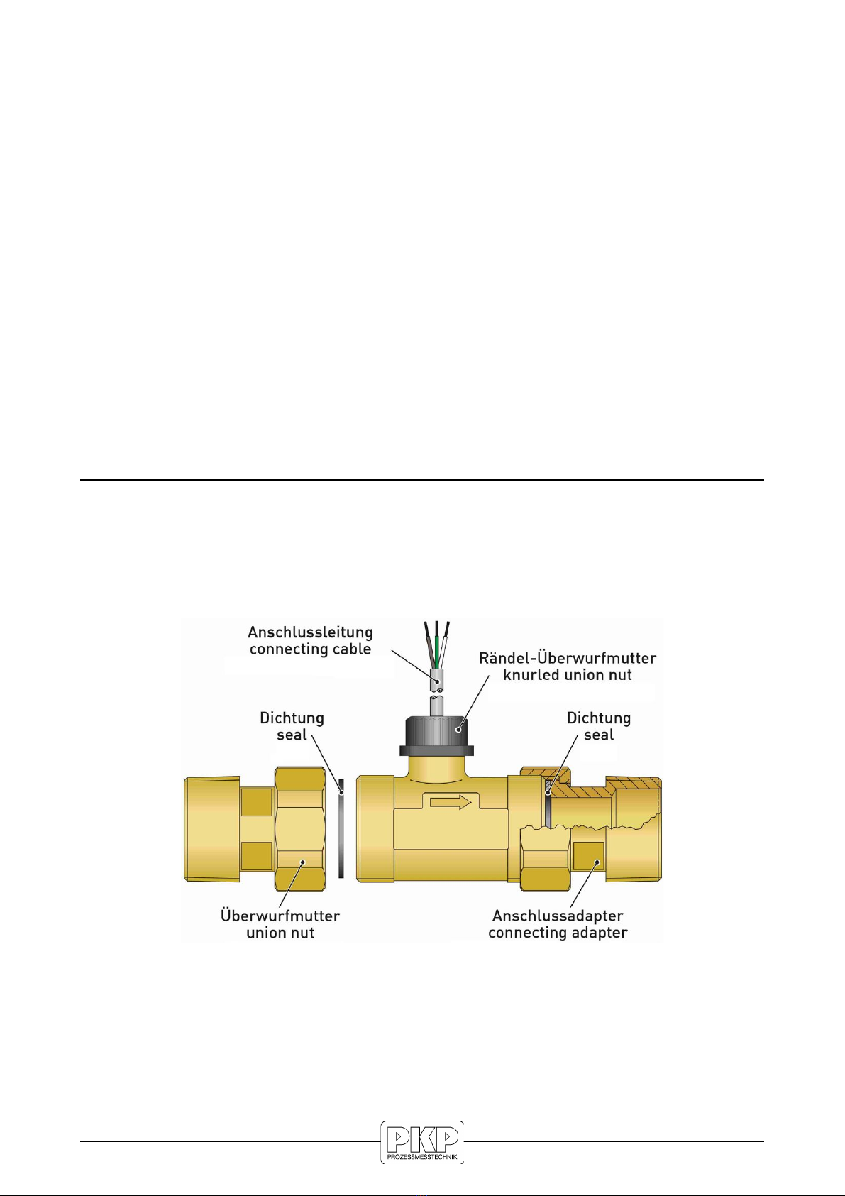
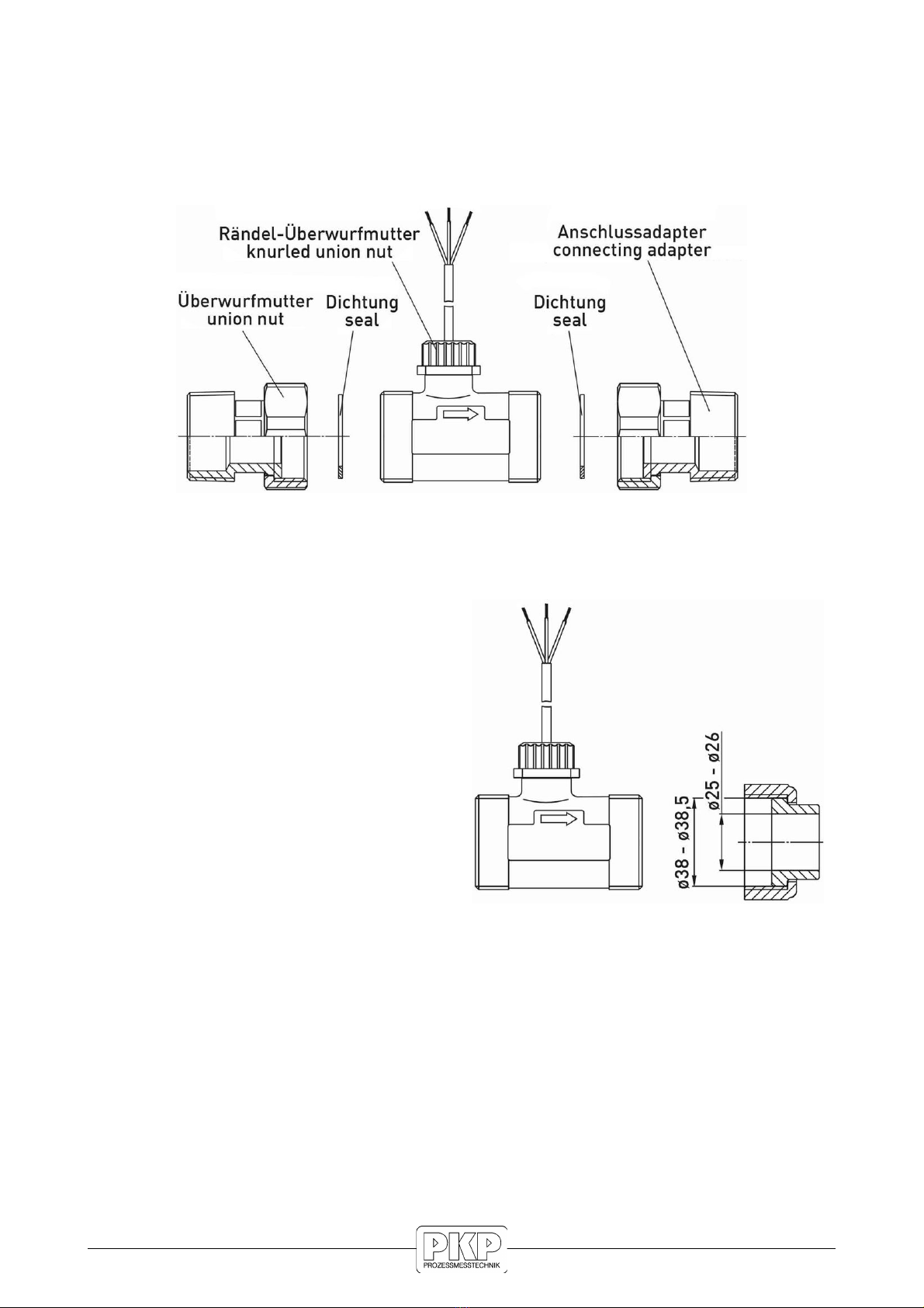
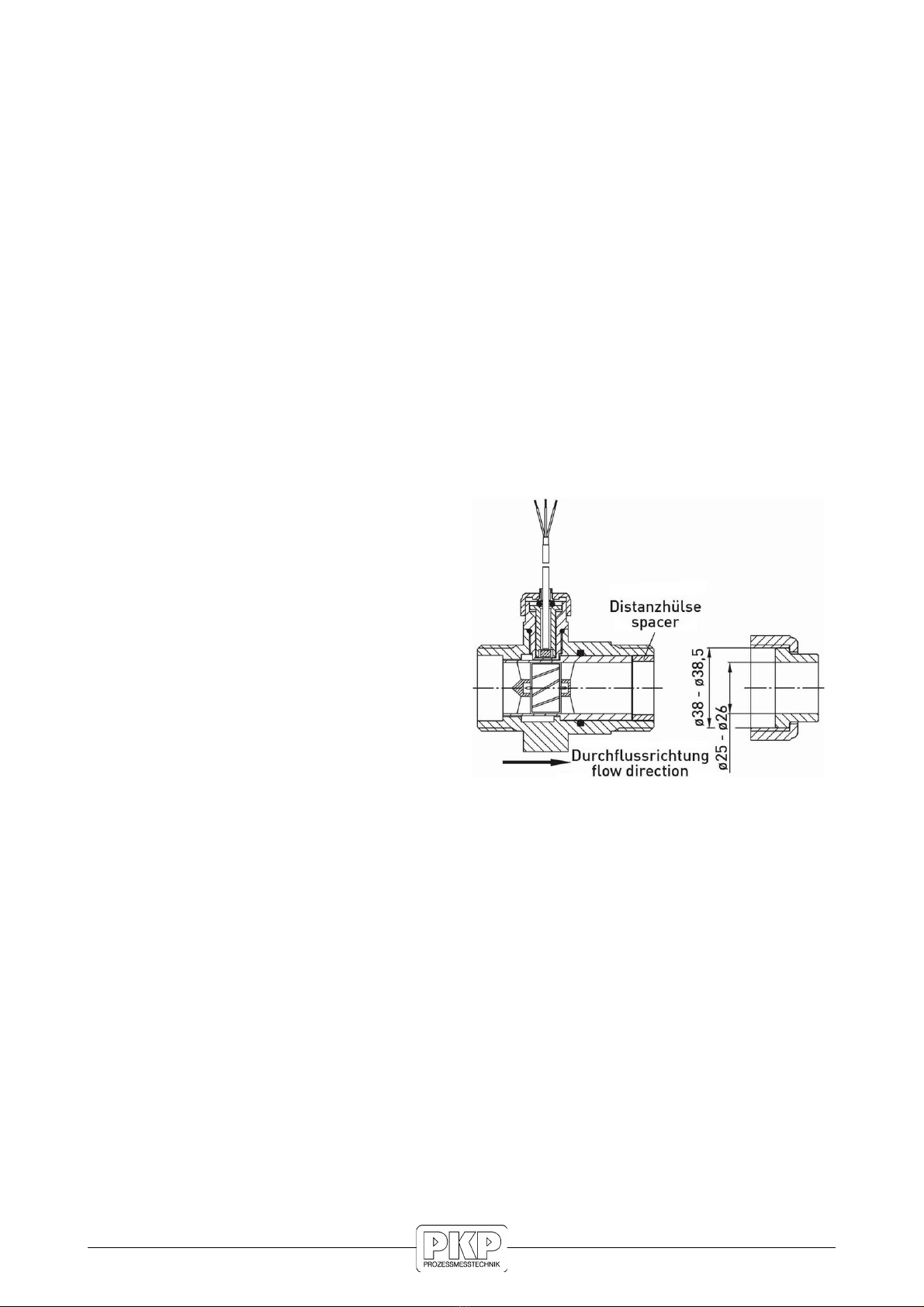
Installation..............................................................................................................................5
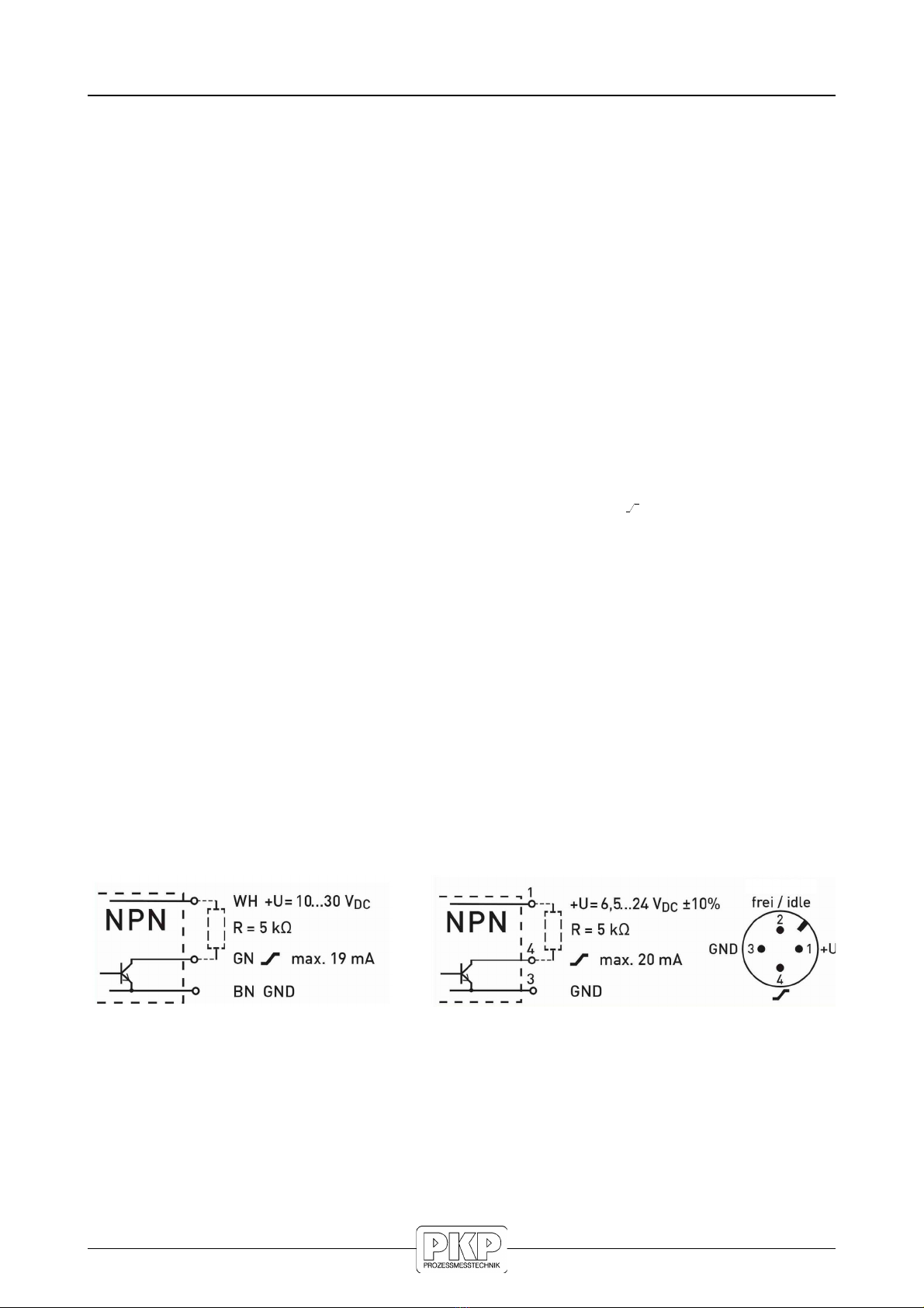
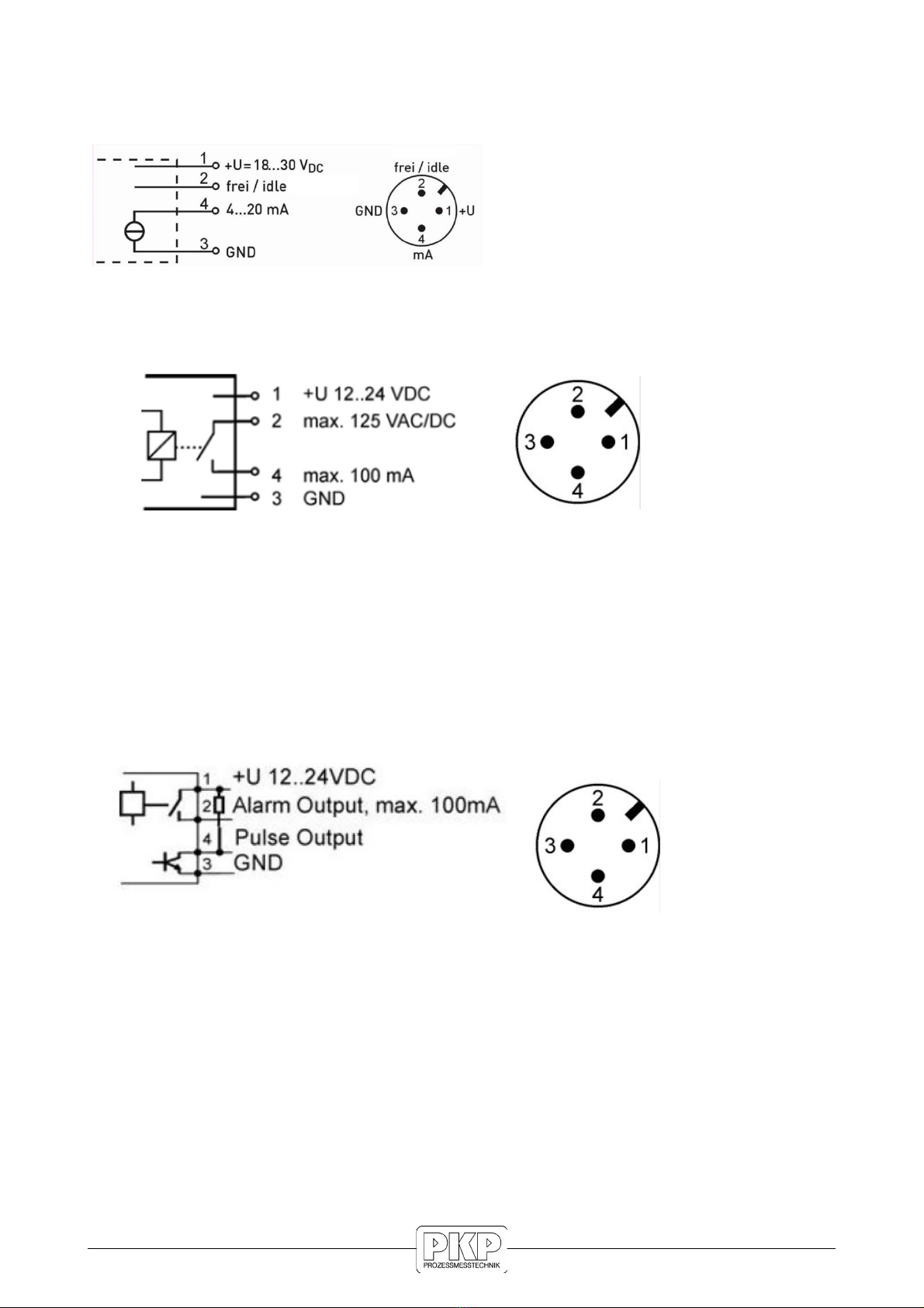
Electrical Connection.............................................................................................................8
Replacement of turbine inserted..........................................................................................11
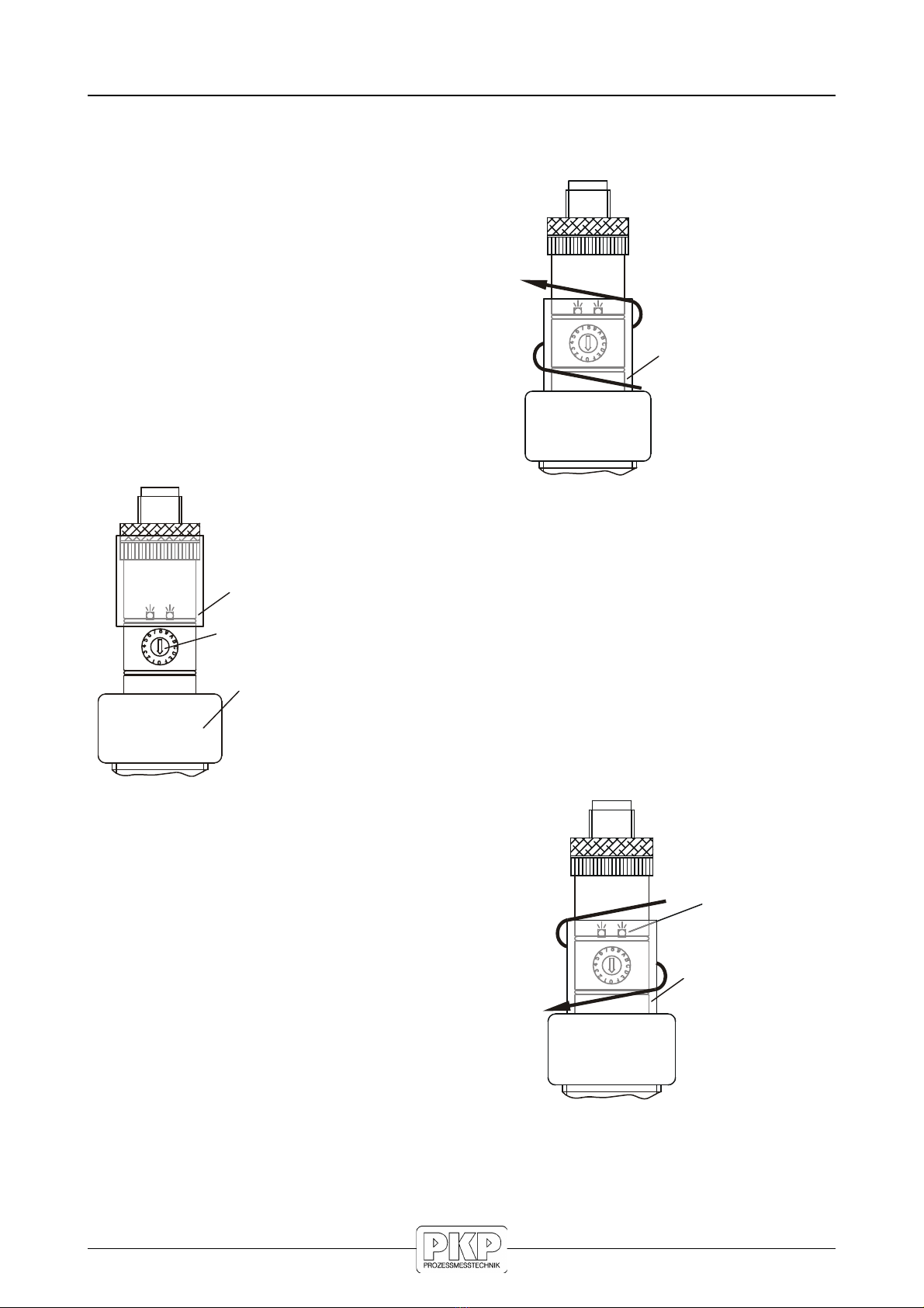
Adjustment of switching points (for option VE und VEP)....................................................12
Cleaning and Maintenance..................................................................................................14
Technical Data.....................................................................................................................15
Materials in contact with fluid...............................................................................................17
Hall-Sensor (P 10) Output Signal Characteristics.............................................................18
Dimensions..........................................................................................................................19
Safety Information
General Instructions
To ensure safe operation, the device should only be operated according to the
specifications in the instruction manual. The requisite Health & Safety regulations for a
given application must also be observed. This statement also applies to the use of
accessories.
Every person who is commissioned with the initiation or operation of this device must have
read and understood the operating instructions and in particular the safety instructions!
The work safety instructions in this manual as well as the safety, accident prevention and
environmental protection regulations generally valid for the work area must be observed.
The liability of the manufacturer expires in the event of damage due to improper use, non-
observance of this operating manual, use of insufficiently qualified personnel and
unauthorized modification of the device.
roper Usage
The flow meters DR08-25 are designed to monitor continuous flow rates of liquids which
do not attack the device materials. All other usage is regarded as being improper and
outside the scope of the device.
In particular, applications in which shock loads occur (for example, pulsed operation)
should be discussed and checked in advance with our technical staff.
The series DR08-25 flow meter devices should not be deployed as the sole agents to
prevent dangerous conditions occurring in plant or machinery. Machinery and plant need
to be designed in such a manner that faulty conditions and malfunctions do not arise that
could pose a safety risk for operators.
DR08-25 Instruction manual 09/2020 page 2

Dangerous substances
For dangerous media such as e.g. Oxygen, Acetylene, flammable or toxic substances as
well as refrigeration systems, compressors, etc. must comply with the relevant regulations
beyond the general rules. Qualified Personnel
The DR08-25 devices may only be installed by trained, qualified personnel who are able to
mount the devices correctly. Qualified personnel are persons, who are familiar with
assembling, installation, placing in service and operating these devices and who are
suitably trained and qualified.
Inward Monitoring
Please check directly after delivery the device for any transport damages and deficiencies.
Additional with reference to the accompanying delivery note the number of parts must be
checked.
Claims for replacement or goods which relate to transport damage can only be considered
valid if the delivery company is notified without delay.
Device description
The flow sensors of the series DR08-25 are transducers for flow rate and total flow
measurement.
Thanks to its particularly compact design, its very wide measuring range and its
convincing measuring accuracy, there are almost unlimited application possibilities.
DR08-25 Instruction manual 09/2020 page 3

Installation
CAUTION! Malfunction due to bubbles!
Gas bubbles which are also formed by cavitation in the medium can cause a
malfunction of the sensor and must be prevented.
Observe the following instructions in order to achieve highest-possible measurement
accuracy and specified output signal:
Before installing the turbine flow monitor flush the pipe carefully. You avoid a blocking
of the turbine caused by particles from the pipe installation.
The installation position of the flow monitor is unreserved. If it is installed into vertical
pipes, the flow direction is preferably from below upward. You must avoid a free
outlet.
The arrow which is placed on the flow monitor () shows the only permitted flow
direction.
In order to achieve the best measurement accuracy, a straight tube in front of the flow
monitor must be retained, min 10 x D . Behind the flow monitor, a straight outlet
tube of 5 x D must be kept.
The internal diameter of the in- and outlet tubes must correspond with the internal
diameter of the flow monitor. Before and behind the stabilization tubes, the line may
be contracted or enlarged.
In practice these instructions often cannot be observed. Then the pulse rate and
the measurement accuracy can be affected.
The flow medium to be monitored should preferably contain as few solid particles as
possible.
Present particles must not exceed a diameter of 0.63 mm. If necessary, install a
screen filter!
The material of the devices is not suitable for monitoring oils. The strength of the used
plastic parts would be considerably reduced.
Attention:
The union nut of the sensor is sealed and must not be opened!
If this component is opened, the fixation of the turbine system loosens and it is
damaged.
Installation in piping:
ow you can install the flow sensor in the piping system which was prepared.
Note:
Only use a suitable sealant for sealing.
If the male thread is to be sealed, make sure that no fibrous sealants (hemp or Teflon
tape) get into the flow.
DR08-25 Instruction manual 09/2020 page 4

Model brass / stainless steel with connection adaptors
(recommended installation type):
At first screw-in the connecting adaptors into the tube.
ow install the turbine. Make sure that the provided seals fit properly and tighten the
union nuts.
Model brass (stainless steel without connection adaptors):
The turbine system fits into the device
casing and is correctly positioned by the two
connecting adaptors. If you do not want to
use connecting adaptors, you must observe
the following instructions:
Your piping system must have a collar
at the outlet side of the device which
prevents slipping of the turbine insert.
Recommended dimensions are
Internal diameter: 25-26 mm
External diameter: 38-38.5 mm
When installing the device, make sure
that the seals fit properly.
DR08-25 Instruction manual 09/2020 page 5

Model plastic with hose nozzles
In the outlet of the device, there is a spacer. Remove it before installation of the hose
nozzle.
Push the hose nozzle with a rotational movement into the device casing. Make sure
that the O-ring is not displaced and tighten the union nut.
Put the hose nozzle into the piping and fix it with suitable means, e.g. with hose band
clips.
Model plastic with gluing or welding adaptors
Glue or weld at first the connecting adaptors to the piping.
ow install the turbine. Make sure that the provided seals fit properly and tighten the
union nuts.
Model plastic without fittings
Install the device without removing the
spacer from the outlet.
Your piping system must have a collar
at the outlet side of the device which
prevents slipping of the turbine insert.
Recommended dimensions are
Internal diameter: 25-26 mm
External diameter: 38-38.5 mm
When installing the device, make sure
that the seals fit properly.
DR08-25 Instruction manual 09/2020 page 6

Electrical Connection
Attention: We recommend using only screened cables. Connect the shield on one side
(the wire ends) on ground.
Electrical connection with 4-pin plu M12x1:
Screw on 4-pin-plug M12x1 to sleeve and tighten plug with a starting torque of max. 1 m
DR08-25 with pulse output:
The output signal of DR08-25 is a flow-proportional frequency signal. The shape of the
signal is a square wave and its amplitude corresponds approximately with the supply
voltage. It is an open collector signal, P - or P P-switching.
The connected electronic instrument should have a loading resistance (pull-up or pull-
down resistor) of 5 k in the inlet.
Schematic representation:
A connection is made with three leads, the supply voltage must be connected between +U
and G D (ground), the output signal can be tapped between and G D. The colour
assignment of the supply cables can be taken from the sketch on the type plate.
Colour code:
B = brown
BK = black
BU = blue
G = green
WH = white
R = resistor
DR08-25 with Hall-sensor and
connectin cable, PN 10:
DR08-25 with Hall-sensor and plu M12x1,
PN 50:
DR08-25 Instruction manual 09/2020 page 7

Connection diagram for electric options:
DR08-25 with analo ue output (option Ax):
DR08-25 with mounted switchin output (option VE):
Pinout:
PI 1: Supply voltage +U 12...24 VDC
PI 2/4: Switching contact max. 125 VAC/DC, max. 100 mA
PI 3: G D (Ground)
breaking with decreasing flow
DR08-25 with mounted switchin output and additional pulse output
(option VEP):
Pinout:
PI 1: Supply voltage +U 12...24 VDC
PI 2: Alarm output max. 100 mA
PI 3: G D (Ground)
PI 4: Pulse output, max. 100 mA
contact opens when flow drops below minimum setting
DR08-25 Instruction manual 09/2020 page 8

Integrated temperature sensor (optional):
Optionally, the flow monitor can be equipped with an integrated temperature sensor.
Connect the wiring as shown in the circuit diagram.
Pt100, 3-wire with connection cable:
Replacement of turbine inserted
Dismount the flow sensor. The sensor housing is sealed and must not be opened.
Press the turbine insert out of the tube piece in flow direction using a flat tool.
The insert fits very tight in the tube piece. You should not use your fingers and never
use a pointed tool to press it out of the tube.
The turbine insert consists of two cylinders of different diameters which must never be
dismounted.
Push the new insert with the small diameter to the front into the pipe section against
the flow direction. Turn the insert in such a way that the webs are not directly beneath
the Hall sensor or the proximity switch. Press the insert into the pipe section up to the
stop. The position will be correct, if the face of the inserts is flush with the pipe section
(applies only to metallic version). Plastic version: push the insert up to the stop, now
do the same with the spacer. The spacer must be flush with the tube piece.
Reinstall the DR08-25 in the piping. Make sure that the provided seals fit properly.
DR08-25 Instruction manual 09/2020 page 9

Adjustment of switching points (for option VE und VE )
You can adjust the switching points with the rotary switch above the red union nut.
Push the sliding sleeve in a rotatin movement to
the top of the casing, until the adjustment bore is
accessible.
Adjust the rotary switch with a small screw driver to the
requested switching point.
There are 16 different rotary switch positions available (0
to F, resting).
After adjustment, you must push the sliding sleeve
again with a rotatin movement down over the
adjustment bore and the two O-rings.
DR08-25 Instruction manual 09/2020 page 10
Sliding sleeve
Sliding sleeve
Rotary switch
Union nut
Sliding sleeve
Control LED
red / yellow

ATTENTION :
The degree of protection IP54 can only be obtained, when the sliding sleeve is seated
correctly and a female plug is placed in position.
Two light emitting diodes are optically signalling the monitoring of the flow.
•Yellow LED: volume flow sufficient = „OK“
•Red LED: shortage of flow,
i.e. volume flow insufficient = „ALARM“
Attention:
For functional safety, the M12 male plug installed on top of the upper casing must not be
screwed off.
Switching point tables:
Switch
position:
0 1 2 3 4 5 6 7 8 9 A B C D E F
Switching
point
decreasing
flow
[l/min]
3 5 6 8 10 12 15 18 20 25 30 35 40 50 70 100
Switching
point
increasing
flow*
5 7 8 10 12 14 17 20 22 27 33 38 44 55 75 105
* The stated values refer to operation with water at 20 °C. Monitoring of fluids with higher
viscosities is possible with the effect of deviations from mentioned values.
DR08-25 Instruction manual 09/2020 page 11

Cleaning and Maintenance
Attention:
The upper union nut (red) is sealed!
It must not be opened.
If this component is opened, the fixation of the turbine
system loosens and it is damaged.
A factory repair will be necessary!
To remove dirt from the flow sensor, you should flush it
with water always in opposite direction to the flow.
Warnin :
A possible blowing out of the device with compressed air must only be carried out in
opposite direction to the flow.
DR08-25 Instruction manual 09/2020 page 12

Technical Data
Turbine flow sensor with pulse output:
PN 10 PN 50
Characteristics measurement device
Measuring range 4...160 l/min*
Accuracy 7 % of reading (≤ 5 l/min)
5 % of reading (> 5 l/min)
Repeatability 0.5 %
Signal output from < 1 l/min
Sensor Hall effect sensor
Characteristics output si nal
Pulse rate / K-factor 65 pulses/l
Resolution 15.4 ml/pulse
Signal shape Square wave signal
P open collector
Signal current, max. 19 mA
Pull-up-resistor 5 kΩ (recommendation)
Electrical characteristics
Supply voltage 10...30 VDC
optional: 4.5…26.5 VDC
6.5...24 VDC 10%
short circuit proof and
reverse polarity protected
Current consumption < 10 mA
Electrical connection 2 m PVC cable,
screened (Tmax = 75 °C)
4-pin plug M12x1
Degree of protection
(E 60529)
IP 54
Process variables
Medium temperature, max.
- Brass 85 °C 85 °C
- Plastic 80 °C (2 bar)
60 °C (5 bar)
30 °C (10 bar)
-/-
- Stainless steel -/- 85 °C
Medium temperature, min. 0 °C, non-freezing
Ambient temperature 0…75 °C 0…85 °C
ominal diameter D 25
ominal pressure P 10 P 50
Particle size in the medium < 0.63 mm
Process connection** G 1¼ male thread
* ot suitable for continuous operation.
** For brass / stainless steel additional fitting required.
DR08-25 Instruction manual 09/2020 page 13

Turbine flow sensors with analo ue output, option Ax:
PN 10 PN 50
Characteristics measurement device
Measuring range
(scaling see type plate)
0...60 l/min*
0...100 l/min*
0...160 l/min*
Signal output from < 1 l/min
Sensor Hall effect sensor
Characteristics analo ue output
Output signal 4...20 mA
Signal current ~ 26 mA
Load max. 250 Ω
Residual ripple 0.2 mAss over the entire range
Type 3-wire, galvanic not insulated,
common G D of power supply and output signal
Electrical characteristics
Supply voltage 18...30 V DC
Current consumption max. 30 mA
Electrical connection 4-pin plug M12x1
Degree of protection
(E 60529)
IP 54
Process variables
Medium temperature, max.
- Brass 80 °C 80 °C
- Plastic 80 °C (2 bar)
60 °C (5 bar)
30 °C (10 bar)
-/-
- Stainless steel -/- 80 °C
Medium temperature, min. 0 °C, non-freezing
Ambient temperature 0…80 °C
ominal diameter D 25
ominal pressure P 10 P 50
Particle size in the medium < 0.63 mm
Process connection** G 1¼ male thread
* ot suitable for continuous operation.
** For brass / stainless steel additional fitting required.
DR08-25 Instruction manual 09/2020 page 14

Materials in contact with fluid
Type PN 10
Brass
PN 10
Plastic PP
PN 50
Brass
PN 50
Stainless steel
Pipe section Brass CW724R PP Brass CW724R Stainless steel
1.4571
Turbine cage PS-ST Xarec® 20 % glass fibre reinforced
Rotor PS-ST Xarec® 20 % glass fibre reinforced
Shaft Stainless steel 1.4539
Bearings Sapphire / PA
Housing for Hall
effect sensor
PS-ST Xarec® 20 % glass fibre
reinforced
Brass CW602
/ CW614
Stainless steel
1.4571
O-ring EPDM
Screen filter (option)
associated O-ring
Stainless steel
1.4301
EPDM
-/- Stainless steel 1.4301
EPDM
Spacer -/- PP -/- -/-
DR08-25 Instruction manual 09/2020 page 15

Hall-Sensor ( N 10) Output Signal Characteristics
Temperature dependency:
Closes output transistor: voltage limitation
Load current:
DR08-25 Instruction manual 09/2020 page 16

Dimensions
DR08-25.S.M.H… (brass housin , PN 10, with connection adaptor):
DR08-25.S.M.M...
(brass housin , PN 50)
DR08-25.S.V.M…
(st. st. housin , PN 50)
DR08-25.S.K.H…
(PP-housin , PN 10)
DR08-25 Instruction manual 09/2020 page 17

DR08-25 with option Ax (analo ue output):
DR08-25 with option VE or VEP (switchin output):
Plastic version: Brass version:
DR08-25 Instruction manual 09/2020 page 18

Flow Measurement and Monitoring
DR08
Turbine Flow Sensor
•for low viscosity media
•high measuring accuracy and resolution
•very low series dispersion
•made of plastic,
brass or stainless steel
•high temperature resistance
•small installation dimensions
•temperature measurement
can be integrated
•ranges 2...40 l/min up to 0,4...25 m³/h
•Pmax 300 bar, Tmax 150 °C
Description:
The flow meters of the DR08 series operate according to the
turbine wheel principle.
The liquid flows into the turbine body and causes a rotor to
rotate in proportion to the flow. Depending on the model, this
rotation is converted into an output frequency by an inductive
proximity sensor or a all sensor.
One of the main features of the DR08 turbine flowmeters is
the very low series scatter of identical devices. This eliminates
the need for individual adjustment of the individual turbines to
the respective downstream electronics, making the DR08
ideally suited for use in series applications
Typical applications:
Due to their design, large measuring range and high
measuring accuracy, the DR08 turbine flowmeters are
suitable for applications in these areas:
• cooling water measurement
• medical technology
• plastics industry
• solar plant
• machine tools
• photo laboratory systems
• tapping and dosing systems
• cooling and heating applications
• heat quantity measurement
PKP Prozessmesstechnik GmbH
Borsigstr. 24 • D-65205 Wiesbaden
S +49 (0) 6122-7055-0 • T +49 (0) 6122 7055-50
[email protected] • www.pkp.de
20200915

Measuring Principle
DR08-15 : meas ring range 2…40 l/min
Axial t rbine flow meter with g ide vanes.
The liquid flowing into the flow meter is divided into four partial
jets by the guide vanes.
These hit the rotor from four
directions and cause it to turn.
Due to the uniform load on the
bearing from four sides, most
of the forces are balanced and
wear is reduced to a
minimum. The extremely hard
bearing materials, sapphire
and tungsten carbide, also
guarantee an exceptionally
long service life.
DR08-25: meas ring range 4…160 l/min
Axial t rbine flowmeter
The liquid flowing into the
flow sensor causes the
turbine wheel to rotate.
Thanks to high-quality
sapphire bearings and low
speeds, the turbine achieves
an exceptionally long service
life. The rotor speed is
converted into an electrical
pulse signal (frequency).
DR08-40: meas ring range 0,4…25 m³/h
Axial t rbine flow meter with partial flow eval ation
A plastic turbine system is located in the centre of the brass
turbine body. Due to its design, there is an annular gap around
the turbine system.
One part of the liquid flow
causes the turbine to rotate,
while the other part flows
unhindered through the
annular gap. The rotor speed
is now converted into an
electrical pulse signal
(frequency). igh-quality
sapphire bearings and low
speeds ensure that the turbine
has an exceptionally long
service life.
Dimensions
PKP Prozessmesstechnik GmbH
Borsigstr. 24 • D-65205 Wiesbaden
S +49 (0) 6122-7055-0 • T +49 (0) 6122 7055-50
[email protected] • www.pkp.de
Flow
Table of contents
Other PKP Accessories manuals
Popular Accessories manuals by other brands

Ursalink
Ursalink EM500 Series quick guide

Honeywell
Honeywell PEHA 940 RS Installation and operating instructions

BRUEL & KJAER
BRUEL & KJAER ASA-069 Series manual

Videk
Videk VISIONSENSOR 2030 user manual

turck
turck uprox + BI4U-EM12WD-AP6X-H1141/3GD manual

Pepperl+Fuchs
Pepperl+Fuchs LUC-M30 Safety instructions