Qualified ersonnel
The DTL04 devices may only be installed by trained, qualified personnel who are able to
mount the devices correctly. Qualified personnel are persons, who are familiar with
assembling, installation, placing in service and operating these devices and who are suit-
ably trained and qualified.
Inward Monitoring
Please check directly after delivery the device for any transport damages and deficiencies.
Additional with reference to the accompanying delivery note the number of parts must be
checked.
Claims for replacement or goods which relate to transport damage can only be considered
valid if the delivery company is notified without delay.
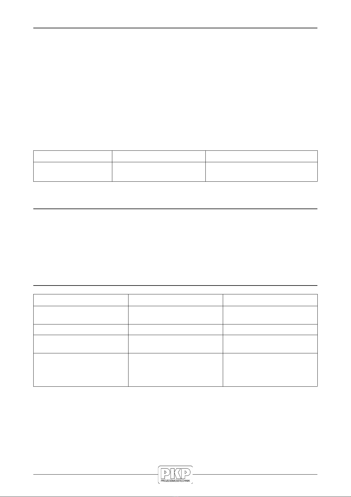
Functional Description
The flow monitors of the type series DTL04 operate according to the calorimetric principle.
The devices switch when a set threshold value is reached. With the calorimetric measur-
ing principle, a temperature-sensitive resistance is heated. The heating process is carried
out by a separate heating resistor.
A flow in the medium dissipates heat from the measuring resistor, the temperature of the
resistor changes and so does its resistance value. This change is evaluated.
However, not only the velocity of the flowing medium, but also its temperature has an
influence on the amount of heat dissipated, so a relation between flow and temperature
must be established. This is done via a second temperature-dependent measuring resistor
in the vicinity of the first one. The second measuring resistor (temperature compensation)
is not heated and is only used for temperature measurement.
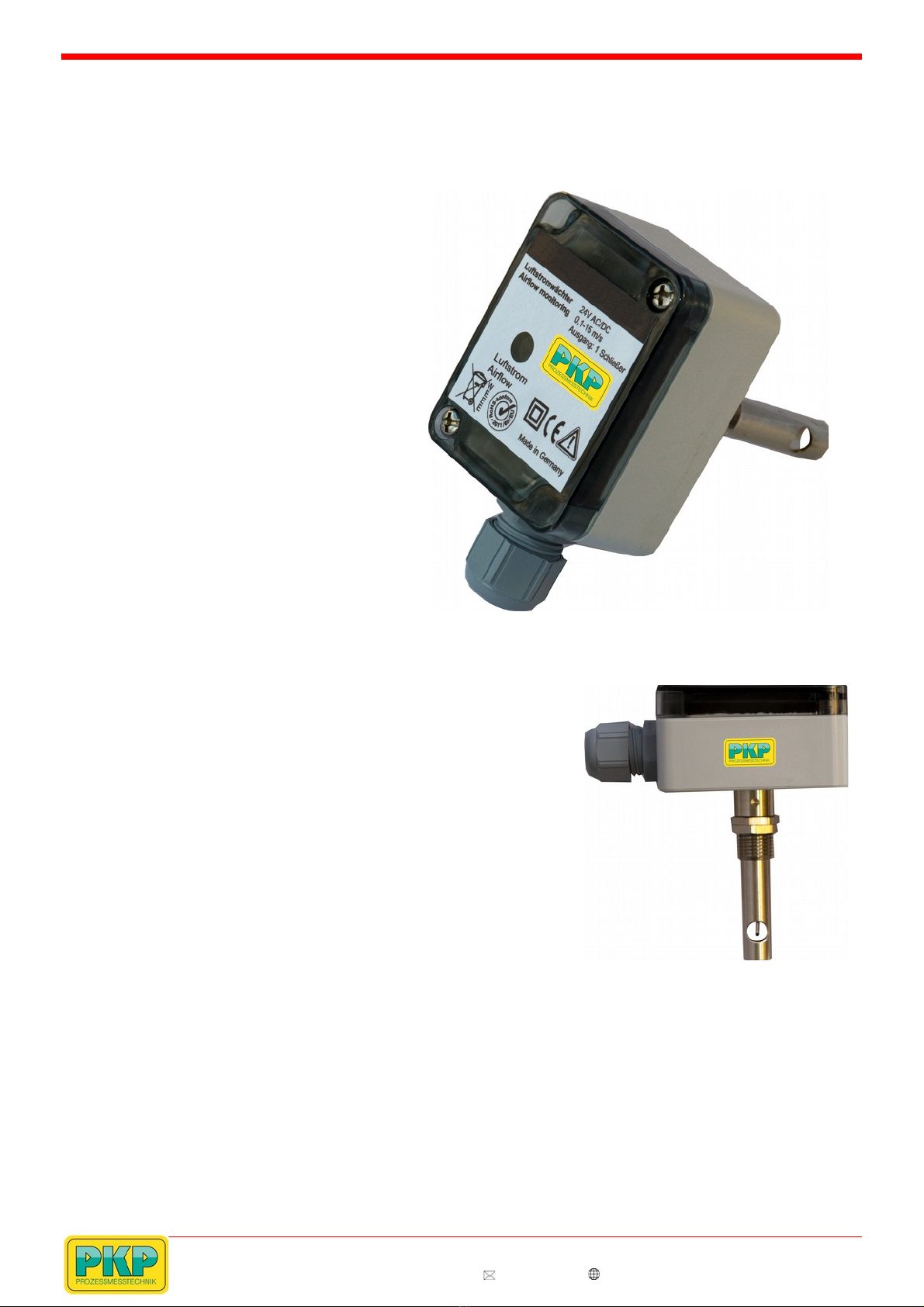
Installation
In order to avoid malfunctions, the following points must be observed:
•The mounting is simple and quick via a flange mounting (for duct mounting) or via
the PG7 or 1/2” threaded connection piece.
•The sensor tip should be located in the middle of the pipe if possible. The gaseous
medium must flow through the transverse hole in the sensor shaft.
•The marking serves as a mounting aid. Align the sensor tube exactly in the duct!
•If the pipes are installed vertically, the direction of flow should be from bottom to
top.
•Observe free inlet distance 5xD (pipe diameter) before the sensor and 3xD outlet
distance after the sensor.
•Screw in the flow monitor only over the hexagon of the sensor housing.
•The flow monitor is independent of the mounting position.
•Optimum measurement results can only be achieved with an optimum installation
arrangement while maintaining the inlet and outlet distances!
DTL04 Instruction manual 07/2019 page 3