PKP DV01 User manual

Instruction Manual
DV01
Gear wheel flow sensor for viscous liquids
PKP Prozessmesstechnik GmbH
Borsigstraße 24
D-65205 Wiesbaden- ordenstadt
Tel.: ++49-(0)6122-7055-0
Fax: ++49-(0)6122-7055-50
Email: info@pkp.de

Table of Contents
Safety Information..................................................................................................................2
General Information...............................................................................................................3
Functional Description...........................................................................................................3
Installation and Removal........................................................................................................4
Commissioning.......................................................................................................................5
Pipe and Plate Connection....................................................................................................5
Tightening Torques for the Connection Plates......................................................................5
Maintenance and Filtration....................................................................................................6
Return Shipment....................................................................................................................6
Electrical Connection.............................................................................................................6
Safety Information
General Instructions
To ensure safe operation, the device should only be operated according to the specifica -
tions in the instruction manual. The requisite Health & Safety regulations for a given
application must also be observed. This statement also applies to the use of accessories.
Every person who is commissioned with the initiation or operation of this device must have
read and understood the operating instructions and in particular the safety instructions!
The liability of the manufacturer expires in the event of damage due to improper use, non-
observance of this operating manual, use of insufficiently qualified personnel and unau-
thorized modification of the device.
roper Usage
The float-type flow meters DS10 are designed to monitor continuous flow rates of liquids
or gases which do not attack the device materials. All other usage is regarded as being
improper and outside the scope of the device.
In particular, applications in which shock loads occur (for example, pulsed operation)
should be discussed and checked in advance with our technical staff.
The gear wheel flow sensors of the DV01 series are characterised by reliable function and
simple operation. The devices of the DV01 series are mainly used for consumption meas-
urements and for the control of filling processes as well as for lubrication point monitoring.
Machinery and plant need to be designed in such a manner that faulty conditions and mal-
functions do not arise that could pose a safety risk for operators.
Dangerous substances
For dangerous media such as e.g. Oxygen, Acetylene, flammable or toxic substances as
well as refrigeration systems, compressors, etc. must comply with the relevant regulations
beyond the general rules.
DV01 Instruction manual 09/2019 page 2

Qualified ersonnel
The DV01 devices may only be installed by trained, qualified personnel who are able to
mount the devices correctly. Qualified personnel are persons, who are familiar with
assembling, installation, placing in service and operating these devices and who are suit-
ably trained and qualified.
Inward Monitoring
Please check directly after delivery the device for any transport damages and deficiencies.
Additional with reference to the accompanying delivery note the number of parts must be
checked.
Claims for replacement or goods which relate to transport damage can only be considered
valid if the delivery company is notified without delay.
General Information
Please observe all instructions in this operating manual to ensure trouble-free operation of
the flow sensors. PKP accepts no liability for damage caused by non-compliance with
these instructions.
The devices my only be opened within the warranty period after consultation and approval
by PKP.
Functional Description
Inside the DV01 there are two gear wheels, which are low-friction mounted. They are
driven by the liquid flow during operation. This gear wheel movement is sensed contact-
lessly by a sensor located in the cover and converted into electrical signals. These signals
are transmitted to the connected display unit via a preamplifier plugged into the housing
cover.
DV01 Instruction manual 09/2019 page 3

1. Cover
2. Housing
3. Gear wheel
4.bearing journal
5. Bearing bush
6. Sensor
7. Plug with preamplifier
8. O-ring
Installation and Removal
The gear wheel flow meter has been tested at the factory before delivery and is ready for
operation immediately after installation and connection of the electrical cables. The built-in
meter should be accessible for visual inspection at any time during operation.
Attention: In the event of damage to the gear wheel flow meter, a pressure safety
device must be provided in the system to prevent the maximum permissible
pressure of the volume sensor or other components in the system from being
exceeded (pressure relief valves). It must be ensured that the flow meters are only
held by the housing during installation and transport, never by the plug.
DV01 Instruction manual 09/2019 page 4

Commissioning
Depending on the type of connection, the device is connected to the system via a connec-
tion plate or by means of pipe connections located in the housing.
Attention: Only pipes and connections that are approved for the expected pressure
range may be used. The instructions of the respective manufacturer must be
observed.
The device must be installed in such a way that it is not subjected to any imper-
missible vibrations.
Installation above hot parts is not permitted as any leaking liquids may ignite.
During commissioning, the device must be checked for leaks under operating
conditions.
ipe and late Connection
•Thoroughly clean the piping system before installing the gear wheel flow meter.
•Connect the piping to the inlet and outlet of the meter. Follow the instructions of the
respective manufacturer.
•During installation, make sure that no sealant enters the inside of the pipes.
Attention: The gear wheel flow meter must not be braced during installation.
•After commissioning the system, check all connections for leaks.
late connection
•Before mounting the gear wheel flow meter, sufficiently clean the piping system.
•Attach the connection plate to the intended position in the system.
Attention: Make sure that the seals are seated correctly! The connection surface
must be free of dirt, paint residues etc. during installation!
Tightening Torques for the Connection lates
ominal size DV01.1A/E DV01.3A DV01.4A
Tightening torque m - 120 -
DV01 Instruction manual 09/2019 page 5

Maintenance and Filtration
To avoid problems with contamination, we recommend the installation of a fine filter unit of
20 µm.
The DV01 volume sensors are basically maintenance-free. However, it is advisable to
send the devices to the factory for inspection at certain intervals, especially in the case of
critical avoidance with high viscosity or very high loads. This avoids major damage, which
could be causes, for example, by blocking the bearings.
Return Shipment
When returning devices to the factory, please note that inspections and repairs will only be
carried out if a safety data sheet of the medium used is enclosed and the devices have
been flushed beforehand.
In case of non-observance, the goods will be returned carriage forward.
These precautions are taken to protect our personnel. Thank you for your understanding.
Electrical Connection
DV01 Instruction manual 09/2019 page 6

Flow Measurement and Monitoring
DV01
Gear Wheel Flow Sensor
for Viscous Liquids
for OEM pplications
•for media with viscosities
between 20-4000 cSt
•low-cost version
•aluminium- or
stainless steel version
•low pressure loss
•high compressive strength
•small mounting dimensions
•any flow direction
•measuring ranges: 0,02...4 l/min up to 1...200 l/min
•Pmax: 200 bar, Tmax: 80 °C
Description:
The DV01 measuring system consists of a pair of gearwheels
which, according to the gear wheel pump principle are
rotated by the flowing liquid.
The gear wheel bearings are constructed as radial and axial
plain bearings (in the case of the DV01.1 and DV01. , the
DV01.2 uses ball bearings). A magneto resistive measuring
system hermetically sealed from the measuring chamber
senses the rotation of the gear wheels and converts it into a
pulse train. The gear wheel flow meter DV01 causes a very
low pressure drop and makes especially little noise.
Typical applications:
The gear wheel flow meters DV01 are mainly used for con-
sumption measurement, the control of dosing applications
and for monitoring lubricating points. Because of their small
dimensions and their low price they are especially suited for all
kinds of OEM applications.
PKP Prozessmesstechnik GmbH
Borsigstr. 24 • D-65205 Wiesbaden
S +49 (0) 6122-7055-0 • T +49 (0) 6122 7055-50
[email protected] • www.pkp.de
20181128

Models and Measuring Ranges:
Type Measuring
range
[l/min]
iscosity
range
[cSt]
Connection Measuring
volume
[ml/pulse]
Resolution
[pulse/l]
DV01.0 0,02- 4 20…4000 G 1/4 female 0,04 25000
DV01.1 0,25…10 20…4000 G /8 female 0,2 5.000
DV01.2 0,16…16 20… 000 G /8 female 0,245 4.082
DV01. 1…65 20…4000 G /4 female 2 500
DV01.4 1…200 20…4000 G 1 female 5,2 191,5
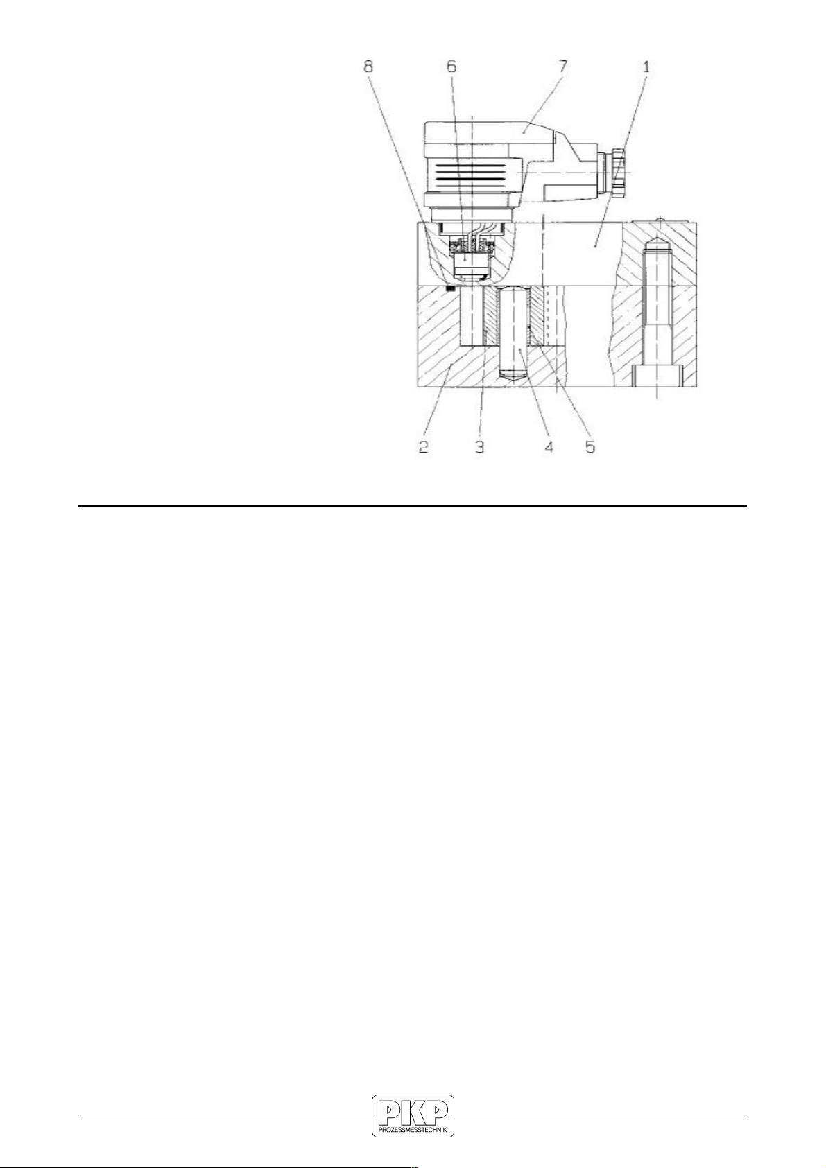
Material:
Type Housing Gear wheels Bearings
DV01.0A aluminium
anodized
stainless steel
1.4462
ball bearings
DV01.0E stainless steel
1.4404
stainless steel
1.4462
ball bearings
DV01.1A aluminium
(anodized)
steel plastic plain bearings
DV01.1E stainless steel
1.4404
stainless steel
1.4462
plastic plain bearings
DV01.2A aluminium
(anodized)
steel ball bearings
DV01. A aluminium steel multilayer plain bearing
DV01.4A aluminium steel ball bearings
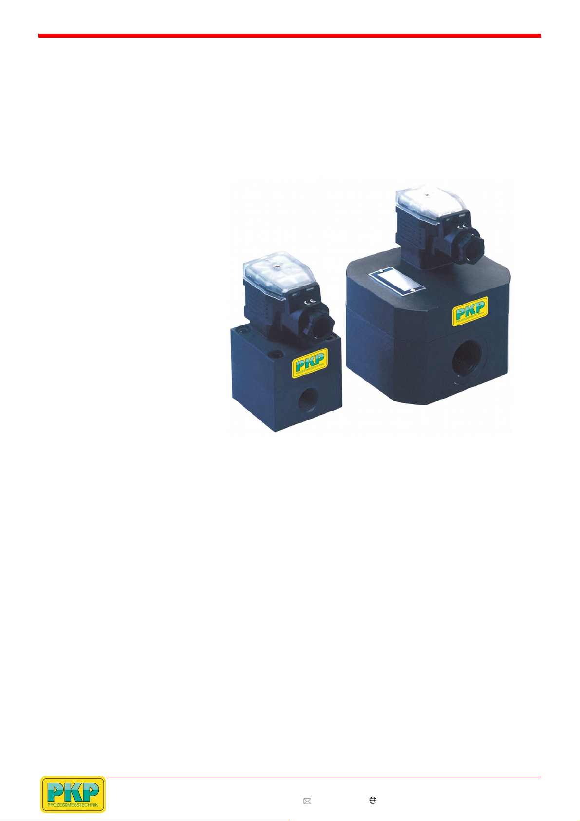
Dimensions:
DV01.0A / DV01.0E: b = 55 mm, t = 55 mm, h = 46 mm
DV01.1A und DV01.1E: b = 55 mm, t = 65 mm, h = 108 mm
(DV01.2A: like DV01.1A, but housing b = 55 mm, t = 65 mm,
h = 108 mm)
DV01. A: b = 90 mm, t = 100 mm, h = 7 mm
DV01.4A: b = 120 mm ; t = 170 mm ; h = 105 mm
Order Code:
Order number: D 01.
Gear wheel flow sensor
1A. 0. 0
Measuring ranges:
0A = 0,02…4 l/min, aluminium
0E = 0,02…4l/min, stainless steel
1A = 0,25…10 l/min, aluminium
1E = 0,25…10 l/min, stainless steel
2A = 0,16…16 l/min, aluminium
A = 1…65 l/min, aluminium
4A = 1…200 l/min, aluminium
Display:
0 = without display
DVA= prepared for plug-on display DVA
(data sheet on the following pages)
Options:
0 = without
1 = please specify in plain text
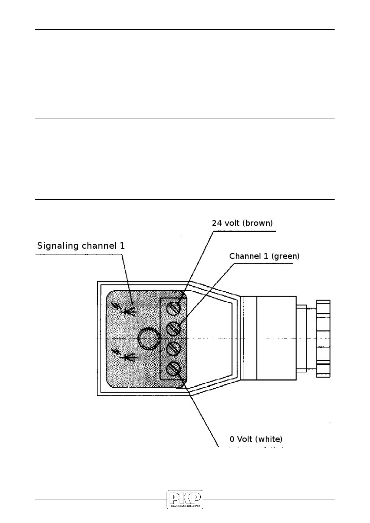
Electrical Connection:
Technical Data:
Max. pressure:
DV01.0A: 200 bar
DV01.0E: 160 bar
DV01.1A and DV01.1E: 160 bar
DV01.2A: 160 bar
DV01. A: 160 bar
DV01.4A: 80 bar
Medium temperature range: −10 °C…+80 °C
Accuracy:
DV01.0A and DV01.0E: ±2 %
DV01.1A and DV01.1E: ± %
DV01.2A: ±0, %
DV01. A: ±2,5 %
DV01.4A: ±1 %
Weight:
DV01.0A and DV01.0E: 0,5 kg
DV01.1A and DV01.1E: 0,5 kg
DV01.2A: 0,7 kg
DV01. A: 1,9 kg
DV01.4A: 6 kg
Supply voltage: 12… 0 VDC,
protected polarity
Power consumption: 0,9 W
Output signal: square wave pulses,
min. 0,8 x UB,
duty cycle
1:1 (±15 %)
Protection class: IP65
PKP Prozessmesstechnik GmbH
Borsigstr. 24 • D-65205 Wiesbaden
S +49 (0) 6122-7055-0 • T +49 (0) 6122 7055-50
[email protected] • www.pkp.de
Flow
This manual suits for next models
9
Table of contents
Other PKP Accessories manuals
Popular Accessories manuals by other brands

Burkert
Burkert 8020 operating instructions

Microtek
Microtek ADF-600EL Installation and operation manual

Tobii Pro
Tobii Pro Glasses 2 quick start guide

Immergas
Immergas 3.030906 Instruction and warning book

Lanaform
Lanaform Aroma Design instruction manual

Spectral Engines
Spectral Engines NIRONE quick guide