Placid Industries PS-12-MC User manual

6-5/8" 8
7
6
8"
4"
1
2
5
3
PLACID
CONSTANT CURRENT
POWER SUPPLY
4
The power supply is suitable for Placid Industries brakes up to 220 lb.-in. & clutches up to 130 lb.-in. torque. The power supply is a
constant current type, with a 3/4 turn potentiometer for setting output current from 0% to 100%. The cutput current can also be
controlled with a 0-10 Volt Input Signal or Follower Arm Potentiometer. The SPAN adjustments set maximum and minimum current
levels.
Input : 120 Volts A.C. 50 / 60 Hz., fused at 1 ampere
Output: PS-12-MC, 0-12 volts D.C., 1.25 amps, 15 watts
PS-24-MC, 0-24 volts D.C., 0.75 amps, 22 watts
Fused at 2 amperes (internal)
0-10 Volt Input Resistance: 2000 ohms
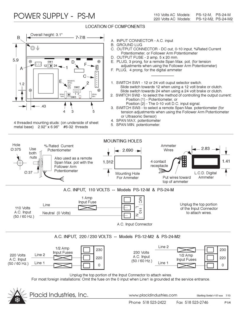
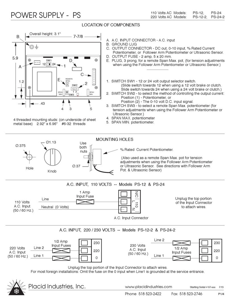
1. % RATED CURRENT potentiometer
2. Current SPAN MAX. potentiometer
3. Current SPAN MIN. potentiometer
4. LED 'Power On' light
5. L.C.D. digital ammeter
6. On underside of case: SWITCH for
Manual (Potentiometer) or
0-10 volt control & Follower control.
7. Terminal Strip for :
1) D.C. Output for brake or clutch coil ( + , - )
2) Ground ( )
3) 0-10 Volt Input Signal ( 0-10v, COM. )
4) Follower Arm Potentiometer
8. A.C. input, A.C. power On/O switch, input fuse
POWER SUPPLY
Specify 12 or 24 Volts D.C.
MODEL: PS - ( voltage ) - MC
SPECIFICATIONS
07-xxx 1/07
Placid Industries
Lake Placid, NY
++
COIL OUTPUT (dc)
GREEN
CONTROL
INPUT
FOLLOWER POT
0-10v COM
PLACID
INDUSTRIES
Phone 518 523-2422
www placidindustries.com
P1/4

+
+
COIL OUTPUT (dc) INPUT
GREEN
INITIAL SET UP - When Using Manual (Potentiometer) Control:
1) Determine the 100% rated current of the brake (or clutch) from the data sheet, or estimate it from the formula:
100% rated current =(rated voltage) /(coil resistance, ohms)
The rated voltage is listed on the label of the brake or clutch.
2) For safety, disconnect the A.C. power.
3) Set 'SWITCH' (on underside of case) to position 2, 'FRONT PANEL POTENTIOMETER' position, so the output
current is controlled by the % Rated Current Potentiometer.
4) Set the SPAN MAX. potentiometer fully counter-clockwise (for minimum output current).
5) Connect A.C. power.
6) Set the % RATED CURRENT potentiometer to 100% (for maximum output current).
7) SPAN MAX. - Turn the SPAN MAX. potentiometer clockwise until output current equals the 100% rated current of
the brake (or clutch).
8) SPAN MIN. - Set the % RATED CURRENT potentiometer to 10%. Adjust the SPAN MIN. potentiometer until the
output current is 10% of rated current.
9) Recheck Steps 6 - 8.
ADJUSTMENTS - When Using Manual (Potentiometer)
Control:
% RATED CURRENT POTENTIOMETER - To control
output current, from 0% to 100%.
SPAN MAX. -Sets the maximum output current. Is a
15 turn potentiometer. Use the miniature plastic
screwdriver provided to make adjustments.
SPAN MIN. - Sets the output current to zero when the
% RATED CURRENT potentiometer is set to zero. Is a
15 turn potentiometer. Use the miniature plastic
screwdriver provided to make adjustments.
POWER SUPPLY -PS-MC
INSTRUCTIONS - MANUAL (Potentiometer) CONTROL
BRAKE OR
CLUTCH
Ground brake or
clutch case to power
supply, if not already
grounded.
07-xxx 1/10
P2/4
Placid Industries
1580 Lake St., Elmira, NY 14901, USA Phone 518 523-2422 Fax 518 523-2746
www.placidindustries.com
CONTROL
FOLLOWER POT
0-10v COM
MODELS: All enclosed power supplies

+
+
COIL OUTPUT (dc) INPUT
GREEN
CONTROL
FOLLOWER POT
0-10v COM
MODELS: All enclosed power supplies
INITIAL SET UP - When Using 0-10 Volt Control:
1) Determine the 100% rated current of the brake (or clutch) from the data sheet, or estimate it from the formula:
100% rated current =(rated voltage ) /(coil resistance, ohms)
The rated voltage is listed on the label of the brake (or clutch).
2) For safety, disconnect the A.C. power.
3) Set 'SWITCH' (on underside of case) to position 1, '0-10v CONTROL' so the output current is controlled by the
0-10 volt D.C. input signal.
4) Set the SPAN MAX. potentiometer fully counter-clockwise, approximately 15 turns, or until it clicks (for minimum
output current).
5) Connect A.C. power.
6) Set your 0-10 volt signal to 10 volts. (for maximum output current).
7) SPAN MAX. ADJ. - Using the miniature plastic screwdriver, turn the SPAN MAX. potentiometer clockwise until the
output current equals the 100% rated current of the brake (or clutch).
8) SPAN MIN. - Set your 0-10 volt signal to 1 volt. Adjust the SPAN MIN. potentiometer until output current is 10%
of rated current.
9) Recheck Steps 6 - 8.
ADJUSTMENTS - When Using 0-10 Volt Control:
0-10 VOLT INPUT SIGNAL - Output current is
proportional to the user's 0-10 volt input signal.
At 0 volts, output current is 0. At 10 volts, output
current is maximum.
SPAN MAX. -This 15 turn potentiometer sets
the maximum output current level.
SPAN MIN. - This 15 potentiometer sets the
output current to zero when the 0-10 volt signal
is zero volts.
POWER SUPPLY -PS-MC
INSTRUCTIONS -0-10 VOLT CONTROL
+
Ground brake or
clutch case to power
supply, if not already
grounded.
Computer
or PLC
07-xxx 1/10
P3/4
Placid Industries
1580 Lake St., Elmira, NY 14901, USA Phone 518 523-2422 Fax 518 523-2746
www.placidindustries.com
BRAKE
OR
CLUTCH

P4/4
Placid Industries
1580 Lake St., Elmira, NY 14901, USA Phone 518 523-2422 Fax 518 523-2746
www.placidindustries.com
Output Connector On Rear
When using a FOLLOWER ARM POTENTIOMETER:
Swing the follower arm into the inactive region. If this is not
possible, then disconnect the wiper using a switch or relay.
When the wire is connected, output current is controlled by the
follower arm potentiometer.
With the wire disconnected, power supply output current is zero.
+
+
COIL OUTPUT (dc) INPUT
GREEN
CONTROL
FOLLOWER POT
0-10v COM
BRAKE
OR
CLUTCH
FOLLOWER ARM
POTENTIOMETER
Switch or
Relay Contacts
Output Connector On Rear
When using 0 - 10 VOLT CONTROL:
If the signal voltage cannot be brought to 0, then use a switch or
relay to interrupt the 10 volt signal.
When the wire is connected, output current is controlled by the
0-10v signal.
With the wire disconnected, power supply output current is zero.
+
+
COIL OUTPUT (dc) INPUT
GREEN
CONTROL
FOLLOWER POT
0-10v COM
+
Computer
or PLC
BRAKE
OR
CLUTCH
DO NOT power up & power down the AC input. DO NOT interrupt the DC output wires.
POWER SUPPLY PS-MC
Switch or
Relay
Contacts
+
D.C.
OUT
Output Connector On Circuit Board
% Rated Current
Potentiometer
CW
WHITE
YELLOW
ORANGE
CW (0v 10+)
When using MANUAL (Potentiometer) control:
Use a switch or relay to interrupt the yellow wire to the % Rated
Current Potentiometer (the wire to the wiper).
When the wire is connected, output current is controlled by the
% Rated Current Potentiometer.
With the wire disconnected, power supply output current is zero.
Enclosed Models:
Remove case cover
for access to circuit
board & output
connector.
Switch or
Relay
Contacts
BRAKE
OR
CLUTCH
INSTRUCTIONS - HOW TO REPEATEDLY CYCLE BETWEEN 0 AMPERES & ANY CURRENT LEVEL
This manual suits for next models
1
Table of contents
Other Placid Industries Power Supply manuals