120 Volts A.C. input
PS-12 : 0-12 VDC output
PS-24 : 0-24 VDC output
220 Volts A.C. input
PS-12-2 : 0-12 VDC output
PS-24-2 : 0-24 VDC output
YELLOW
ORANGE
INITIAL SET UP - When Using Manual (Potentiometer) Control:
1) Determine the 100% rated current of the brake (or clutch) from the data sheet, or calculate it from the formula:
100% rated current = (rated voltage) / (coil resistance, ohms)
The rated voltage is listed on the label of the brake or clutch.
2) For safety, disconnect the A.C. power.
3) Set SWITCH SW2 to position 1, so the output current is controlled by the % Rated Current Potentiometer.
Set SWITCH SW3 towards the edge of the circuit board to select the on-board Span Max. Potentiometer.
4) Set the SPAN MAX. potentiometer fully counter-clockwise (for minimum output current).
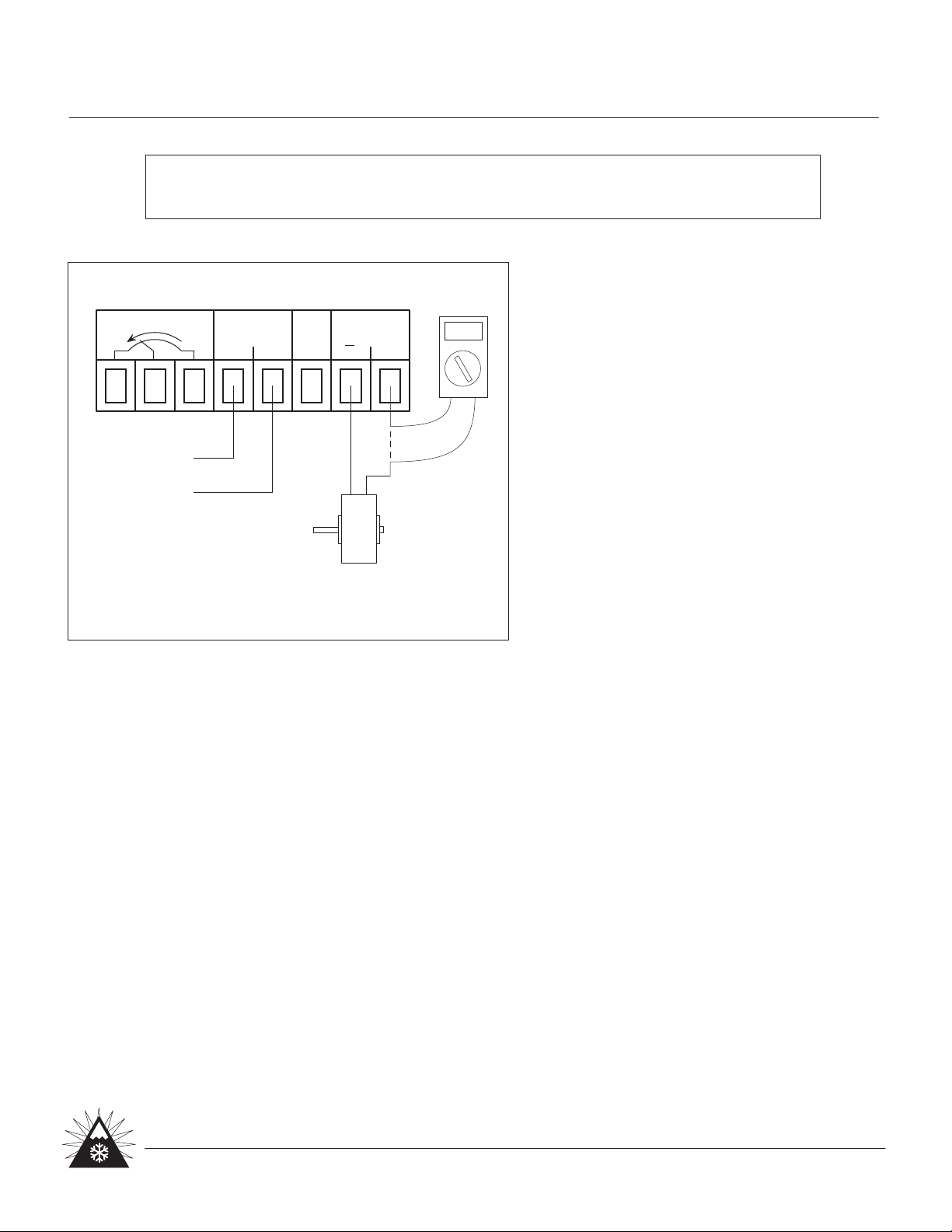
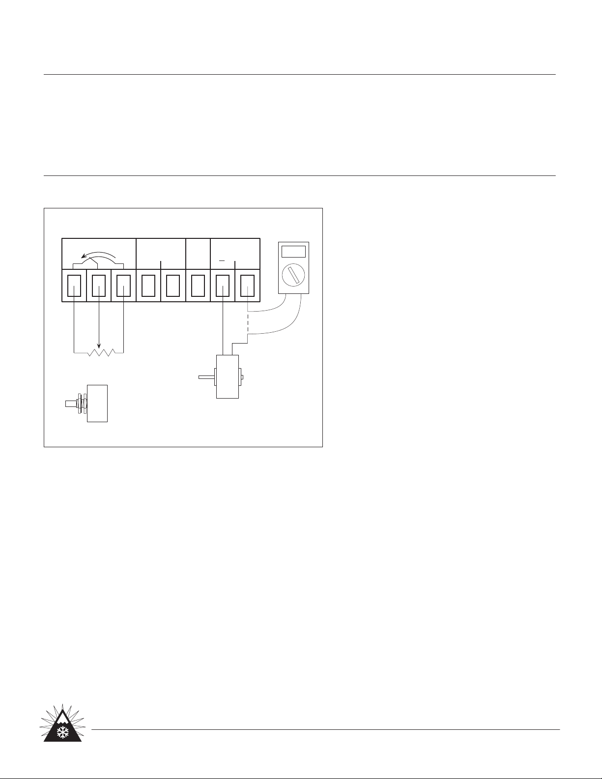
5) Temporarily connect a (customer supplied) ammeter in series with the brake (or clutch). (See wiring diagram.)
6) Connect A.C. power.
7) Set the % RATED CURRENT potentiometer to 100% (for maximum output current).
8) SPAN MAX. - Turn the SPAN MAX. potentiometer clockwise until your ammeter displays the current level
corresponding to the 100% rated current of the brake (or clutch).
9) SPAN MIN. - Set the % RATED CURRENT potentiometer to 10%. Adjust the SPAN MIN. potentiometer until your
ammeter shows the power supply output current is at 10% of rated current.
10) Recheck Steps 7 & 8.
11) Disconnect your (customer supplied) ammeter. Reconnect the brake (or clutch) to Output Connector.
Unplug the top portion of the
Output Connector to attach wires.
AMMETER
WHITE
ADJUSTMENTS - When Using Manual
(Potentiometer) Control:
% RATED CURRENT POTENTIOMETER - The
remotely mountable potentiometer controls the
desired output current, and is adjustable from 0%
to 100%. This is used to control output torque.
SPAN MAX. - Sets the maximum output current.
The 10 turn potentiometer is mounted on the
circuit board. Use the miniature plastic
screwdriver provided to make adjustments.
SPAN MIN. - Sets the output current to zero
when the % RATED CURRENT potentiometer is
set to zero. The 10 turn potentiometer is
mounted on the circuit board. Use the miniature
plastic screwdriver provided to make adjustments.
POWER SUPPLY - PS
SPECIFICATIONS
INSTRUCTIONS - MANUAL (Potentiometer) CONTROL
Output Current: D.C., constant current type
12 volt: 1.25 amps
24 volt: 0.75 amps
Output Fuse: 2 amperes, located on circuit board.
0-10 Volt Input Resistance: 2000 ohms
% RATED CURRENT
POTENTIOMETER
BRAKE OR
CLUTCH
(for set-up
only)
P2/4
Placid Industries, Inc.
Phone 518 523-2422 Fax 518 523-2746
www.placidindustries.com Starting Serial # 07-1 1/07
+
OUTPUT
0v 0-10v
0-10 INPUT
NC
% CURRENT POT
+
OUTPUT CONNECTOR