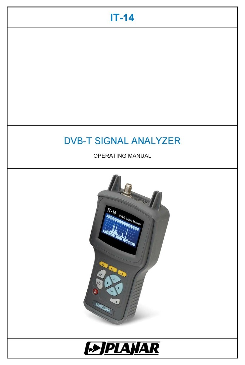
Planar IT-081 User manual

IТ-081
TV LEVEL METER
OPERATING MANUAL

Revision 1.1 of April 4, 2016
2

TABLE OF CONTENTS
1. PRODUCT FAMILY GENERAL INFORMATION .............................................................. 4
2. GENERAL DESCRIPTION AND PRINCIPLE OF OPERATION....................................... 5
2.1. Introduction.................................................................................................................................................................................5
2.2. Safety Precautions.......................................................................................................................................................................5
2.3. Function......................................................................................................................................................................................5
2.4. Environmental Conditions...........................................................................................................................................................6
2.5. Package Contents........................................................................................................................................................................6
2.6. Specifications..............................................................................................................................................................................7
2.7. Design and Operation Overview.................................................................................................................................................8
2.7.1. Principle of Operation...................................................................................................................................................8
2.7.2. Block Diagram..............................................................................................................................................................8
2.7.3. Component Arrangement..............................................................................................................................................9
3. PREPARATION FOR OPERATION....................................................................................... 9
4. OPERATION PROCEDURE............................................................................................. 9
4.1. Controls and Indicators...............................................................................................................................................................9
4.2. Preparation for Measurements...................................................................................................................................................10
4.3. Measurement Procedure............................................................................................................................................................12
4.3.1. General Information....................................................................................................................................................12
4.3.2. Level Measurement Mode ..........................................................................................................................................13
4.3.3. Spectrum Measurement Mode ....................................................................................................................................14
4.3.4. Scan Measurement Mode............................................................................................................................................15
4.4. Data Logger Function ...............................................................................................................................................................16
4.4.1. General Information....................................................................................................................................................16
4.4.2. Channel Plans .............................................................................................................................................................17
4.4.3. Limit Plans..................................................................................................................................................................19
4.4.4. Channel Data Logger..................................................................................................................................................20
4.4.5. Spectrum Data Logger................................................................................................................................................22
4.4.6. Memory Manager........................................................................................................................................................23
4.5. Self-Test and Configuration Modes ..........................................................................................................................................24
4.5.1. Self-Test......................................................................................................................................................................24
4.5.2. Setting Regional Parameters.......................................................................................................................................25
4.5.3. User Interface Setting .................................................................................................................................................25
4.5.4. Identification Data Readout........................................................................................................................................26
4.6. Operation Controlled by PC......................................................................................................................................................27
4.6.1. General Information....................................................................................................................................................27
4.6.2. PC Configuration Requirements.................................................................................................................................27
4.6.3. Software Installation...................................................................................................................................................27
4.6.4. Starting the Program...................................................................................................................................................27
4.7. Updating Software ....................................................................................................................................................................28
4.7.1. General Information....................................................................................................................................................28
4.7.2. Updating Software via PC...........................................................................................................................................28
4.7.3. Updating Software from Removable Module .............................................................................................................29
4.8. Battery Operation......................................................................................................................................................................29
5. MAINTENANCE.............................................................................................................. 30
6. TROUBLESHOOTING.................................................................................................... 30
7. STORAGE ......................................................................................................................31
8. TRANSPORTATION....................................................................................................... 31
9. LABELING ...................................................................................................................... 31
10. WARRANTY INFORMATION ....................................................................................... 31
3

1. PRODUCT FAMILY GENERAL INFORMATION
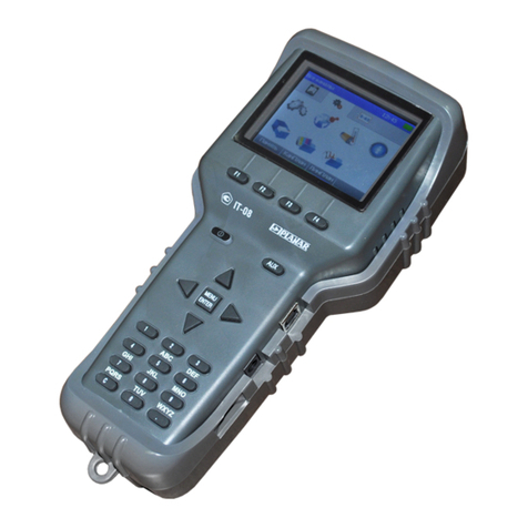
IT-08 is a multifunction handheld compact lightweight measurement instrument
incorporating two components. One of the components, MB-08 Base Unit, remains
invariable and provides color display, control and powering (from batteries or mains
adapter) features. The other component, MC-08x, is one of the removable modules, which
determine measurement functions of the whole instrument.
IT-08 is capable to satisfy all your requirements in radio, cable and satellite, analog
and digital TV measurements.
According to your measurement target, you can easily and quickly plug in one of the
modules into the Base Unit and perform the needed measurements. So, replacing the
modules you can obtain options featuring the following different applications:
IT-081 TV Level Meter (MC-081 module plugged-in), 5 to 900 MHz range.
Measurement of level, video-audio and carrier-noise ratios;
IT-082 DVB-S Signal Analyzer (MC-082 module plugged-in), 950 to 2150 MHz
range. Measurement of BER and MER values for digital satellite (QPSK DVB-S). Powering
LNB SAT. DiSEqC generator;
IT-083 DVB-S/S2 Signal Analyzer (MC-083 module plugged-in), 950 to 2150 MHz
range. Measurement of BER and MER values for digital satellite (QPSK/8PSK DVB-S/S2).
Powering LNB SAT. DiSEqC generator;
IT-084 TDR Cable Reflectometer (MC-084 module plugged-in) for identification and
precision fault location in cables up to 1,600 m in length. Resolution 0.11 m;
IT-086 Optical Power Meter (MC-086 module plugged-in), measuring at –50 dBm to
+20 dBm range and wavelengths 1310 and 1550 nm.
IT-087 DVB-C Signal Analyzer (MC-087 module plugged-in), 45 to
865 MHz range. Support of DVB-C and ITU-T ANNEX A/C. Measurement of carrier level,
C/N and V/A ratios, channel power, MER, BER, and constellation diagram.
IT-088 DVB-T Signal Analyzer (MC-088 module plugged-in), 45 to
865 MHz range. Support of DVB-T and DVB-H with COFDM modulation. Measurements
for analog channels: carrier level, C/N and V/A ratios and for digital channels: channel
power, MER, BER, and constellation diagram.
IT-089 DVB-T/T2 Signal Analyzer (MC-089 module plugged-in), 45 to
900 MHz range. Support of DVB-T/T2 modulation. Measurements for analog channels:
carrier level, C/N and V/A ratios and for digital channels: channel power, MER, BER,
constellation and echo diagrams. Powering of antenna amplifier.
You can purchase MB-08 Base Unit accompanied by any of the module(s), currently
required, at your option. Later on, you can acquire any other module(s) to expand your
measurement abilities.
IT-08 GENERAL FEATURES (similar for all the IT-08 family instruments):
MB-08 dimensions (WxHxD)..................................................................... 90 x 200 x 55 mm
MC-08x dimensions (WxHxD)..................................................................... 60 x 70 x 27 mm
IT-08 weight .................................................................................0.6 kg (including batteries)
Keypad...........................................................................................................made of rubber
Display ....................................................... color graphic LCD 320x240 pixels with backlight
Power supply
internal........................................... NiMH AA rechargeable batteries, 2100 mAh (6 pcs)
external..................................................................................... 12V/0.8A mains adapter
PC compatible interface.......................................................................................... USB port
Operating temperature.....................................................................................−10 to +40 °C
User software update... through USB interface from PC or the MC-08x Removable Module
4

2. GENERAL DESCRIPTION AND PRINCIPLE OF OPERATION
2.1. Introduction
This Operating Manual is intended for introducing the design, functions, and basic
instructions related to operation and servicing of the IT-081 TV Level Meter (Meter).
The IT-081 is designed for control and adjustment of television and broadcasting
distribution networks as well as of separate components of such networks, or other
electronic devices. The Meter allows measurement of channel power and parameters of TV
signal.
The Meter can be used both in laboratory, powered by an external power source, and
in field, powered by batteries. The Meter can also operate as a part of Return Path Test and
Measurement Set.
The reliability of the IT-081 is ensured by fulfillment of regular maintenance
procedures. These procedures and their intervals are described in Section 5.
In this manual the following abbreviations are used:
- PC - Personal Computer;
- CD - Compact Disk;
- LCD - Liquid Crystal Display;
- ADC - Analog-to-Digital Converter;
- IF - Intermediate Frequency.
2.2. Safety Precautions
Thoroughly inspect the product and carefully read the related documentation to get
acquainted with all the safety markings and instructions before you start to operate the
Meter.
WARNING Only trained service personnel aware of the hazards involved should perform
repair on the Meter.
CAUTION Tuning the Meter and replacement of the components that influence the
accuracy of measurements without service personnel is strictly prohibited, since the
components used in the Meter are purpose-made and their replacement will result in
inaccurate operation of the Meter. To exclude the possibility of mechanical damage to the
IT-081, the instructions regarding the storage and transportation (see Sections 7 and 8) of
the Meter must be observed.
2.3. Function
The IT-081 TV Level Meter belongs to the family of IT-08 measurement instruments
and is intended for measurement of the video carrier level of standard TV signal.
The Meter offers the following measurement modes for analog channels: video
carrier to audio carrier (V/A) ratio, and video carrier to noise (C/N) ratio. For digital
channels the measurement modes are the following: channel power and C/N ratio.
The IT-081 can be connected to a personal computer to access additional modes.
The IT-081 operates in spectrum analyzer mode displayed on the built-in LCD. The Meter
allows measuring direct and alternating voltage of the remote power supply of the TV and
broadcasting distribution networks.
The appearance of the Meter and its components are displayed in figures 2.1 and
2.2.
5

Figure 2.1 Figure 2.2
This Operating Manual is made in accordance with the hardware version 02.80.01 for
MB-08 Base Unit and software version 1.2.x.x/1.2.x.x for IT-081.
2.4. Environmental Conditions
Normal operating conditions:
a) ambient temperature (23±5) 0С;
b) relative air humidity (55±25)%;
c) atmospheric pressure 84-106 kPa (630-795 mm Hg);
d) voltage transients correspond to installation category CAT. II.
Rated operating conditions:
a) ambient temperature from -10 to 40 °С;
b) relative air humidity not greater than 90% at 25 ºСtemperature;
c) atmospheric pressure 84-106 kPa (630-795 mm Hg).
2.5. Package Contents
The Meter package includes:
a) MB-08 Base Unit.....................................................1 pc;
b) MC-081 Removable Module ...................................1 pc;
c) Carrying Case.........................................................1 pc;
d) NiMH, AA Batteries.................................................6 pcs;
e) TAV03-1201200 Mains Adapter .............................1 pc;
f) “F”-”F” Adapter........................................................1 pc;
g) USB Cable.............................................................1 pc;
h) Rubber Holster........................................................1 pc;
i) Operating Manual ...................................................1 pc.
The Removable Module (if supplied separately) package includes:
a) МС-081 Removable Module ..................................1pc;
b) “F”-”F” Adapter........................................................1pc;
c) Operating Manual ...................................................1pc.
6

2.6. Specifications
Operating frequency range ...............................................................................5 to 900 MHz
Resolution.................................................................................................................125 kHz
Channel allocation standard .................................... China, PAL B/G, PAL Ireland, PAL UK,
.................................................................................. Secam D/K, France, NCTA, Australian
Input parameters:
a) input impedance within operating frequency range: 75 Ohm;
b) input impedance for frequencies up to 50 Hz at least: 200 kOhm.
Allowed resulting value of AC input voltage for frequencies over 5 MHz: 3 V.
Allowed resulting value of AC and DC input voltage for frequencies
under 5 MHz: 150 V.
Built-in attenuator....................................................................................................20, 40 dB
Input mismatch attenuation
- Input attenuator off ............................................................................................ 14 dB
- Input attenuator on ............................................................................................ 18 dB
Level measurement range with manual attenuator setting
- Input attenuator off ............................................................................... 30 to 90 dBμV
- Input attenuator 20 dB ........................................................................ 50 to 110 dBμV
- Input attenuator 40 dB ........................................................................ 70 to 126 dBμV
Measurement level resolution ..................................................................................... 0.1 dB
Accuracy within 30-126 dBµV level range .................................................................±1.5 dB
Accuracy at operating temperature............................................................................±2.2 dB
Measurement channel passband for -3 dB level...............................................230 ± 60 kHz
Frequency indication............................................................................. 6 characters on LCD
Channel number indication ................................................................... 3 characters on LCD
Signal level indication ........................................................................... 4 characters on LCD
Warm-up time ............................................................................................................ 10 min.
IT-081 can be powered by
- AC circuit with 110-240 V voltage, 50 ± 0.5 Hz frequency with no more than
5% harmonic content, via PS12/0.8 Mains Adapter;
- external DC source with 12 ± 0.6 V voltage, and no more than 0.5 V ripple;
- batteries with capacity at least 2100 mAh;
Current consumed from external power source or batteries ......................................... 0.8 А
Continuous stable operation under normal conditions
(when powered by external source).............................................................................24 hrs
Battery duration under normal conditions
(2100 mAh battery capacity) ......................................................................................6 hours
Mean time between failures, no less than.......................................................... 10000 hours
Average lifetime, no less than.................................................................................... 5 years
Dimensions ................................................................................................... 200x90x55 mm
Shipping dimensions................................................................................... 400x300x90 mm
Weight.......................................................................................................................... 0.6 kg
Weight in package ....................................................................................................... 2.2 kg
7

2.7. Design and Operation Overview
2.7.1. Principle of Operation
The TV Level Meter is a super heterodyne receiver with triple frequency conversion
(auto or manual frequency tuning). Channel power is measured by means of analog-to-
digital converter (ADC) after signal peak detection at output of logarithmic detector of the
amplifier of the third IF. The principle of spectrum analyzer is based on sequential analysis
method with spectrum indication on the LCD of the Meter or on PC.
The view displayed on the screen in the spectrum analyzer mode is the signal
frequency bar-graph. The mode of signal level measurement in a frequency point displays
the numeric value of the signal level, V/A and C/N ratios.
2.7.2. Block Diagram
The block diagram of IT-081 is shown in figure 2.3.
Figure 2.3
After the Low-Pass Filter (LPF), the input signal if necessary is reduced by the two
Attenuators (A1) and (A2). Then it is transformed into the first IF signal by the Mixer (M1)
and adjustable Local Oscillator (LO1). The first IF is 1216 MHz. Then the signal is passed
through the Bandpass Filter (BPF1). Local Oscillator (LO1) is implemented according to
circuit of the frequency synthesizer with phase lock loop.
The signal of the first IF is converted by the 1178 MHz Local Oscillator (LO2) and the
Mixer (M2) to the second IF, and is further filtered at 38 MHz frequency by BPF2. The
signal of the second IF is converted by the 27.3 MHz Local Oscillator (LO3) and the Mixer
(M3) to the third IF, and further filtered at 10.7 MHz frequency by BPF3, which defines the
receiver frequency band.
8

Logarithmic Gain Amplifier Limiter (LGAL) performs logarithmation and signal
detection.
Peak Detector (PD) allows measuring the video carrier level by means of Analog-to-
Digital Converter (ADC). The digital code of the input signal peak level logarithm is defined
as real value and is corrected in accordance with the calibration matrix of the Control Unit
(CU) microcontroller.
The Control Unit receives the commands from the user entered via Keypad,
processes the data, displays them on the LCD, and also controls the operation with
external PC.
The nonvolatile memory (NVRAM) stores the calibration coefficients set by the
manufacturer, Data Logger records, and firmware utilities.
The Power Supply (PS) forms the required voltages either from batteries or from an
external power source.
In the sound check unit the signal limited by FM is transmitted from the LGAL output
to Frequency Decoder (FD). Then the low frequency signal from the FD output is amplified
in the Low Frequency Amplifier (LFA) and goes to the built-in speaker.
2.7.3. Component Arrangement
The IT-081 is made up of two components. Both modules are contained within plastic
shockproof Sectional housings. MC-081 Removable Module is plugged in the Base Unit
and connected to it via specific connector.
The front panel of the Base Unit contains a keypad and a color graphical display. The
right panel has a USB port and an external power source connector. The Removable
Module connector is located on the back panel. The Removable Module has a 75-Ohm
input “F” connector and the connector for connection to the Base Unit.
3. PREPARATION FOR OPERATION
Perform external examination to make sure your IT-081 is free from any visible
mechanical damage.
Upon receipt of the package, check the availability of the items contained in it against
the list provided (see Section 2.5).
If the IT-081 has been kept in the environment other than the rated operating
conditions, leave your Meter in facilities with normal operating conditions for at least 2
hours prior to operation.
4. OPERATION PROCEDURE
4.1. Controls and Indicators
The location of controls, indicators and connectors is shown in figures 2.1 and 2.2.
These elements have the following functions:
а) F1, F2, F3, F4 functional keys are intended for enabling the commands
corresponding to the icons shown on the screen of the IT-081;
b) key toggles powering of the Meter on/off. Lighting of the key indicates the
power supply from an external power source;
c) AUX key opens the menu with additional set of functions for F1, F2, F3, and
F4 keys;
d) MENU/ENTER key selects the current command or returns to the previous
menu level;
e) , , ◄, and ►arrows allow editing in the current operation mode;
f) alphanumeric keypad allows entering text or numeric data;
g) 12VDC connector provides connection to an external power source;
h) USB port provides connection to computer;
i) INPUT connector is for the test signal input, “F”-type connector.
9

4.2. Preparation for Measurements
Before you start to operate your IT-081 make sure to carefully read this Operating
Manual as well as to inspect the location of the controls and indicators of the Meter (see
Section 4.1).
To prepare your Meter for operation with the external power source proceed as
follows:
a) unlock the Carrying Case and take the Meter and the Mains Adapter out;
b) connect the MC-081 Removable Module to the MB-08 Base Unit, if they were
stored separately;
c) connect the Mains Adapter to the connector located on the side panel of the
IT-081 and then to the power source;
d) press and hold down the key until the LCD backlight turns on.
To prepare your IT-081 for operation in stand-alone mode, powered by the batteries,
proceed as follows:
а) unlock the Carrying Case and take the IT-081 out;
b) connect the MC-081 Removable Module to MB-08 Base Unit, if they were
stored separately;
c) press and hold down the key until the LCD backlight turns on.
If the Removable Module software version is other than the software installed, the IT-
081 will start the program installation process automatically once the Meter is switched on.
The loading process is indicated by corresponding message on the Meter screen.
CAUTION Do not switch the power off while the software is being loaded! This may lead to
the loss of capability of loading the software onto your Meter without the use of a PC.
If the Removable Module software version is the same as the installed software, the
IT-081 will start to check the Removable Module after the power has been switched on.
After successful check, the following message (see figure 4.1) will appear on the screen:
Figure 4.1
The screen will show the name and type of the Meter. After approximately 1 second,
either the main mode-selection menu (main menu) will appear on the screen (see figure
4.2), or the last previously used measurement mode, if the quick access option has been
enabled (Section 4.5.3).
Select the operating mode using the interactive menu on the the LCD screen. This
menu represents a number of icons, each icon referring to a certain mode. The view of the
main menu is shown in figure 4.2.
10

Figure 4.2
There are two sets (tabs) of icons: measurement icons and configuration icons. You
can switch between the tabs using ◄and ►keys. To select the required mode, set the
corresponding icon at the bottom of the screen. The names of the modes will appear
above each functional key. Press the required functional key to enter the mode. To return
to the main menu, press the MENU/ENTER key.
To make sure that the Meter is operating properly, perform the procedure described
below.
In the main menu select the tab with configuration icons in the main menu and
enter Regional mode. Select the row with the required parameter using and
arrows, and set the following values by ◄and ►keys:
- Language: English (or Язык: Русский);
- Ch template: Secam D/K;
- Level unit: dBuV.
Press MENU/ENTER. Then enter Ch.plan mode . Select the first row, All
channels, using , keys and press F4/Select. Press MENU/ENTER key again.
In the main menu select the tab with the icons of measurements by ◄and ►
arrow keys and set the Level icon at the bottom of the main menu screen using
and keys. Press the corresponding functional key.. The screen of the signal level
measurement in frequency point will appear (figure 4.4). Press F1/Settings key. Select the
row with the required parameter using , keys and then set the following values by ◄
and ►keys:
- Attenuator: Auto;
- Tuning: Chan;
- Ref.level: Auto;
- Scale: 10dB;
- Max level: Off;
- Averaging: Off;
- Sound: Off;
- Volume: 30%.
Set the measurement frequency to the frequency of the video carrier of the 25th TV
channel by successive pressing the 2, 5, MENU/ENTER keys. The frequency value will
show 503.250 MHz, and the channel number will show CH 25. To return to the main
menu, press MENU/ENTER key.
11

4.3. Measurement Procedure
4.3.1. General Information
The IT-081 offers five following measurement modes:
a) measurement of signal level in the frequency point and of TV signal
parameters, as well as measuring alternating and direct voltage at the input
of the Meter in Level measurement mode;
b) signal spectrum measurement in Spectrum mode;
c) TV signal parameter measurement in Scan mode;
d) TV signal level tilt measurement in Tilt mode;
e) TV signal level ripple measurement in Ripple mode.
The c), d) and e) modes refer to Scan measurement group. Pressing and
arrows in the main menu (figure 4.2), move the icon of the required mode at the bottom of
the screen. The icons correspond to the modes as follows:
Level Scan Spectrum
To complete the selection of the mode, press the functional key, which is under the
required icon. Press MENU/ENTER key to return to the main menu. In all the
measurement modes the screen view has common elements and configurations, see
figure 4.3.
Figure 4.3
The top panel on the screen shows the selected channel plan name, current time and
the battery remaining indicator. If the channel plan is not selected, the line will show All
channels title, and in this case the channel modulation type is determined automatically.
In other case, all the channel parameters are taken from the selected channel plan.
The lower left part of the panel shows the current mode settings and TV signal
parameters. The name of the channel and its number are represented successively in the
right part of this panel.
In the panel of functional keys, F1 key opens the settings menu, F2 key is for
activating the additional auxiliary functions, F3 and F4 are for quick switching between the
measurement modes.
AUX key opens the menu with additional set of functions. You can activate any of
these functions by pressing AUX and successively pressing the corresponding functional
key. After 3 seconds the menu with usual set of functions appears on the screen again.
To adjust the settings of the measurement modes, press F1/Settings. The pop-up
menu contains the list of parameters which can be changed. Use and arrow keys to
select the required parameter, and set the value by ◄and ►keys. The list of parameters
and their available values is as follows:
12

1. Attenuator. Selecting the input attenuation value.
0 dB : Input attenuator off;
20 dB : Input attenuator 20 dB;
40 dB : Input attenuator 40 dB;
Auto : Automatic selection of the input attenuation value.
2. Tuning. Setting the frequency tuning mode.
Chan.: Frequency tuning by channels;
Freq. : Tuning by frequency with 125 kHz step.
3. Ref.level. Setting the magnitude scale position.
Manual: The scale position is set manually by and keys;
Auto :The scale position is set automatically.
4. Scale. Setting the division value of magnitude scale.
2 dB : 2 dB per division;
5 dB : 5 dB per division;
10 dB: 10 dB per division.
5. Max level. Showing the maximum level on the graphic indicator.
Off :The maximum level is not shown;
On :The maximum level is additionally shown above the level bar.
6. Averaging. Showing of the signal level value after averaging.
Off : Averaging off;
x4 : Averaging over last 4 measurement reports;
x8 : Averaging over last 8 measurement reports.
4.3.2. Level Measurement Mode
In this mode the signal level in the frequency point and parameters of the TV
channel are displayed on the screen. You can see the screen view in figure 4.4:
Figure 4.4
The screen displays the channel tuning frequency, the measured level value in
graphical and digital representations, and also the channel parameters.
The bottom line of the screen shows the value of the direct or effective alternating
voltage at the input (frequency 50 Hz of remote cable power supply). Additionally to the
general settings, you can enable sound indication by Sound and adjust the sound volume
by Volume in the LEVEL measurement mode.
To perform tuning by channels or frequency, use ◄, ►arrows. To enter the channel
number or frequency from the keypad, select the corresponding tuning mode and use the
13

alphanumeric key set. To enter special channels, first press Ckey. After you have entered
the number, press MENU/ENTER. If the number is incorrect, the previously saved channel
number value will be restored after you pressed MENU/ENTER key. To enter the
frequency value in MHz, use the alphanumeric keypad. After you have entered the
number, press MENU/ENTER.
NOTE Pressing ◄and ►keys when channel plan is selected (4.4.2) will scroll the
channels of the plan. You can tune to any channel by entering its number from the
alphanumeric keypad. In this case, if the channel does not belong to the selected channel
plan, its name will not be shown, only the number of the channel will be indicated on the
screen.
Tuning to the channels and their numbering will be fulfilled in accordance with the
selected channel template (Section 4.5.2).
The measured level is shown according to the selected measurement units: in dB
related to 1 µV, 1 mV or 1 mW (Section 4.5.2). To define V/A and C/N ratios for analog
channels the IT-081 performs measurements in three frequency points. The first one is the
video carrier frequency (or the frequency your Meter is set to). The second frequency point
is the audio carrier frequency (for Secam D/K template this point is 6.5 MHz shifted up
from audio carrier frequency). The third one is the point 1.125 MHz shifted down from the
first one. The measured V/A and C/N ratio will be indicated on the screen.
While operating by channel plan, the IT-081 offers the capability of selecting the
frequency point for optimization of noise measurements (4.4.2.2).
For digital channels your Meter will perform measurement of actual channel power
within the channel frequency band.
While performing measurements for digital channels it is recommended to apply the
mode of calculating the measured value with maximum averaging: Averaging: x8
This method ensures more consistent results for wideband signals.
To reset the maximum level value, press AUX key to open the menu with additional
set of functions, and then press F4/Reset key.
The remote cable power supply voltage is measured from 10 to 100 V. The absolute
error of the measurement is lower than ±1.5 V. The measured value and type of the
voltage at the Meter's input are indicated on the screen in VDC units for direct current,
and in VAC units for alternating current.
When sound indication is enabled and the tuning by channels is carried out, the
adjustment is performed by audio carrier frequency.
To switch to Spectrum and Scan measurement modes, use F3 and F4 keys.
4.3.3. Spectrum Measurement Mode
This mode displays the signal spectrum. See figure 4.5 for the representation of the
screen view:
Figure 4.5
You can navigate the marker by means of ◄and ►keys, if F2 key value is
represented on the screen as Marker.
14

To enter the channel number or frequency directly, use the alphanumeric keypad.
After you have set the frequency in MHz, press MENU/ENTER. After you pressed this key,
the selected channel will be placed in the middle of the screen. You can set the position of
spectrum scan screen by ◄and ►keys after setting the Center value for F2 key.
In addition to general parameters, you can also edit the following parameters to
adjust this mode settings:
1. Hold level. Showing of an additional trace with minimum or maximum level
on the screen.
Off : No trace is shown;
Max: Trace with maximum level is shown;
Min: Trace with minimum level is shown.
2. Span. Setting of the frequency scanning range.
18/36/72 MHz: Available values of the scanning range.
3.Scan mode. Selecting of the scanning mode.
Quick: Quick scanning;
Precision: Slow scanning that ensures maximum accuracy of the level
measurements;
Single: Single scanning sweep. To start this sweep, press AUX key to open
the menu with additional set of functions, and then press F2/Run key.
If additional trace showing option is turned on (Min or Max values are selected for
Hold level parameter), press AUX key to open the menu with additional set of functions,
and then press F4/Reset key.
4.3.4. Scan Measurement Mode
This mode displays the signal levels as a bar-graph. The screen view is presented in
figure 4.6:
Figure 4.6
The tuning frequency and the channel level value indicated by the marker are shown
under the level bar-graph. You can navigate the marker by means of ◄and ►keys. You
can set the marker position directly by entering the channel number using the
alphanumeric keypad. After you have entered the number, press MENU/ENTER.
In addition to general parameters, you can also set the following parameters to adjust
the mode configurations:
1. Hist. type. Selecting one of the Scan mode types.
2. Scan: Measuring of the channel level.
3. Tilt: Measuring of the tilt between the channels.
4. Limit: Measuring of the ripple of channel levels.
The screen view of Tilt mode is presented in figure 4.7.
15

Figure 4.7
The Tilt mode displays the tilt line between two selected channels (markers A and B)
and the difference between their levels. To choose the marker, press F2/Marker.
The screen view of Limit mode is presented in figure 4.8.
Figure 4.8
The Limit mode additionally displays the upper and lower limits of the channel levels.
Upper and lower limits can be edited via pop-up menu that appears after pressing
F2/Limits key.
4.4. Data Logger Function
4.4.1. General Information
Data Logger is intended for automation of the procedure of recording the
measurement results. There are four data logger directories: Channel Plan List, Limit Plan
List, Channel Data Logger, and Spectrum Data Logger. The data logger memory is
common for all the directories and is of a dynamic type. The memory capacity allows to
save up to 32 channel plans, up to 8 limit plans, up to 130 channel data logger pages (with
maximum number of channels), and up to 130 spectrum data logger pages. The Meter
allows viewing the saved data off-line or by means of a computer. To check the data
logger memory, the IT-081 offers memory manager mode. This mode allows testing, free
resources determination, and formatting of the memory.
To select between the data logger modes, use arrows and functional keys. In the
main menu select the required page with icons by ◄and ►, then set the icon of the
required mode at the bottom of the screen by and arrows, and press the
corresponding functional key. The icons correspond to the modes as follows:
Measurement tab Configuration tab
Ch. test Sp. test Ch. plan Limit plan Files
16

4.4.2. Channel Plans
4.4.2.1. Channel Plan List
This mode allows performing all the operations with channel plans: viewing, editing,
deleting, and creation of new pages. See the view of the screen in figure 4.10.
The table contains the plan name and the date of its creation or editing. The channel
plan installed in the Meter is marked by sign. The plans in the table are sorted by
name. The top row of the table always contains All channels plan, which corresponds to
the channel allocation standard. If this plan is not installed, the Meter will be operating
without the channel plan.
Figure 4.10
Press F1 to open the pop-up menu with the list of available commands:
1. Edit. Viewing and editing of the selected channel plan;
2. Rename. Editing of the channel plan name;
3. Delete. Deleting of the selected channel plan.
Also you can add a new channel plan by pressing F2/Add, and install the selected
plan by F4/Select.
4.4.2.2. Editing Channel Plan
The screen view of the channel plan table is shown in the figure 4.11:
Figure 4.11
The table contains the channel number, channel name, tuning frequency and
modulation type.
The following commands can be accessed by the functional keys:
1. Edit. Select by F1. Editing of the selected channel;
2. Add. Select by F2. Adding of new channel;
3. Delete. Select by F3. Deleting of the selected channel.
17

The screen view of the channel parameter editing mode is shown in the figure 4.12:
Figure 4.12
The sets of channel parameters depend on the modulation type.
For channels with analog modulation the following parameters are available for
editing:
1. Type: analog.
2. Channel number: channel number.
3. Frequency: tuning frequency.
4. Channel name: channel name.
5. Audio carrier: frequency of the audio carrier. Can be selected from the
following values: 4.5/5.0/5.5/6.0/6.5 MHz. If you select Off value, V/A
parameter for the channel will not be measured.
6. Noise frequency: frequency shift for C/N ratio measurement. The available
range is from –8000 up to +8000 kHz with 125 kHz step. The zero value is
shown as Off. In this case the C/N parameter for the channel will not be
measured.
For channels with digital modulation the following parameters are available for
editing:
1. Type: digital.
2. Channel number: channel number.
3. Frequency: tuning frequency.
4. Channel name: channel name.
5. Bandwidth: channel frequency bandwidth. The available range is from 5.00
up to 8.00 MHz with 250 kHz step.
6. Noise frequency: frequency shift for C/N ratio measurement. The available
range is from –8000 up to +8000 kHz with 125 kHz step. The zero value is
shown as Off. In this case the C/N parameter for the channel will not be
measured.
The initial values of the parameters are set during the automatic detection of the
channel plan and can be manually edited by the user.
To fine tune a parameter, select it by and keys, and then scroll to the required
values by ◄, ►keys, or enter them using the keypad.
Using F2 and F3 keys you can scroll through the channels without exiting the channel
parameter editing mode.
4.4.2.3. Creating New Channel Plan
To create a new channel plan in auto mode, supply the signal to the Meter input and
press F2/Add. Enter the plan name in the dialog and press ENTER. After the Meter has
completed scanning all the TV channels, it will switch to channel plan editing mode. After
you have edited the channel parameters and exited this mode, save it into the memory.
You can also edit the channel plan name, if necessary.
18

4.4.3. Limit Plans
4.4.3.1. Limit Plan List
Limit plans contain the criteria for checking the channel parameters and are
employed during measurements in Channel data logger mode.
This mode allows performing all the operations with limit plans: viewing, editing,
deleting, and creation of new pages. See the view of the screen in figure 4.13.
The table contains the limit plan name and the date of its creation or editing. The
plans in the table are sorted by name. The top row of the table always contains the
Default plan, which is not available for editing.
Figure 4.13
Press F1 to open the pop-up menu with the list of available commands:
1. Edit. Viewing and editing of the selected limit plan;
2. Rename. Editing of the limit plan name;
3. Delete. Deleting of the selected limit plan.
Also you can add a new limit plan by pressing F2/Add.
4.4.3.2. Editing Limit Plan
The screen view of the limit plan is shown in the figure 4.14:
Figure 4.14
The table contains the TV channel parameters and upper and lower limits which are
compared with the measured parameters in the channel data logger.
The following parameters are represented in the table:
1. Min Video Level. The minimum possible value of analog channel level.
2. Max Video Level. The maximum possible value of analog channel level.
3. Min V/A (dB)The minimum possible value of V/A ratio.
4. Max V/A (dB) The maximum possible value of V/A ratio.
5. Min C/N (dB) The minimum possible value of C/N ratio.
6. Max Adj. Channel Delta (dB). The maximum possible value of difference
between adjacent channel levels.
7. Max Level Delta (dB). The maximum possible value of difference between
channel levels.
8. Max An/Dg Delta (dB). The maximum possible value of difference between
the levels of digital and analog channels.
19

9. Min Digital Level. The minimum possible value of signal level for digital
channels.
10. Max Digital Level. The maximum possible value of signal level for digital
channels.
11. Min Digital C/N (dB). The minimum possible value of C/N ratio for digital
channels.
To fine tune a parameter, select it by and keys, and then scroll to the required
values by ◄, ►keys. You can switch off checking of any limit plan parameter in the
channel data logger by setting it to OFF.
4.4.3.3.
4.4.4.1.
4.4.4.2.
Creating New Limit Plan
To create a new limit plan, press F2/Add. Enter the plan name in the dialog and
press ENTER. Edit the limit plan parameters or its name, if necessary.
4.4.4. Channel Data Logger
General Information
The Channel Data Logger is intended for TV channel parameter measurement in
accordance with one of the channel plans, and for checking their correspondence to the
selected limit plan. The Meter allows saving the measurement and check results into the
memory with time and date thereof. Channel Data Logger allows viewing the
measurement results and errors in different parameters, and uploading the data onto your
PC for further processing and report preparation.
List of Channel Data Logger Pages
This mode allows performing all the available operations with channel data logger
pages: viewing, deleting and creating of a new page. See the screen views in figure 4.15:
Figure 4.15
The screen shows the list of channel data logger pages. For each page the following
information is presented: status, page name, date and time of updating, the names of the
connected channel and limit plans.
Press F1 to open the pop-up menu with the list of available commands:
1. Open. Checking of the selected page;
2. Graph. Viewing of the selected page in Scan mode;
3. Delete. Deleting of the selected plan.
Press F2/Add to add a new page, press F3/Run to start the page scanning
(measurement), and press F4/Sort to select the page sorting type (by the date of the last
updating, by status or by the page name) in the table.
The status sign shows the page state:
Grey indicator Page created, but not scanned;
Red indicator Page scanned, errors found;
Green indicator Page scanned, no errors found.
20
Table of contents
Other Planar Measuring Instrument manuals
Popular Measuring Instrument manuals by other brands

Levenhuk
Levenhuk Wezzer Air PRO DM30 user manual

Klein Tools
Klein Tools PROBEplus instruction manual

Roger Technology
Roger Technology M90/F4ESO Instruction and warnings for the installer

Stop & Listen
Stop & Listen DMR S Series operating instructions

Delmhorst
Delmhorst Navigator Series quick start guide

Renishaw
Renishaw MP10 Installation and user guide