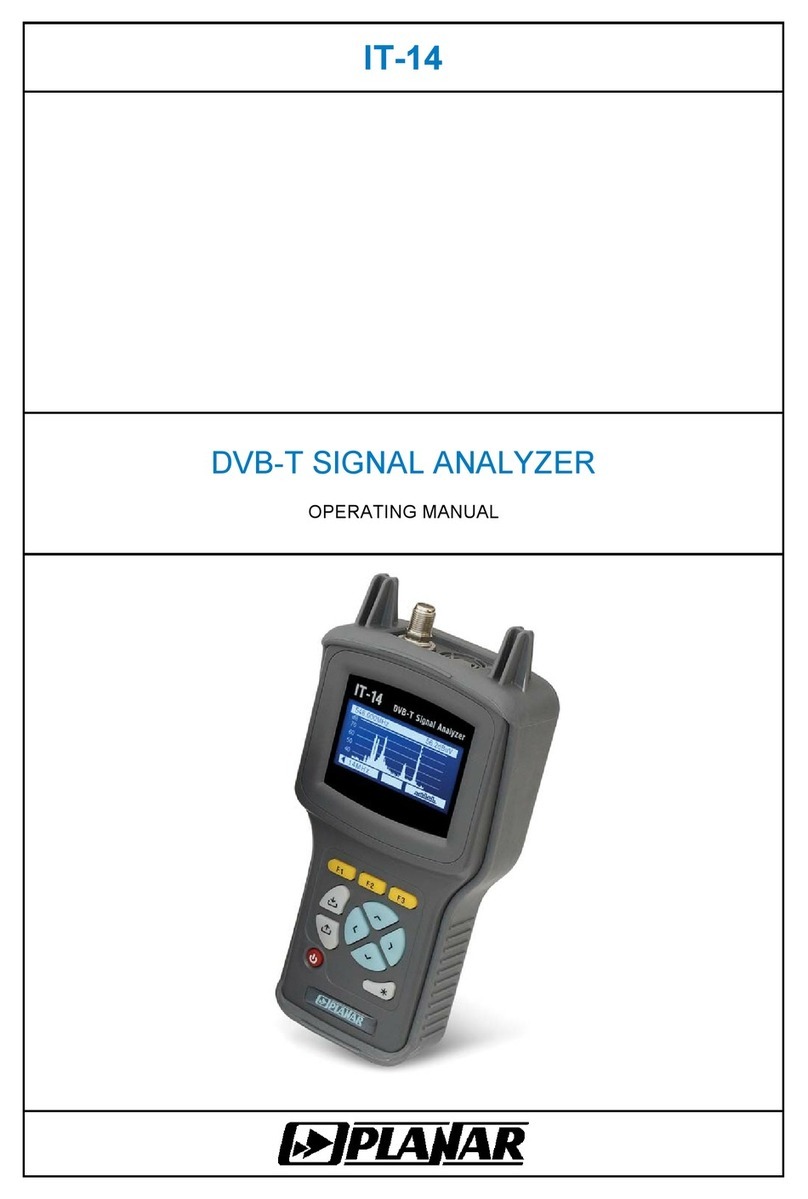
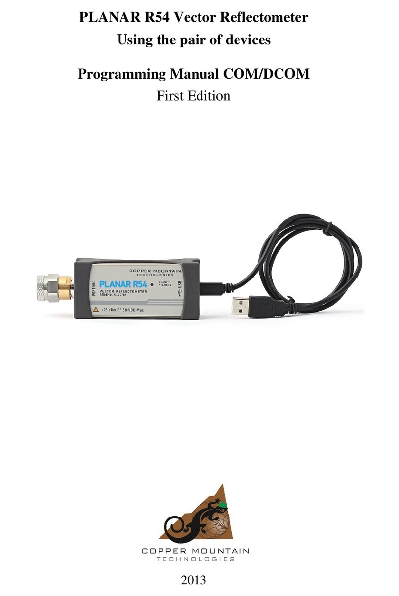
Planar IT-088 User manual

IT-088
DIGITAL DVB-T SIGNAL ANALYZER
OPERATING MANUAL

2
31.03.10

3
TABLE OF CONTENTS
1. PRODUCT FAMILY GENERAL INFORMATION.........................................................5
2. GENERAL DESCRIPTION AND PRINCIPLE OF OPERATION .................................6
2.1. INTRODUCTION............................................................................................................6
2.2. SAFETY PRECAUTIONS ................................................................................................6
2.3. FUNCTION ..................................................................................................................7
2.4. ENVIRONMENT CONDITIONS .........................................................................................7
2.5. PACKAGE CONTENTS ..................................................................................................8
2.6. DESIGN AND OPERATION OVERVIEW.............................................................................9
2.6.1. Principle of Operation.....................................................................................9
2.6.2. Block Diagram..............................................................................................10
2.6.3. Component Arrangement .............................................................................11
3. PREPARATION FOR OPERATION ..........................................................................11
4. OPERATION PROCEDURE .....................................................................................11
4.1. CONTROLS AND INDICATORS ......................................................................................11
4.2. PREPARATION FOR MEASUREMENTS...........................................................................12
4.3. MEASUREMENT PROCEDURE .....................................................................................15
4.3.1. General Information......................................................................................15
4.3.2. LEVEL Measurement Mode .........................................................................16
4.3.3. SPECTRUM Measurement Mode ...............................................................18
4.3.4. SCAN Measurement Mode .........................................................................18
4.3.5. TILT Measurement Mode ............................................................................19
4.3.6. RIPPLE Measurement Mode.......................................................................20
4.3.7. DVB-T/H TABLE Measurement Mode.........................................................20
4.3.8. DVB-T/H GRAPHIC Measurement Mode.....................................................23
4.3.9. DVB-T/H CONSTELLATION Measurement Mode .......................................25
4.3.10. Measurement Parameters Setting Mode....................................................27
4.4. DATA LOGGER FUNCTION ..........................................................................................28
4.4.1. General Information......................................................................................28
4.4.2. Channel Plan List .........................................................................................28
4.4.3. Channel Data Logger ...................................................................................32
4.4.4. Spectrum Data Logger .................................................................................36
4.5. MEMORY MANAGER ..................................................................................................38
4.5.1. General Information......................................................................................38
4.5.2. Operating the Memory Manager ..................................................................38
4.5.3. Testing the File Structure .............................................................................39
4.5.4. Determining the Memory Resources............................................................39
4.5.5. Viewing the Structure Table and Files of all Types ......................................39
4.5.6. Clearing the Memory....................................................................................40
4.6. SELF-TEST MODE .....................................................................................................41
4.6.1. General Information......................................................................................41
4.6.2. Removable Module Temperature.................................................................41
4.6.3. Battery Condition..........................................................................................41
4.6.4. Standby Battery Voltage...............................................................................42
4.6.5. Program Memory Check ..............................................................................42
4.6.6. Base Unit Check ..........................................................................................42
4.6.7. Removable Module Check ...........................................................................42
4.6.8. Data Logger NVRAM Check ........................................................................42
4.7. USER INTERFACE SETTING ........................................................................................42
4.7.1. General Information......................................................................................42
4.7.2. LCD Backlight Setting ..................................................................................43
4.7.3. LCD Contrast Setting ...................................................................................43
4.7.4. Audio Indication Volume Setting ..................................................................43

4
4.7.5. Audio Indication Switch ................................................................................43
4.7.6. Language Selection......................................................................................43
4.7.7. Reference Clock Frequency Setting.............................................................44
4.7.8. Reference Clock Date Setting ......................................................................44
4.7.9. Reference Clock Time Setting......................................................................44
4.7.10. Key Pressing Sound Selection ...................................................................44
4.7.11. Measurement Mode Quick Access.............................................................44
4.8. IDENTIFICATION DATA READOUT.................................................................................44
4.9. AUDIO INDICATION CHECK .........................................................................................45
4.10. OPERATION CONTROLLED BY PC .............................................................................45
4.10.1. General Information....................................................................................45
4.10.2. Configuration Requirements.......................................................................45
4.10.3. Software Installation...................................................................................46
4.10.4. Starting the Program ..................................................................................46
4.10.5. Program Main Window ...............................................................................47
4.10.6. Files Management......................................................................................48
4.10.7. Channel Diagram .......................................................................................49
4.10.8. Spectrum Analyzer.....................................................................................50
4.10.9. Digital Signal Measurement Mode..............................................................53
4.10.10. Data Logs Management ...........................................................................54
4.10.11. Channel Plan Management......................................................................58
4.10.12. TV System Editor .....................................................................................60
4.10.13. Report Viewing and Printout.....................................................................61
4.10.14. Program Settings......................................................................................61
4.10.15. Information Panel .....................................................................................63
4.11. SOFTWARE UPDATING .............................................................................................63
4.11.1. Software Updating via PC ..........................................................................63
4.11.2. Software Updating by means of MC-088 Removable Module....................65
4.11.3. Removable Module Software Memory Manager ........................................65
4.11.4. DVB-T/H Demodulator Software Updating .................................................66
4.12. BATTERY OPERATION ..............................................................................................66
5. MAINTENANCE ........................................................................................................67
6. TROUBLESHOOTING ..............................................................................................67
7. STORAGE.................................................................................................................68
8. TRANSPORTATION .................................................................................................68
9. LABELING.................................................................................................................68
10. WARRANTY INFORMATION..................................................................................68
11. APPENDIX ..............................................................................................................70
11.1. FREQUENCY TABLE FOR D/K STANDARD CHANNELS ..................................................70
11.2. FREQUENCY TABLE FOR B/G STANDARD CHANNELS..................................................73
11.3. FREQUENCY TABLE FOR M/N AIR STANDARD CHANNELS...........................................76
11.4. FREQUENCY TABLE FOR M/N CATV STANDARD CHANNELS .......................................79

5
1. PRODUCT FAMILY GENERAL INFORMATION
IT-08 is a multifunction handheld compact lightweight measurement instrument
incorporating two components. One of the components, MB-08 Base Unit, remains
invariable and provides display, control and powering (from batteries or mains adapter)
features. The other component, MC-08x, is one of the removable modules, which
determine measurement functions of the whole instrument.
IT-08 is capable to satisfy all your requirements in radio, cable and satellite, analogue
and digital TV measurements.
According to your measurement target, you can easily and quickly plug in one of the
modules into the Base Unit and perform the needed measurements. So, replacing the
modules you can obtain options featuring the following different applications:
IT-081 TV Level Meter (MC-081 module plugged-in), 5 to 900 MHz range.
Measurement of level, video-audio and carrier-noise ratios;
IT-082 Digital Satellite Meter (MC-082 module plugged-in), 950 to 2150 MHz range.
Measurement of BER and MER values for digital satellite (QPSK DVB-S). Powering LNB
SAT. DiSEqC generator;
IT-084 TDR Cable Reflectometer (MC-084 module plugged-in) for identification and
precision fault location in cables up to 1,600 m in length. Resolution 0.11 m;
IT-086 Optical Power Meter (MC-086 module plugged-in), measuring at –50 dBm to
+18 dBm range and wavelengths 1310 and 1550 nm.
IT-087 Digital TV QAM Signal Analyzer (MC-087 module plugged-in), 47 to 862 MHz
range. Support of DVB-C and ITU-T ANNEX A/C. Measurement of carrier level, C/N and
V/A ratios, channel power, MER, BER, and constellation diagram.
IT-088 Digital TV DVB-T Signal Analyzer (MC-088 module plugged-in), 47 to 862 MHz
range. Support of DVB-T and DVB-H with COFDM modulation. Measurements for analog
channels: carrier level, C/N and V/A ratios and for digital channels: channel power, MER,
BER, and constellation diagram.
Now we are pleased to offer you the six above modules, but the number is supposed to
grow in the nearest future. You can purchase MB-08 Base Unit accompanied by any of the
module(s), currently required, at your option. Later on, you can acquire any other
module(s) to expand your measurement abilities.
IT-08 GENERAL FEATURES (similar for all the IT-08 family instruments):
MB-08 dimensions (WxHxD) 90 x 200 x 55 mm
MC-08x dimensions (WxHxD) 60 x 70 x 27 mm
IT-08 weight 0.6 kg (including batteries)
keyboard made of rubber
display graphic LCD 128x64 pixels with backlight
power supply
internal NiMH AA rechargeable batteries, 2100 mAh (6 pcs)
external 12V/0.8A mains adapter
PC compatible interface RS-232 serial port
operating temperature −10 to +40 °C
user software update through serial interface from PC or the MC-08x
Removable Module

6
2. GENERAL DESCRIPTION AND PRINCIPLE OF OPERATION
2.1. Introduction
This Operating Manual is intended for introducing the design, functions, and basic
instructions related to operation and servicing of the IT-088 Digital DVB-T Signal Analyzer
(Analyzer).
The IT-088 is designed for control and adjustment of television and broadcasting
distribution networks as well as of separate components of such networks, or other
electronic devices. The Analyzer allows measurement of channel power and parameters of
TV signal with analogue and digital (DVB-T/H standard) modulation.
The Analyzer can be used both in laboratory, powered by an external power source,
and in field, powered by batteries.
The reliability of the IT-088 is ensured by fulfillment of regular maintenance procedures.
These procedures and their intervals are described in section 5.
In this manual the following abbreviations are used:
PC - Personal Computer
CD - Compact Disk
SW - Software
LCD - Liquid Crystal Display
FEC - Forward Error Correction
IF - Intermediate Frequency
HF - High Frequency
CDL - Channel Data Logger
SDL - Spectrum Data Logger
MER - Modulation Error Ratio
BER - Bit Error Rate
QPSK -Quadrature Amplitude Modulation
QAM - Quadrature Amplitude Modulation
COFDM - Coded Orthogonal Frequency Division Multiplexing
DVB-T - Digital Video Broadcasting – Terrestrial
DVB-H - Digital Video Broadcasting – Handheld
2.2. Safety Precautions
Thoroughly inspect the product and carefully read the related documentation to get
acquainted with all the safety markings and instructions before you start to operate the
Analyzer.
WARNING Only trained service personnel aware of the hazards involved
should perform repair on the Analyzer.
CAUTION Tuning the Analyzer and replacement of the components that
influence the accuracy of measurements without service personnel is
strictly prohibited, since the components used in the Analyzer are purpose-
made and their replacement will result in inaccurate operation of the
Analyzer. To exclude the possibility of mechanical damage to the IT-088,
the instructions regarding the storage and transportation (see sections 7
and 8) of the Analyzer must be observed.

7
2.3. Function
The IT-088 Digital TV DVB-T Signal Analyzer belongs to the family of IT-08
measurement instruments and is intended for measurement of the parameters of DVB-T
and DVB-H (hereinafter DVB-T/H) standard TV signal.
The Analyzer offers the following measurement modes for analog channels: video
carrier level, video carrier to audio carrier (V/A) ratio, and video carrier to noise (C/N) ratio.
For digital channels the measurement modes are the following: channel power and C/N
ratio. For DVB-T/H signals IT-088 offers measurement of reception quality parameters:
modulation error ratio MER, bit error ratio BER before and after Viterbi decoder, number of
error blocks after Reed-Solomon decoder, immunity margin MARGIN, and constellation
diagram. IT-088 features automatic defining of the settings of DVB-T/H signals (channel
frequency, number of subcarriers, guard interval, FEC, channel bandwidth, and modulation
type).
The IT-088 can be connected to a personal computer to access additional modes. The
IT-088 operates in spectrum analyzer mode displayed on the built-in LCD. The Analyzer
allows to measure direct and alternating voltage of the remote power supply of the TV and
broadcasting distribution networks.
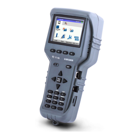
The appearance of the Analyzer and its components are displayed in figures 2.1 and
2.2.
Figure 2.1 Figure 2.2
This Operating Manual is made in accordance with the software version 8.0.0.2 for IT-
088.
2.4. Environment Conditions
Normal operating conditions:
a) ambient temperature (23±5)
0С;
b) relative air humidity (55±25)%;
c) atmospheric pressure 84-106 kPa (630-795 mm Hg);
d) voltage transients correspond to installation category CAT. II.
Rated operating conditions:
a) ambient temperature from -10 to 40 °С;
b) relative air humidity not greater than 90% at 25 ºСtemperature;
c) atmospheric pressure 84-106 kPa (630-795 mm Hg).

8
2.5. Package Contents
The Analyzer package includes:
a) MB-08 Base Unit............................. 1 pc.
b) MC-088 Removable Module ........... 1 pc.
c) Carrying Case ................................. 1 pc.
d) NiMH, AA Batteries ......................... 6 pcs
e) PS12/0.8 Mains Adapter ................. 1 pc.
f) “F”-”F” Adapter ................................ 1 pc.
g) RS-232 Data Transfer Cable........... 1 pc.
h) Rubber Holster................................ 1 pc.
i) Protective Bag................................. 1 pc.
j) Operating Manual ........................... 1 pc.
The Removable Module (if supplied separately) package includes:
a) МС-088 Removable Module .......... 1pc.
b) “F”-”F” Adapter ................................ 1pc.
c) Operating Manual ........................... 1pc.
Other optional accessories:
a) RS232-USB Adapter.
2.6 Specifications
Frequency tuning range: 5 to 900 MHz;
Operating frequency range: 45 to 865 MHz;
Resolution: 125 kHz;
Channel allocation standard: loaded from PC;
Input parameters:
a) input impedance within operating frequency range: 75 Ohm;
b) input impedance for frequencies up to 50 Hz: at least 200 kOhm.
Allowed resulting value of AC input voltage for frequencies over 5 MHz: 3 V.
Allowed resulting value of AC and DC input voltage for frequencies under 5
MHz: 150 V.
- Built-in attenuator: 20, 40 dB;
- Built-in amplifier (for digital channel measurements only) 11 dB;
- Input mismatch attenuation:
- Input attenuator and amplifier off: 14 dB;
- Input attenuator on: 18 dB;
- Level measurement range with manual attenuator setting:
- Input attenuator off 30 to 80 dBμV;
- Input attenuator 20 dB 50 to 100 dBμV;
- Input attenuator 40 dB 70 to 120 dBμV;
- Measurement level resolution: 0.1 dB;
- Accuracy within 30-120 dBµV level range: ±1.5 dB;
- Accuracy at operating temperature: ±2.2 dB;
- Measurement channel passband for -3 dB level: 230 ± 60 kHz;
- DVB-T/H demodulator parameters:
- Channel modulation: COFDM;
- Subcarrier modulation: QPSK, QAM16,
QAM64;
- Channel bandwidth: 8 MHz;
- Number of subcarriers: 2к, 4к, 8к;

9
- Guard interval: 1/32, 1/16, 1/8, 1/4;
- Hierarchical modulation: =1, =2, =4;
- FEC: 1/2, 2/3, 3/4, 5/6, 7/8;
- MER measurement range (QAM64, FEC=3/4): 18 to 35 dB;
- MER measurement resolution: 0.1 dB;
- MER measurement accuracy within the working range of
input signal power:
±2.0 dB;
- BER measurement range:
- BER before Viterbi decoder: 1,0x10-
2
to 1,0x10-
8
;
- BER after Viterbi decoder: 1,0x10-
3
to 1,0x10-
8
;
- DVB-T/H channel real power threshold (BER<2.0x10-
4
):
- QAM64, FEC=3/4, S/N=60 dB: 40 dBμV;
- Frequency auto tuning step: ±0.5 MHz;
- Frequency indication: 6 characters on LCD;
- Channel number indication: 3 characters on LCD;
- Signal level indication: 4 characters on LCD;
- Warm-up time: 10 min.;
- IT-088 can be powered by:
- AC circuit with 220 ± 22 V voltage, 50 ± 0.5 Hz
frequency with no more than 5% harmonic content, via
PS12/0.8 Mains Adapter;
- external DC source with 12 ± 0.6 V voltage, and no
more than 0.5 V ripple;
- batteries with capacity at least 2100 mAh;
- Current consumed from external power source or
batteries:
0.8 А;
- Continuous stable operation under normal conditions
(when powered by external source):
24 hrs;
- Battery duration under normal conditions (2100 mAh
battery capacity):
6 hours;
- Mean time between failures, no less than: 10000 hours;
- Average lifetime, no less than: 5 years;
- Dimensions: 200x90x55 mm;
- Package dimensions: 400x300ч90 mm;
- Weight: 0.6 kg;
- Weight in package: 2.2 kg.
2.6. Design and Operation Overview
2.6.1. Principle of Operation
The Digital DVB-T/H Signal Analyzer is a receiver of DVB-T/H signals with
demodulation of the traffic stream to MPEG-2. The input tuner is a super heterodyne
receiver with triple frequency conversion (auto or manual frequency tuning). Modulation
error ratio MER and constellation diagram are measured in the process of COFDM signal
demodulation based on vector analysis. Bit error rate BER in digital stream is determined
by means of analysis of Viterbi decoder operation (BER before the Viterbi decoder) and
Reed-Solomon decoder operation (BER after the Viterbi decoder). Channel power is
measured by means of analog-to-digital converter after signal peak detection at output of
logarithmic detector of the amplifier of the third IF. The principle of spectrum analyzer is
based on sequential analysis method with spectrum indication on the LCD of the Analyzer
or on PC.

10
The view displayed on the screen in DVB-T/H reception quality parameters
measurement mode is the numeric values and graphic representation of the measured
digital parameters (MER, BER before and after the Viterbi decoder, error bit counter after
Reed-Solomon decoder, and immunity margin). The constellation diagram mode shows
the vector structure of the quadrature components of the demodulated digital signal on the
phase plane. The spectrum analyzer mode shows the signal magnitude (signal frequency
bar-graph). The mode of signal level measurement in a frequency point displays the
numeric value of the signal level, V/A and C/N ratios.
2.6.2. Block Diagram
The block diagram of IT-088 is shown in figure 2.3.
Figure 2.3
After the Low-Pass Filter (LPF), the input signal if necessary is strengthened by the
Wide-Band Amplifier (WBA) or reduced by the two Attenuators (A1) and (A2). Then it is
transformed into the second IF signal by the Tuner (T). The WBA can be activated only for
digital channel measurements. The Tuner is the superheterodyne detector with double
frequency conversion. The first IF is 1220 MHz. In the signal level measurement mode the
second IF is 39 MHz, for digital channels demodulation the second IF is 36.125 MHz.
The signal of the second IF, after the Bandpass Filter (BPF1) and conversion in the
Mixer (M1) has the third IF, and further filtered at 10.7 MHz frequency by BPF3, which
determines the receiver frequency band.
Logarithmic Gain Amplifier Limiter (LGAL) performs logarithmation and signal detection.

11
Peak Detector (PD) allows measuring the video carrier level by means of Analogue-to-
Digital Converter (ADC). The digital code of the input signal peak level logarithm is defined
as real value and is corrected in accordance with the calibration matrix of the Control Unit
(CU) microcontroller.
In digital signal demodulation mode the signal with the second IF, after Bandpass Filter
(BPF2) filtering comes to DVB-T/H Demodulator (DD), which performs demodulation and
signal parameters measurement. The measured results are processed by the Control Unit.
The Control Unit receives the commands from the user entered via Keypad, processes
the data, displays them on the LCD, and also controls the operation with external PC.
The nonvolatile memory (NVRAM) stores the calibration coefficients set by the
manufacturer, Data Logger records, and firmware utilities.
The Power Supply (PS) forms the required voltages either from batteries or from an
external power source.
In the sound check unit the signal limited by FM is transmitted from the LGAL output to
Frequency Decoder (FD). Then the low frequency signal from the FD output is amplified in
the Low Frequency Amplifier (LFA) and goes to the built-in speaker.
2.6.3. Component Arrangement
The IT-088 is made up of two components. Both modules are contained within
plastic shockproof sectional housings that also include printed and three-dimensional
wiring. MB-08 Base Unit dimensions are 200x90x55 mm. MC-088 Removable Module with
70x57x26 mm dimensions is plugged in the Base Unit and connected to it via specific
connector.
The front panel of the Base Unit contains a keypad and a graphical display. The
right panel has a serial port connector, external power source connector and an on-off
switch. The Removable Module connector is located on the back panel. The Removable
Module has a 75-Ohm input “F” connector and the connector for connection to the Base
Unit.
3. PREPARATION FOR OPERATION
Perform external examination to make sure your IT-088 is free from any visible
mechanical damage.
Upon receipt of the package, check the availability of the items contained in it against
the list provided (see section 2.5).
If the IT-088 has been kept in the environment other than the rated operating
conditions, leave your Analyzer in facilities with normal operating conditions at least for 2
hours prior to operation.
4. OPERATION PROCEDURE
4.1. Controls and Indicators
The location of controls, indicators and connectors is shown in figures 2.1 and 2.2.
These elements have the following functions:
а) «F1», «F2», «F3», «F4» functional keys are intended for enabling the commands
corresponding to the icons shown on the screen of the IT-088;
b) «STD BY» key activates a single sweep in spectrum analyzer or bar-graph modes.
Lighting of the key indicates the power supply from an external power source;
c) « » double key controls the backlight of the screen;
d) «MENU/ENTER» key selects the current command or returns to the previous menu
level;
e) «», « », «◄», and «►» arrows allow editing the current operation mode;

12
f) alphanumeric keypad allows entering text or numeric data;
g) «ON/OFF» switch switches the power of the Analyzer on/off;
h) «12VDC» connector provides connection to an external power source;
I) «Serial Port» connector provides connection to computer;
j) «INPUT» connector is for the test signal input, “F”-type connector;
The controls are «F1», «F2», «F3», «F4», « », «◄», «►», « » and «MENU/ENTER»
keys.
Functional «Fx» keys are intended for selecting the command or mode of operation,
which is displayed in the bottom row of the screen above the corresponding key.
When operating in the main menu, « », « » keys select the rows containing the
icons corresponding to modes of operation to be selected.
For modes that contain parameters that can be edited one after another, « », « »
arrow keys are used for selecting a specific parameter.
« »,«◄»,«►»,« »keys are used for editing the parameters that can take a
number of different values.
«MENU/ENTER» key is used for quitting the mode and returning to a previous one,
or for entering text (e.g. entry name of the logs).
4.2. Preparation for Measurements
Before you start to operate your IT-088 make sure to carefully read this Operating
Manual as well as to inspect the location of the controls and indicators of the Analyzer (see
section 4.1).
To prepare your Analyzer for operation with the external power source proceed as
follows:
a) unlock the Carrying Case and take the Analyzer and the Mains Adapter out;
b) connect the MC-088 Removable Module to the MB-08 Base Unit, if they were
stored separately;
c) connect the Mains Adapter to the connector located on the side panel of the IT-088
and then to the power source;
d) set «On/Off» switch located on the right side panel to “On”.
To prepare your IT-088 for operation in stand-alone mode, powered by the batteries,
proceed as follows:
а) unlock the Carrying Case and take the IT-088 out;
b) connect the MC-088 Removable Module to MB-08 Base Unit, if they were stored
separately;
c) set «On/Off» switch located on the right side panel to “On”.
If the Removable Module software version differs from the software installed, then IT-
088 will start the program installation process automatically once the Analyzer is switched
on. The loading process is indicated by flashing backlight of the Analyzer screen.
CAUTION Do not switch the power off while the software is being loaded!
This may lead to the loss of capability of loading the software onto your
Analyzer without the use of a PC.

13
If the Removable Module software version does not differ from the software installed,
then the IT-088 starts to check the Removable Module after the power has been switched
on. The corresponding message will appear on the screen of the Analyzer. After
successful check, the following message (see figure 4.1) will appear on the screen:
Figure 4.1
The screen displays the name and type of the Analyzer. After approximately 1 second,
the Analyzer will switch to automatic testing mode.
If the Base Unit was previously operated with Removable Module of a different type,
then after first switching your IT-088 might start calibration matrices loading onto the Base
Unit. In this process the currently loaded matrix type will be indicated on the screen.
CAUTION Do not turn the power off during the process of loading! This
can lead to the incorrect loading of the calibration matrices and as a result
to high measurement error.
If the IT-088 operates correctly, the voltage of both main and stand-by batteries is
normal, and the temperature inside the Removable Module corresponds to the operating
conditions, then the message similar to that in figure 4.2 will appear on the screen. In case
any defect has been detected, one of the error messages described in section 4.6 will
appear.
Then the TV system table integrity check is activated. The table is stored in the
Removable Module, and a copy of it is stored in the Base Unit. The TV system table is
downloaded in the following cases: if the table and/or its copy are corrupted or the copy is
not available. If both the table and its copy are corrupted the Analyzer will download the
table of the OIRT TV system. While the download is in progress the screen will show TV
system loading message.
After the TV system table integrity check the main mode-selection menu (main menu)
will appear on the screen (see figure 4.3), or the last previously used measurement mode,
if you enable the quick access option (section 4.7.11).
Figure 4.2
To accelerate the procedure of turning the Analyzer on, press and hold
«MENU/ENTER» key, and set «On/Off» switch located on the side panel to “On” position.
The IT-088 will automatically display the main menu (figure 4.3). Release the key after
this. If the Analyzer previously was operating with a different Removable Module, then the
accelerated switching after changing the Module is not recommended. Follow the above
instructions.

14
To make sure that the Analyzer is operating properly perform the procedure described
below.
Select the icon in the main menu using « » and « » keys. Press «F2» key.
Select the row with the required parameter using « », «» arrows, and set the following
values by «◄»and «►»:
- Sound check: off
- Language: english or Sprache: deutsch or Язык: русский
- Click: type 1.
Press «MENU/ENTER». Test the functioning of the keypad by means of consecutive
pressing «1» … «9», «0», «С». Each pressing has to be accompanied with sound.
Select the icon at the bottom of the main menu screen using « » and « » keys
and press «F2». Select the required parameters using « », « » and then set the
following values using «◄»and «►»arrow keys:
Attenuator: autoselect
Map: off
Scan mode: 1:1
Averaging: average:1
Amplitude: auto
DVB-T scan: on.
Press «MENU/ENTER». Set the icon at the bottom of the main menu screen using
« » and «» arrows. Press «F4». Input signal spectrum will appear on the screen (figure
4.5). Set the scan start to 500 MHz by consecutive pressing of «5», «0», «0»,
«MENU/ENTER» keys. START=500MHz message will appear in the bottom line of the
screen.
Press «MENU/ENTER» key. Set the icon at the bottom of the main menu screen
using « » and «» arrows. Press «F1». The screen of the signal level measurement in
the frequency point will open (figure 4.4). Set the measured signal frequency to the video
carrier frequency of the 25 TV channel pressing «2», «5», «MENU/ENTER». The second
line will display the frequency value 503.250 MHz. The third line will show the channel
number Channel = 25. To return to the main menu press «MENU/ENTER» key.
Press «MENU/ENTER» key. Set the icon at the bottom of the main menu screen
using «»and «» arrows. Press «F1». Demodulator tuning message will appear on the
screen, and in several seconds the DVB-T/H demodulator will be activated. In case any
error has been detected during startup, the screen will show Tuning error message and
the Analyzer will return to the main menu (methods of error correction are given in section
6). After successful startup, DVB-T/H signal quality measurements in the form of a table
will appear on the screen (figure 4.9). Set the digital channel center frequency to the
center frequency of the s24 TV channel by pressing «c», «2», «4», «MENU/ENTER». The
first line will display the number of the channel s24, the second line will display the
frequency value 338.000 MHz. DVB-T/H demodulator synchronization status will be
indicated in the upper right corner of the screen. Before synchronization is achieved, its
progress bar is indicated as a series of dots. After synchronization is achieved, «LOCK»
message appear instead of the progress bar. If the channel level is too low, then «NO
SIG» message appears.
To return to the main menu press «MENU/ENTER» key.

15
4.3. Measurement Procedure
4.3.1. General Information
The IT-088 offers five functions of signal level measurement and three functions of
DVB-T/H signal reception quality.
a) measurement of signal level in the frequency point simultaneously with TV signal
parameters, as well as measuring alternating and direct power at the input of the Analyzer
in LEVEL measurement mode;
b) signal spectrum analysis in SPECTRUM mode;
c) TV signal parameter measurement in SCAN mode;
d) TV signal level tilt measurement in TILT mode;
e) TV signal level ripple measurement in RIPPLE mode;
f) DVB-T/H reception quality measurement with table representation in DVB-T/H
TABLE mode;
g) DVB-T/H reception quality measurement with graphic representation in DVB-T/H
GRAPHIC mode;
h) DVB-c reception quality measurement with constellation diagram in DVB-T/H
CONSTELLATION mode.
The c), d) and e) modes perform bar-graph measurements. To select the required mode
use arrow keys or functional keys.
Pressing « » and «» arrows in the main menu (figure 4.3) move the icon of the
required mode into the bottom line of the screen. The icons correspond to the modes as
follows:
a) LEVEL mode ;
b) SPECTRUM mode ;
c) SCAN mode ;
d) TILT mode ;
e) RIPPLE mode ;
f) DVB-T/H TABLE mode ;
g) DVB-T/H GRAPHIC mode ;
h) DVB-T/H CONSTELLATION mode .
Figure 4.3
To complete the selection of the mode press the functional key, which is under the
required icon. To return back to the main menu press «MENU/ENTER» key. If you are
selecting the mode with the active channel plan, first the following message will appear on
the screen:
Channel table name: with the name of the selected plan.

16
4.3.2. LEVEL Measurement Mode
The icon in the main menu refers to this mode. The signal level in the frequency
point is displayed on the screen in this mode. You can see the screen view in figure 4.4:
Index 1 is the signal level of the frequency, which value is marked by index 2.
Figure 4.4
Number of the channel containing the current frequency point is displayed in position
indexed 3. When operating by a channel plan you will see the name of the channel after its
number. Indexes 4 and 7 show the TV signal parameters: V/A and C/N ratios in the signal
spectrum. For the channels with digital modulation, DIGITAL will be indicated in position
indexed 4. Index 5 is a signal level represented as an indicator line along the dB scale.
Value of the direct or effective alternating voltage at the input (frequency 50 Hz of remote
cable power supply) is shown in position with index 6.
To measure the signal level in the required frequency point, set the frequency value by
«◄», «►» arrows. To select the channels use «», «» arrows. To enter the channel
number from the keypad, first press «F1». enter channel message will be for a short
moment displayed on the screen. To enter the number use the alphanumeric key set. To
enter special channels first press «C» key. After you have entered the number press
«MENU/ENTER». If the number is incorrect, after you pressed «MENU/ENTER» key the
previously saved channel number value will be restored. To enter the frequency value from
the keypad, first press «F2». enter frequency message will be for a short moment
displayed on the screen. To enter the frequency value in MHz use the alphanumeric
keypad. After you have entered the number, press «MENU/ENTER». If the frequency
value is incorrect, after you pressed «MENU/ENTER» key the previously saved value will
be restored. The frequency value will scroll from max to min with 0.125 MHz step. The
value being edited will be highlighted in inverse colour and flashing.
NOTE In “Channel plan operation” mode (4.3.7) pressing « » and « »
keys will scroll the channels of the plan. You can tune to any channel
entering its number by the alphanumeric keypad. If the channel does not
belong to the selected channel plan, its name will not be shown, only the
number of the channel will be indicated in position indexed 3.
The Ch= message and the channel number will be highlighted in inverse colour if the
frequency value does not match the following:
a) video carrier frequency (sound check disabled, no channel plan);
b) frequency point of the channel plan (sound check disabled, channel plan operation);
c) audio subcarrier frequency (sound check enabled).
If the tuning frequency does not fall within any channel frequency band, the number and
name of the channel will not be indicated.
Tuning to the channels and their numbering will be fulfilled in accordance with the
channel allocation standard (section 4.3.10).

17
Index 1 shows the measured level in dB related to 1 µV in the set point. To define V/A
and C/N ratios for analogue channels the IT-088 performs measurements in three
frequency points. The first one is the video carrier frequency (or the frequency your
Analyzer is set to). The second frequency point is the audio carrier frequency. The third
one is the point 0.5 MHz shifted down from the second one. V/A ratio will be indicated in
position indexed 4. C/N ratio will appear in position indexed 7.
The audio carrier frequency is defined in accordance with the frequency set by the
current TV system (TV system, section 4.3.10).
The IT-088 offers the capability of the frequency point selection for optimization of noise
measurements while operating by channel plan. (4.4.2.1).
For digital channels your Analyzer will perform measurements of two parameters: actual
channel power within the channel frequency band and the ratio of the digital TV signal to
the noise in the channel.
There are two methods of the actual channel power measurement. In the fast scan
mode (Scan mode: fast, section 4.3.10) power estimation is performed by one
measurement. The Analyzer will measure the channel power of the set frequency
(frequency value in the center of the channel) and then will calculate the actual channel
power according to the following formula:
Uac.dg = Um + 10*Lg (Bdg/Bm) + K, where
Uac.dg - actual channel power;
Um - measured channel power;
Bdg - digital channel frequency band;
Bm - frequency band of the measurement;
K - correction factor.
This method is fast and rather accurate only if the spectrum is almost uniform
throughout the channel band. If the spectrum variation is high this method can give big
error.
In the integration method the Analyzer will perform measurements of the power within
the entire channel band with 125 kHz step, and then calculate the average value, and
recalculate it into the actual power value.
This method is slower, but more accurate. It can be enabled in the Scan mode: 1:1
(section. 4.3.10).
To define the ratio of the digital TV signal to the noise in the channel your Analyzer will
measure the noise outside of the channel band. The noise frequency shift is determined by
the channel plan («Fnoise» parameter).
The C/N ratio An will be calculated by the following formula:
An = Um - Un, where
Um - measured channel power;
Un - noise power.
Digital channel parameters (central frequency, bandwidth, frequency shift for noise
measurement) should be taken from the channel plan. To increase the accuracy of the
measurement you should set the values either manually or in auto mode (section 4.4.2.1).
While performing measurements for digital channels it is recommended to apply the
mode of calculation for the maximum values: Averaging: average 8 (section 4.3.10). This
method ensures more accurate results for wideband noise-like signals.
The remote cable power supply voltage is measured from 10 to 100 V. The absolute
error of the measurement is lower than ±1.5 V. The measured value of the voltage at the
Analyzer's input is indicated in position indexed 6. If the voltage is direct you will see , if
the voltage is alternating you will see .

18
4.3.3. SPECTRUM Measurement Mode
The icon in the main menu refers to this mode. This mode displays the signal
spectrum. See figure 4.5 for the representation of the screen view:
Figure 4.5
Index 3 shows the signal level in the frequency point (value is displayed in index 1)
indicated by the marker (index 4). The marker is represented as a vertical dashed line. The
scan span limits by frequency are indicated in positions indexed 2 and 5.
You can navigate the marker by means of «◄»and «►» keys.
You can select any of the four parameters of the spectrum display by the functional
keys, and then set it by « » and «» keys.
To select the reference level press «F1». Ref.lev. = 0 dB message will appear on the
screen. Using «», «» arrows set the displayed level scale shift. If the automatic
selection mode of reference level is enabled (section 4.3.10), Auto mode message will
appear on the screen.
The level scale parameter is set by «F2» key. Scale = 10 dB/Div message will appear.
Use «», «» arrows to select the scale division from the available values 5, 10 and 20
dB/Div.
To set the scanning start press «F3» key. Start = 50 MHz message will appear. Use
« » and «» arrows to select the start of the sweep with 5 MHz step.
To set the frequency scale press «F4». Span = 2 MHz/Div message will appear. Using
«», «» arrows select the scale division from the available values 2, 4, 8, 16 MHz/Div.
The scanning span will be 14, 28, 56, 112 MHz correspondingly.
You can enter the scan start frequency using the alphanumeric keypad. After you have
set the frequency in MHz, press «MENU/ENTER». In case the new value is incorrect, the
previous value will be restored after you pressed «MENU/ENTER» key. To set scan start
frequency by channels, press «С» key and enter the channel number. Press
«MENU/ENTER» and the marker will move to the video carrier frequency point of the
selected channel.
If you select the frequency scale division greater than 2 MHz/Div, more than one
frequency point will be displayed in one column of the spectrogram, as the sweep step is
always 125 kHz. In this case the higher magnitude will be reported on the screen.
4.3.4. SCAN Measurement Mode
The icon in the main menu refers to this mode. This mode displays the signal
levels as a bar-graph. The screen view is presented in figure 4.6:
Figure 4.6

19
Index 1 shows the number of the channel indicated by the marker (index 4). The marker
is represented as a vertical dashed line. In case of a channel plan operation, the channel
name will be indicated after the number of the channel in index 1 (if the channel is
available in the channel plan).
Level value (index 3) and signal parameters (indexes 2 and 5) correspond to the
channel indicated by the marker.
You can navigate the marker by means of «◄»and «►» keys. You can enter the
channel number using the alphanumeric keypad. After you have entered the number,
press «MENU/ENTER».
In this mode you can adjust the magnitude scale parameters: scale division and shift.
Select the required parameter by «F1» or «F2» (section 4.3.3) and set the value by « »
and «» keys.
By pressing «F4» you can enable indication of the channel tuning frequency instead of
the name and number of the channel (index 1). To restore the view, press «F4» again.
When you operate with a channel plan, the scanning will be fulfilled only for the selected
channels. In this case the channel name will be displayed in the position indexed 1. The
channel name will be highlighted in inverse color if the frequency value does not match the
video carrier. You can shift the position of the marker by «◄»and «►» keys according to
the channels from the channel plan. You can set the marker to any channel using the
alphanumeric keypad, in this case the channel number will be displayed in position
indexed 1, and the parameters of the channel will be shown in positions indexed 2, 3 and
5.
If the channel in the channel plan is digital it will be described as DIGITAL (index 2),
and the measurements will be performed for the digital channel (section 4.3.2).
4.3.5. TILT Measurement Mode
The icon in the main menu refers to this mode. This mode displays signal levels
as vertical bars and the tilt line between the peaks of the two selected channels. The
screen view is represented in the figure 4.7:
Figure 4.7
Index 1 shows the channel number, indicated by the marker (index 5). The marker is
represented as a vertical dashed line. The reference marker (index 2) indicates the
channel number displayed in position indexed 4. The marker represents a triangle at the
top of the screen. Between the peaks of the selected channels the tilt line is displayed.
Index 3 shows the value of the difference between the selected channels.
You can navigate the marker by means of «◄»and «►» keys. You can enter the
marker location using the alphanumeric keypad. After you have entered the channel
number press «MENU/ENTER».
In this mode you can adjust the magnitude scale parameters: scale division and shift.
Select the required parameter by «F1» or «F2» (section 4.3.3) and set the value by « »
and «» keys. To set the location of the reference marker press «F3». Base marker
message will appear on the screen. Using « » and «» arrows set the reference marker
location.

20
By pressing «F4» you can enable indication of the channel tuning frequency instead of
the name and number of the channel (index 1). To restore the view, press «F4» again.
When you operate with a channel plan, the scanning will be fulfilled only for the selected
channels. You can shift the position of the marker by «◄»and «►» keys according to the
channels from the channel plan. Also you can set the marker to any channel using the
alphanumeric keypad.
4.3.6. RIPPLE Measurement Mode
The icon in the main menu refers to this mode. In this mode the screen displays
TV signal levels as vertical bars and two horizontal dotted lines between the peaks of the
two selected channels, which show the ripple. See figure 4.8:
Figure 4.8
Index 1 shows the channel number indicated by the marker (index 5), represented as a
vertical dashed line. The reference marker (index 2) indicates the channel number
displayed in position indexed 4. The marker represents a triangle at the top of the screen.
Between the peaks of the selected channels the ripple is displayed. Index 3 shows the
value of the difference between the selected channels.
You can navigate the marker by means of «◄»and «►» keys. You can enter the
marker location using the alphanumeric keypad. After you have entered the channel
number, press «MENU/ENTER».
In this mode you can adjust the magnitude scale parameters: scale division and shift.
Select the required parameter by «F1» or «F2» (section 4.3.3) and set the value by « »
and «» keys. To set the location of the reference marker press «F3». Base marker
message will appear on the screen. Use « » and «» arrows to set the reference marker
location.
By pressing «F4» you can enable indication of the channel tuning frequency instead of
the name and number of the channel (index 1). To restore the view, press «F4» again.
When you operate with a channel plan, the scanning will be fulfilled only for the selected
channels. You can shift the position of the marker by «◄»and «►» keys according to the
channels from the channel plan. Also you can set the marker to any channel using the
alphanumeric keypad.
4.3.7. DVB-T/H TABLE Measurement Mode
The icon in the main menu refers to this mode. Before measuring the
Demodulator tuning message will appear on the screen, and in several seconds the
DVB-T/H demodulator will be activated. In case any error has been detected during
startup, the screen will show Tuning error message and the Analyzer will return to the
main menu (methods of error correction are given in section 6). After successful startup,
DVB-T/H signal quality measurements in the form of a table will appear on the screen.
The main menu of the mode displays the table of the parameters featuring the input
DVB-T/H signal quality. The view of the screen is shown in figure 4.9:
Table of contents
Other Planar Measuring Instrument manuals