Planet Lighting Phantom User manual

PHANTOM
INSTALLATION MANUAL

1.0 INTRODUCTION
Please read this manual carefully before proceeding to correctly install the product, so as to protect
“the Service Personnel” and “the Operator” from any injury. The manual contains the drawings
relating to each installation task.
This appliance is a Class 1 medical device pursuant to AS/NZ standards 3200-2-41 (IEC 60601-2-
41) as amended and integrated and certies such conformity by axing the SAA marking.
CONFORMITY
The manufacturer declares that this Product is in compliance with AS/NZ standards 3200-2-41 (IEC
60601-2-41) as amended and integrated and certies such conformity by axing the SAA marking.
VALIDITY OF MANUAL
This installation manual is valid for the following models:
• Phantom - wall mount
• Phantom - ceiling mount
CUSTOMER SERVICE
The Planet Lighting after-sales service is at your disposal for any further details you might require
regarding the Product, its packaging, its transport and its installation and for any requests for techni-
cal and electrical diagrams:
Planet Lighting
12 Tamarind Drive
Bellingen NSW
2454
Australia
Ph: +61 2 6659 5600
F: +61 2 6655 2121
Email: info@planetlighting.com
COPYRIGHT
The reproduction and translation, including partial, of any of this manual is forbidden without written
permission from Planet Lighting..
TRANSLATIONS
The original language of this manual is English. For all other translations, reference must be made to
the original manual language.

1.1 GLOSSARY OF TERMS
TERM DEFINITION
PRODUCT THE EM (Electro-Medical) EQUIPMENT to which this manual
refers is the Planet Model ‘Phantom’ examination/Minor pro-
cedure light. For ease of description, in this manual this EM
EQUIPMENT will be called“Product”.
OPERATOR Person handling the equipment (e.g., professional health per-
sonnel, nonexpert person assisting the patient).
RESPONSIBLE ORGANIZA-
TION
Entity accountable for the use and maintenance of an EM
equipment or EM system (e.g., a hospital, an individual doctor
or a non-expert person). Preparation and training are included
in use.
SERVICE PERSONNEL Individuals or entities accountable to the responsible organisa-
tion that installs, assembles, maintains or repairs the equip-
ment. In certain circumstances, the safety of such persons
depends on their knowledge and training and ability to take
appropriate precautions when gaining access to hazardous
parts of The Product assembly. By way of example only, the
following professional gures are deemed as SERVICE PER-
SONNEL:
• Construction Engineer, Draftsman, Building rm duly regis-
tered in the professional Register, (for the masonry works)
• Electrical Engineer, or other Electro-technical expert quali-
ed to work as an electrician (for the electrical works)
For the installation phase, as regards assembly operations
only, a qualied person is deemed whosoever has attended a
course organised by Planet Lighting or, alternatively, whoso-
ever has carefully read the manual.

1.2 WARNINGS AND SAFETY NOTICES
WARNING This manual is an integral part of the Product as indicated by AS/NZ stan-
dards 3200-2-41 (IEC 60601-2-41 and subsequent amendments and
supplements. Read and keep this manual close to the Product.
WARNING The Product is not suitable for use in premises where explosion risks exist.
The Product is not suitable for use wherever there are inammable mixes of
anaesthetics with air, oxygen or N20 (laughing gas).
WARNING Planet Lighting disclaims all liability for any injury to persons or damage to
things caused by the Product having been installed by persons who are not
“SERVICE PERSONNEL”.
WARNING The RESPONSIBLE ORGANIZATION is entirely responsible for Product in-
stallation activities; no costs or responsibilities relating to the installation and/
or commissioning of the Product may therefore be traced back and/or in any
case attributed to Planet Lighting.
WARNING The ceiling or wall masonry works for Products to be installed on ceilings or
walls, and the electrical works for supplying power to the Product shall be
carried out in a workmanlike manner by SERVICE PERSONNEL to ensure
these are sturdy and safe.
WARNING The electrical system in the premises must conform to the applicable local-
standards, and any national regulations. A master switch must be installed
with fuse or thermal magnetic circuit breaker to be able to interrupt power to
the Product.
!DANGER – Electric shock risk
To avoid any risk of electric shocks, the Product must only be connected to
mains supplies with earth protection.

2.0 GENERAL INFORMATION
This installation manual describes how to install, maintain and operate the Planet Model ‘Phantom’
Examination/Minor procedure light (referred to throughout this document as the‘Product”). Prior to
installation carefully read through all the instructions enclosed in this manual.
The Phantom Light Complies with AS/NZ standards 3200-2-41 (IEC 60601-2-41)
2.1 PRODUCT DEFINITION
The Product is a state of the art Minor procedure/Examination light which utilises cutting-edge Solid
State Lighting technology. Designed and manufactured in Australia by Planet Lighting (established
1911) an R&D driven, exporting designer and manufacturer with over 10 years experience in the
design, manufacture and supply of Solid State Lighting devices worldwide.
The Planet Phantom provides an improved working environment, signicantly reducing ongoing
maintenance, with low operational costs and oers a “greener”alternative to similar products.
The Planet model Phantom allows the accurate positioning of the lamp head above any work sur-
face. It is designed to be mounted on a wall or ceiling and be pulled down from above when re-
quired, remaining there until repositioned.
At Planet we take great pride in the design and production of our lights and we are sure you will de-
rive satisfaction from owning and using our products. When installed and maintained in accordance
with the instructions contained in this service leaet, this product will provide many years of trouble-
free operation.
Should you have any enquiry, comment or special lighting need we would like to hear from you. We
back our products with pride, service and a ve year warranty.
Fig 1.0

2.1 OPERATOR QUALIFICATION
The following qualication requirements are based on the denitions given under the ‘Glossary of
Terms ‘ section on page 3. The qualication requirements for various tasks relating to the Product are
as follows :
Installation: SERVICE PERSONNEL
Use: OPERATOR
Cleaning: OPERATOR
Routine maintenance: SERVICE PERSONNEL
Special maintenance: SERVICE PERSONNEL
Disposal: RESPONSIBLE ORGANISATION and SERVICE PERSONNEL
2.2 ENVIRONMENTAL CONSIDERATIONS
2.2.1 PACKAGING
Cardboard boxes containing Product. Dispose of these in compliance with national directives appli-
cable for waste disposal.
2.2.2 TRANSPORT
Product transport is done by land, sea or air according to the following characteristics:
Temperature (°C): -15 / +60
Humidity: 10 / 75 %
Atmospheric pressure (hPa): 500 / 1060
2.2.3 STORAGE
The packaged Product must be stored (warehoused) in dry premises having the following character-
istics:
Temperature (°C): -15 / +60
Humidity: 10 / 75 %
Atmospheric pressure (hPa): 500 / 1060
2.2.4 PLACE OF INSTALLATION
The premises where the product is started up must have the following characteristics:
Temperature (°C): +10 / +40
Humidity: 30 / 75 %
Atmospheric pressure (hPa): 700 / 1060
2.2.5 RECYCLING
Design of the Product takes into account the materials used in the manufacture of components.
This is to ensure when it reaches its end of life, the disposal method with the lowest or least negative
impact, on human health and the environment is selected.
Unlike the sources of traditional light, LED’s do not contain mercury, toxic gases, laments or fragile
parts. Due to the xture being over 95% recyclable and there being no Bulbs/Globe changing during
the ULED life of 50,000+ hours, your environmental footprint will be signicantly reduced.
When your Product reaches the end of its life, contact Planet lighting or our local agents to learn
about recycling options. The Phantom light must be disposed of properly according to local laws
and, regulations.
2.3 GRAPHIC SIGNS AND SYMBOLS USED IN THE INSTALLATION MAN
UAL
The following safety measures must be put in place during Product installation, use and servicing.
To emphasize their importance, a number of safety precautions are repeated throughout the manual.
Follow the safety precautions before using or repairing the Product. Carefully abiding by the safety
precautions improves the ability to use the Product safely and correctly and helps prevent incorrect
maintenance which could be hazardous and cause damage. The safety measures are

approximate and not exhaustive; the Operator, the Responsible Organization and the Service Per-
sonnel must develop their capacities to upgrade and integrate them.
Indications such as DANGER, WARNING and CAUTION, preceded by the symbol !indicate
the level of risk to which the SERVICE PERSONNEL, the RESPONSIBLE ORGANIZATION and the
PRODUCT could be exposed.
DANGER: indicates an immediately hazardous situation which could result in death or serious inju-
ries.
WARNING: indicates a potentially hazardous situation that could result in death or serious injuries.
CAUTION: indicates a potentially hazardous situation which could result in moderate or light injuries
and Product damage.
This triangular symbol together with the explanation alongside (shown above) indicates the
type of hazard to be dealt with.
2.4 GRAPHIC SYMBOLS USED ON PACKAGING
The following table lists the common symbols used by planet lighting on our packaging.
DESIGNATION SYMBOL DESCRIPTION
THIS SIDE UP Package must always be transported, handled and stored
with the arrows always pointing upwards.
FRAGILE The cargo is easily broken or damaged. Cargoes marked
with this symbol should be handled carefully and should
never be tipped over or slung.
TW0 PERSON LIFT Cargo with this symbol weighs in excess of 20kg. For per-
sonal safety these items should only be lifted mechanically,
or by two or more people.
!

2.5 GRAPHIC SYMBOLS USED ON THE PRODUCT
Below are the symbols to be found on the Product:
DESIGNATION SYMBOL DESCRIPTION
POSITIVE
+VE
Connect positive wire here
NEGATIVE
VE
Connect negative wire here.
ACTIVE/LIVE
L
Connect active/live wire here
NEUTRAL
N
Connect neutral wire here
EARTH Connect earth wire here
DATE OF MANUFAC
TURE
Date of manufacture (Month/Year)
MANUFACTURER Manufacturers address
READ OPERATING
MANUAL
Compulsory to read the operating manual
2.6 WARRANTY AND LIABILITIES
Planet Lighting disclaims all liability with regard to unreliable Product operation in the following cases:
• Installation, authorised modications and repairs have not been performed by SERVICE PER-
SONNEL
• The Product has not been used for its intended purpose and in conformity with the operating
instructions (see operation manual).
• The premises have not been approved for healthcare activities
• The premises are not built in conformity with the law and applicable regulations
• The electrical system in the premises is not in compliance with appropriate requirements
2.7 STRUCTURAL CHANGES OR VARIATIONS
No arbitrary structural changes or variations to the Product are admitted. Any modications must
have the prior written authorisation of Planet Lighting. In case of the Product having been tampered
with, the warranty shall be invalidated and the manufacturer disclaims all liability for any injuries or
damage caused to the OPERATOR, the RESPONSIBLE ORGANIZATION and the SERVICE PER-
SONNEL.
3.0 PLANNING
3.1 PREPARING THE PREMISES STRUCTURALLY

!WARNING SAFE MASONRY WORKS
The masonry works for preparing the ceiling to install the Product must be sturdy and safe and com-
pleted in a workmanlike manner, according to applicable building regulations.
By way of example only, the professional persons charged with completing the masonry works could
be: Construction Engineer, Structural engineer, or a Builder, duly registered in the respective profes-
sional register.
!DANGER WRONG WALL PERFORATION
In case of wrong perforation of the Product supporting wall (e.g., the breakage of a reinforced-
concrete ceiling/wall iron) always inform the building manager as this could aect the stability of the
building.
!WARNING CEILING AND WALL STRUCTURAL CAPACITY
The ceiling must be able to withstand a weight of at least 300 kg/m2 and have a thickness of at least
250 mm. For the wall version, the wall must be a supporting wall and be made of solid brick. Installa-
tion on walls of perforated bricks and plasterboard is only allowed with the tting of another plate on
the opposite side of the wall (sandwich closing).
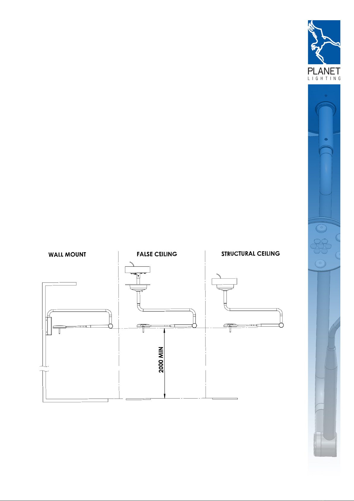
Following are the structural loadings and approx product weights. The listed weights and loads are
static only, and as such do not include any dynamic loads or externally applied loads such as opera-
tor handling. For similar detail, you may also refer to Fig 2.0 for Ceiling, and Fig 15.0 for Wall mount-
ed versions:
Structural capacity requirements - Ceiling Mounted
Total Mass - structural ceiling tting only: 10.6kg
Mass - arm only: 6.3kg
Torque (at mounting plate): 63Nm
Structural capacity requirements - Wall Mounted
Total Mass - structural ceiling tting only: 10.22kg
Mass - arm only: 6.3kg
Torque (at mounting plate): 69Nm
The Product installation premises must conform to local building standards.
After making sure the premises used for medical purposes are in conformity with the above require-
ments, proceed to mechanically anchor the ceiling and wall plate, assessing the type of building and
making all consequent adaptations.
THE SERVICE PERSONNEL have all technical, civil and legal responsibilities relating to correctly and
suitably performing Product anchoring and installation operations in an adequate manner.
3.2 CORRECTLY WIRING UP THE PREMISES
DANGER SAFE WIRING INSTALLATIONS
The premises used for medical purposes must be safely wired up in a workmanlike manner by SER-
VICE PERSONNEL to power the Product.
DANGER ELECTRICAL ENVIRONMENT IN COMPLIANCE WITH THE LAW
Before installing the Product, the SERVICE PERSONNEL must make sure
the following conditions exist:
• The wiring system of the environment (premises) in which installation is made must conform with
regulations for premises used for medical purposes and with applicable national laws and/or
regulations.
• The electrical system must have a certicate of conformity issued by whosoever installed it.
• The earth system must be certied as required by applicable regulations.

4.0 INSTALLATION
The Planet Model Phantom arm is designed to be mounted above the immediate work area. Stan-
dard mounting xtures for Planet Model Phantom are: Ceiling Mount & Wall Mount (specialised
mountings are available on application). In all cases the suggested mounting height (measured at
swivel head) is two metres from oor level, as seen in Fig 1.0.
4.1 CEILING MOUNT
!
WARNING
The qualied electrician who is responsible for the installation of the Phantom must include an isola-
tion switch( all -pole disconnection) in the xed wiring of the Phantom and a cable tie near the termi-
nal block of the primary(240V) wiring (Phase and Neutral) to secure the cables.
STRUCTURAL LOADS CEILING MOUNT:
The structural integrity of the mounting surface is the responsability of the installer. Structural loads
are as follows:
Fig. 2.0
4.1.1 MOUNT CEILING PLATE AND LEVEL
Use the Ceiling Template (found in the centre of this document) to mark out the hole locations for the
ceiling plate.
Fig. 3.0
1. Installer must ensure sucient structural integrity of the mounting surface (Refer to 3.1).
2. Fix the ceiling plate to the structural ceiling using suitable xings (to be selected by the installer).
3. It is very important that the installer ensures the mounting plate and collar are level. This will ensure

that the centre axis of the mounting collar is plumb, and the light is balanced.
NOTE: If ceiling tube is the pre-welded type, please go to section 4.1.5
4.1.2 DETERMINE THE CEILING TUBE LENGTH
Fig. 4.0
4.1.3 CUT CEILING TUBE TO LENGTH
!
WARNING
Do not cut tube end with countersunk holes
Fig. 5.0
4. Cut ceiling tube to length, based on the table in Fig. 4.0
5. Measure, and drill 10mm through-hole for the locking bolt, as shown in Fig. 5.0.

!
4.1.4 PRE CEILING FIT OUT
6. Assemble ceiling tube to ceiling plate, with the locking bolt and nut, as shown in Fig. 6.0
7. Reticulate 240V power to the power supply mounting location in accordance with local standards
and regulations. Attach the mounting plate earth, and reticulate power to the mounting location, as
shown in Fig 7.0.
4.1.5 RETICULATE POWER TO CEILING LEVEL
8. Drill cable access hole in the ceiling tube at the sub-ceiling level, as shown in Fig. 8.0. Take care to
remove power cords from the drilling area, before drilling.
9. Complete the reticulation of 24V power to the power supply mounting location as shown in Fig 9.0.
Fig. 6.0 Fig. 7.0
Fig. 8.0 Fig. 9.0

4.1.6 POSITION POWER SUPPLY AND TIGHTEN ONTO THE CEILING TUBE
Fig. 10.0
10. Slide power supply into mounting position, as close to the ceiling as possible, as shown in Fig.
10.0.
11. Using the u-bolt, nuts and washers supplied, attach the power supply assembly to the ceiling
tube, as shown in Fig. 10.0.
4.1.7 CONNECT POWER
24V DC OUTPUT TERMINAL.
THIS IS THE MAIN OUTPUT
FOR THE LIGHT FITTING
GEAR TRAY CLAMP
FIXES THE GEAR TRAY
TO THE CEILING TUBE
240V AC INPUT
TERMINAL
240V INPUT
TO DRIVER
MEANWELL
RPS-60-24 24V
DC POWER
SUPPLY
24V DC OUTPUT
24V DC OUTPUT
FOR THE LED
INDICATOR LIGHT
12
13
Fig. 11.0
12. Connect the 24V power feed, and earth for the light tting into the terminal, shown in Fig. 11.0
13. Connect the 240V AC input, and earth into the terminal, as shown in Fig. 11.0.

4.1.8 ATTACH CEILING COVER
14. Move ceiling cover into place, and connect the 24V DC output for the LED indicator light.
15. Push the ceiling cover up against the ceiling and tighten the grub screw to lock it in place, as
shown in Fig.13.0.
4.1.9 ATTACH LIGHT FITTING TO CEILING TUBE
Fig. 14.0
16. Lift Phantom arm into place, and engage the 24V plugs as shown in Fig. 14.0.
17. Insert the arm bearing into the ceiling tube (taking care to align the threaded holes on the bearing
sheath with the countersunk holes on the ceiling tube), as shown in Fig. 14.0.
18. Insert the countersunk-head set screws as shown in Fig. 14.0.
19. Optional - remove or replace the lamp head - twist the conical end of the arm and pull the head
Fig. 12.0 Fig. 13.0

and s-bend section, as shown in Fig.14.0.
MAINTENANCE ONLY
20. Unscrew the end cap for access to the spring balance adjustment, as shown in Fig. 14.0.
21. Adjust the spring balance: using a 4mm allen key, adjust the screw inside the knuckle. Clock-
wise/Tightening the screw will cause heavier engagement of the spring - this will improve‘head
droop’. Anticlockwise/loosening the spring balance will x a ‘rising head’ issue, as shown in Fig.
14.0.
22. Friction adjustment: Clockwise/tightening this screw will apply more friction to the arm mecha-
nisms. The arm will require more force to move, and will not move as far with the momentum of an
individual movement. This should be set to the sta preference, as shown in Fig 14.0.
4.2 WALL MOUNT
STRUCTURAL LOADS WALL MOUNT:
The structural integrity of the mounting surface is the responsibility of the installer. Structural loads
are as follows:
Fig. 15.0
4.2.1 MARK UP AND MOUNT WALL UNIT
1. Use the wall mount template from the centre page of this document. Measure up 1907mm from
the oor, and align the bottom of the wall mount template with this mark. Position and x the tem-
plate into position, ensuring that both edges are level to the vertical and horizontal, as shown in Fig.
16.0. Use the template to mark hole positions for cable access and mounting.
2. Installer to select suitable xings, and x the wall unit to the structurally sound wall, ensuring that
the unit is level on all edges Fig. 17.0.
3. Reticulate the 240v power to the power supply location, and connect to the tting at the terminal
block as shown in Fig. 17.0.
Fig. 17.0
Fig. 16.0

4.2.3 MOUNT FITTING
Fig. 18.0
4. Lift Phantom arm into place, and engage the 24V plugs as shown in Fig. 18.0.
5. Insert the arm bearing into the wall unit (taking care to align the threaded holes on the arm side
bearing sheath with the corresponding holes on the bearing sheath on the wall unit, as shown in Fig.
18.0.
6. Insert and tighten the two grub screws to complete the xing of the arm to the wall unit as shown
in Fig.18.0.
7. Replace the wall unit cover as shown in Fig. 18.0.
8. Fix in place with the countersunk screws provided, as shown in Fig. 18.0.
MAINTENANCE ONLY
9. Unscrew the end cap for access to the spring balance adjustment, as shown in Fig. 18.0.
10. Adjust the spring balance: using a 4mm allen key, adjust the screw inside the knuckle. Clock-
wise/Tightening the screw will cause heavier engagement of the spring - this will improve‘head
droop’. Anticlockwise/loosening the spring balance will x a ‘rising head’ issue, as shown in Fig 18.0.
11. Friction adjustment: Clockwise/tightening this screw will apply more friction to the arm mecha-
nisms, as shown in Fig. 18.0. The arm will require more force to move, however will not continue to
move with moment. This should be set to the sta preference.

5.0 OPERATING INSTRUCTIONS
5.1 GENERAL OPERATION
The general operation sequence is as follows:
1. Switch light on
2. Adjust dimming as required
3. Using the handle, position the head of the tting and direct the light at the target location
4. Perform task
5. Reposition for other tasks if required
6. Turn light o after use
!
WARNING: Take care that you DO NOT direct the lighting beam into your eye’s (or any-
one elses) during operation. Looking directly into this light could cause permanent eye dam-
age.
5.1 SWITCH AND DIMMING OPERATION
The Products lighting functions are controlled via the use of the membrane switch located on the
head of the tting, on the opposite side to the handle. The controls (shown below) oer a simple on/
o switch and an additional up/down dimming control. The dimming control allows the user to set
the brightness level of all LED’s in the head together.
POWER - ON/OFF DIM - DOWN DIM - UP

6.0 MAINTENANCE
6.1 MAINTENANCE TASK SCHEDULE
The following periodic maintenance task are recommended for both the Wall, and Ceiling mounted
Products:
TASK DESCRIPTION FREQUENCY
sterilise handle Remove handle (as per instructions below),
and place in an autoclave (or similar sterili-
sation machine) for sterilisation.
Once per use
clean/disinfect
Product
Using a suitable disinfectant, wipe down all
exterior surfaces of the tting.
1 per day
Adjust balance
and friction
Adjust the spring tension and friction set-
tings as per instructions in 4.2.3 items 9-11.
1 per 3-12
months (site spe-
cic)
6.1 MAINTENANCE TASK DEFINITION
6.1.1 STERILISE HANDLE
To sterilise the handle:
1. Remove the handle from the tting (see Fig. 19.0 below).
2. Place handle in the autoclave (or similar sterilisation. machine), and run the cleaning cycle. Make
sure that you consult the operating instructions for the sterilisation machine.
3. Re-attach the handle to the light tting (see Fig. 19.0 below).
1. SQUEEZE HANDLE
TO DISENGAGE THE
LOCK MECHANISM.
2. REMOVE/ATTACH
Fig. 19.0
!
CAUTION: Heat treated sterilisation processes will result in the handle being quite hot,
and may result in burns. Ensure that these handles have cooled to room temperature before
re-attaching them to the lights.

6.1.2 CLEANING AND DISINFECTING
!
WARNING: Turn o the light before commencing any cleaning.
Please use the following procedures and precautions during the cleaning process:
• Let the light cool down. Disinfect and clean the light and body (including any cables) only when it
is cold.
• Make sure that excess water/cleaning agent has been removed from cleaning cloth before com-
mencing.
• Use a damp, NOT wet Cloth.
• Use alcohol/detergent having medium alkaline level but no active chlorine.
!
CAUTION: Do not use abrasive products, petrol, paint thinners, alkaline detergent,
acidic cleaning agents or aldehydes. Make sure the proportions of the detergents/cleaning
agents are accurate based on manufacturers instructions.
.
!
WARNING: The disinfectants/cleaning agents may contain substances harmful to health:
use disinfectants only recommended by your health authorities and follow the manufacturer’s
user instruction carefully.
!
CAUTION: DO NOT spray cleaning solutions directly onto the Product as it may aect
product life and performance. Spray onto a cloth and wipe the product.( See Fig. 20)
Fig. 20.0
Made in Australia Exported to the World
Tamarind Drive Bellingen NSW 2454 Australia
Phone + 61 (0)2 6659 5600 Fax + 61 (0)2 66552121
info@planetlighting.com www.planetlighting.com
Customer Service can be contacted on the phone number below
Mon - Friday 9 am - 5 pm
Table of contents
Other Planet Lighting Medical Equipment manuals
Popular Medical Equipment manuals by other brands

EASTMAN
EASTMAN Kodak X-Omat 1000 installation instructions

DeVilbiss
DeVilbiss iFill 535D Instruction guide

Karl Storz
Karl Storz DUOMAT instruction manual

Dexcowin
Dexcowin iRayA6s user manual

Verathon
Verathon BLADDERSCAN PRIME Operation & maintenance manual

Halyard
Halyard COOLIEF SINERGY Instructions for use