Planet Lighting ULED Installation and operating instructions

Model ‘ULED’ Spring Balanced Examination Light - Installation & Maintenance Instructions
1.0 INTRODUCTION
This installation and instruction manual describes how to install, maintain and operate the Planet Model
‘ULED’ examination light. Prior to installation carefully read through all the instructions enclosed in this
manual.
If there are any concerns or you do not understand, please contact customer service at Planet Lighting.
WARNINGS
Only qualified electricians can install the Planet model ‘ULED’ light. It is to be direct wired only. Installation
performed by unauthorised personnel could result in personal injury and or equipment damage. Under
no circumstances should any modifications or adjustments, other than those detailed under section 9.0
Maintenance, be made to the Planet Model ULED.
2.0 Product Information
The Planet ULED is a state of the art examination light which utilises cutting edge Solid State Lighting technology
combined with the proven Planet Model U spring arm and bracket system. Designed and manufactured in Australia by
Planet Lighting (established 1911) an R&D driven, exporting designer and manufacturer with over 6 years experience
in the design, manufacture and supply of Solid State Lighting devices worldwide.
The Planet ULED provides an improved working environment, significantly reducing on-going maintenance,
with low operational costs and offers a “greener” alternative to similar products.
The Planet model ULED allows the accurate positioning of the lamp head above any work surface. It is designed to be
mounted on a wall or ceiling and be pulled down from above when required, remaining there until re - positioned.
At Planet we take great pride in the design and production of our lights and we are sure you will derive satisfaction
from owning and using our products. When installed and maintained in accordance with the instructions contained in
this service leaflet, this product will provide many years of trouble free operation.
Should you have any enquiry, comment or special lighting need we would like to hear from you. We back our products
with pride, service and a five year warranty.
2.1.0 Environmental Considerations
2.1.1 Packaging
I box containing a complete ULED lamp with Installation and users manual.
2.1.2 Transport
transport to be carried out by road, while maintaining the following environmental conditions.
Temperature: -15/+60 degrees Celsius
Humidity : 10/75%
Atmospheric pressure(h/Pa) 500/1060
2.1.3 Storage
The devices packaged must be stored (warehoused) in a dry place and as per the same
environmental conditions mentioned above.
2.2.0 Disposal and Recycling Information
The ULED light has been designed, taking into account what the manufacturing components are
made out of. This is to ensure when it reaches its end of life, the disposal method
with the lowest/ least negative impact, on human health and the environment is selected.
Unlike the sources of traditional light, LED’s do not contain mercury, toxic gases, filaments or
fragile parts. Due to the fixture being over 95% recyclable and there being no Bulbs/
Globe changing during the ULED life of 50,000+ hours your environmental footprint will be
significantly reduced.
When your ULED light reaches its end of life, contact Planet lighting or our local agents to learn
about recycling options.The ULED light must be disposed of properly according to local laws and,
regulations.
3.0 PLANNING
Prior to installing the Planet Model ‘ULED’ Ceiling and Wall mounts the following items should be checked and con-
firmed.
3.1.0 Architectural considerations
3.1.1 Ensure appropriate mounting structure behind the wall/ceiling
3.1.2 For structural loadings and appox product weights (refer Fig12)
3.1.3 To confirm ceiling/wall height measurements at the appropriate nominal recommended
height from the floor refer Fig 1 (back page)
3.2.0 Electrical considerations
3.2.1 The Planet Model ‘ULED’ wall and ceiling mount are designed to be direct wired only
3.2.2 240V AC supply is available at the connection points
Made in Australia Exported to the World
Tamarind Drive Bellingen NSW 2454 Australia
Phone + 61 (0)2 6659 5600 Fax + 61 (0)2 66552121
[email protected] www.planetlighting.com
Customer Service can be contacted on the phone number below Mon - Friday 9 am - 5 pm
Fig: 12
Recommended
height: 2000 mm
to bottom of lamp pivot
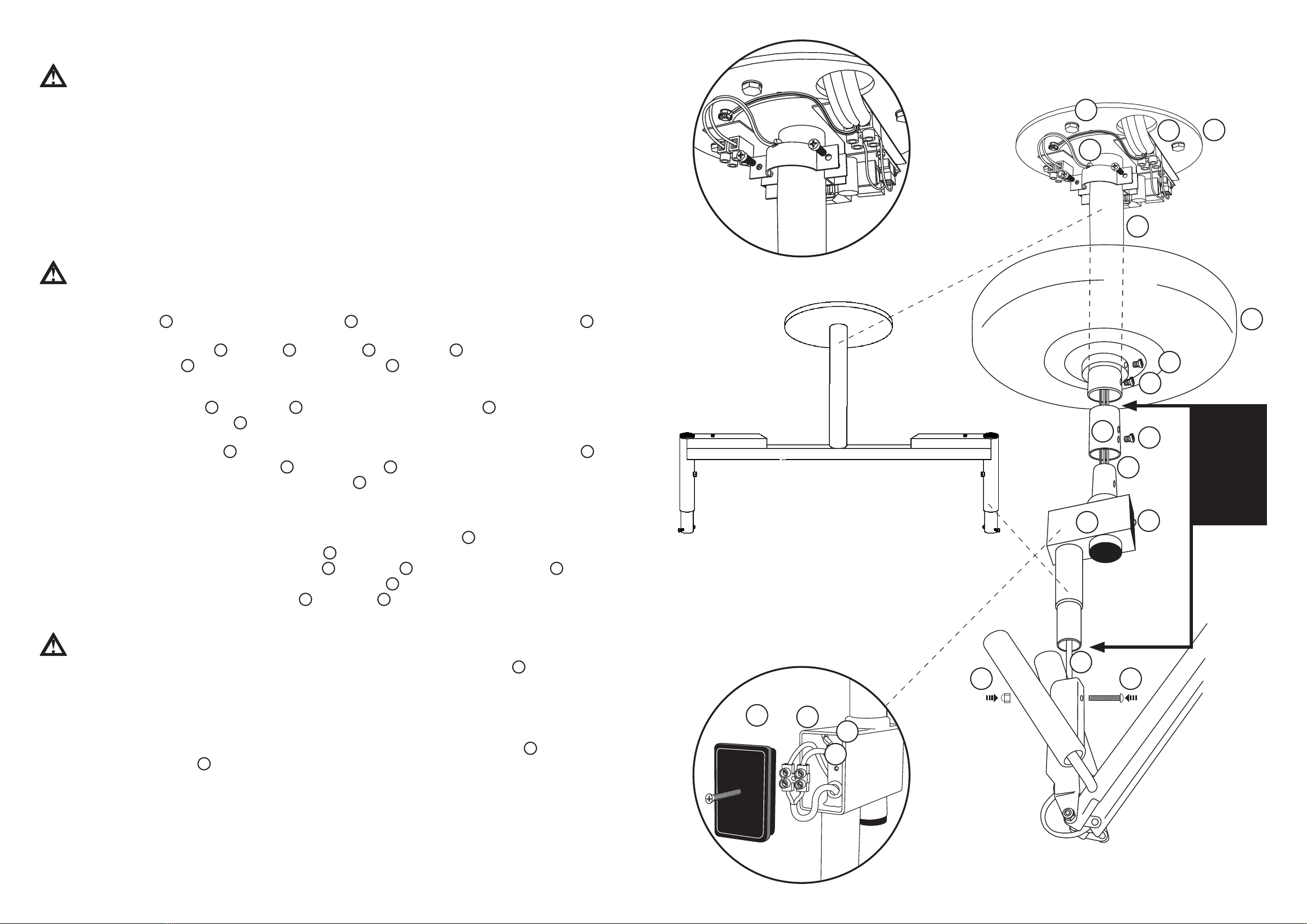
Standard ceiling fix Suspended ceiling fix
Structural ceiling
Recommended
height: 2055 mm
to bottom of
mounting plate
Wall fix
Fig: 1
Recommended
height: 2000 mm
to bottom of swivel head
Ensure
level
Ensure
level
Recommended
height: 2055 mm
to bottom of
mounting plate
610 NOM (= ~16 Nm)
445 NOM (= ~12 Nm)
RELATIVE VERTICAL
MASS: 2.7kg
POSITION SHOWN HERE
IS ESTIMATE ON LY.
(ARM+HEAD ONLY)
Note:
For the purposes of quoting minimum structural requirements of mountings, torque-load of 12 Newton Metres
plus lever-arm effect of length of ceiling-mount tube or wall mounting must be accommodated (plus factors
of safety and dynamic loads). Vertical dead load (IE No dynamic or external loads such as operators pulling or
pushing fitting are included in this value.)
Static weights of complete fixture (Mount, Arm & Light Head)
Wall Mount - 5.5kg
Ceiling Mount - 6.0kg

4.0 INSTALLATION:
The Planet Model ULED arm is designed to be mounted above the immediate work area. Standard mounting fixtures for Planet Model ULED are:
Ceiling Mount & Wall Mount (specialised mountings are available on application). In all cases the suggested mounting height (measured at swivel
head) is two metres from floor level. (refer Fig 1)
To ensure correct balance of the Model ULED movement the lamp must be mounted with the stem, around which it rotates, vertical at all
times.
(refer Fig 1)
WARNING The qualified electrician who is responsible for the installation of the ULED must include an isolation switch( all -pole discon-
nection ) in the fixed wiring of the ULED and a cable tie near the terminal block of the primary(240V) wiring (Phase and Neutral) to secure the
cables.
Figures 2 - 4 Refers to wall mount options, Figures 6 - 8 Refers to ceiling mount options, Figures 9 - 11 Refers to maintenance procedures
5.0 WALL MOUNT:
WARNING
Ensure before commencing the installation, that the MAINS power circuit is isolated (off).
CHECK AND ENSURE THE FOLLOWING BEFORE COMMENCING INSTALLATION:
• You have the appropriate mounting template.
• You have appropriate tools for the job.
• Confirmed mains cable entry is located appropriately.
• The mounting structure is suitable.
• The structural loadings and approx product weights (refer Fig12)
• You have appropriate fixing attachments. e.g. Dyna bolts, large screws
5.1.0 Using appropriate wall template (template 1) mark mounting holes and mains cable entry. Make sure the bottom of the template
wall mount is 2055mm from the floor to maintain 2000mm clearance at the bottom of the swivel. (ref Fig 1)
5.2.0 Drill 4 mounting holes as shown on template 1.
Fig: 2
Fig: 10
Fig: 11
Depress button to
remove or replace light head
Lock Nut
left hand
(heavy) spring tube
Spring tension nut
WARNING UNDER NO CIRCUMSTANCES SHOULD THE
SPRING TENSION NUTS (TWO) BE COMPLETELY UNDONE
Classification: Non invasive medical
device, as per label/s below.

WARNING
Take care to remove any dust during the drilling and make sure not to damage any existing cabling
5.4.0 Remove cover from the wall mount (ref Fig 2) 1, feed mains cable through the larger bottom hole 2, place correct wall mount into
position and attach to wall using appropriate fixture devices 3
5.5.0 Electrical Connections
5.5.1 Connect mains cable to appropriate locations on terminal block (ref Fig 2) 4
5.5.2 Connect the Earth (yellow/Green) cable to the Earth Lug (ref Fig 2) 5
WARNING
Replace cover ensuring the cables do not get caught/pinched and attach with the screws located at the bottom and top 6(ref Fig 3)
5.5.3 Remove dome nut 7top cover 8end cap 9(ref Fig 3)
5.5.4 Slide (push) cable from the light head through tube and out the top 10 , attach swivel with bolt and dome nut and tighten 11 .(ref Fig 3)
When attaching the swivel to the bottom spigot ensure the spigot does not slide up into the tube
5.5.5 Feed cable through grommet 12 and slide into position, trim cable to suitable length 13
5.5.6 Attach to the appropriate locations on the terminal block. 14 (ref Fig 4)
5.5.7 Replace end cap 15 and cover 16 and screw nut 17 down to lock cover in position. (ref Fig 4)
6.0 FINAL INSPECTION, PLEASE ENSURE
6.1.0 The mount is firm and has no movement, and is level (ref Fig1)
6.2.0 The light head moves through its full range of movements
6.3.0 The assembly of light and mount is clean and free of any marks
6.4.0 Energise circuit and test the light fixture for normal operation, that is the green led on the power supply cover is working 18 and the
switch on the light head is working (ref Fig 10)
- NEGA TIVE
BL ACK
+ POSITIVE
RED
6
11
14
15
16
18
17
11
6
6
7
8
13
9
10 12
10
Fig: 3 Fig: 4
WARNING
Only appropriately qualified personnel should carry out maintenance on Planet light fixtures
9.0 MAINTENANCE:
Planet Lighting recommend that if there is a technical fault with one of our ULED lights, the product is returned to our factory to be
repaired. If a qualified technician is available to repair the fixture, circuit diagrams, parts lists, and descriptions will be made available
to assist in this process.
The following maintenance procedures performed as required should ensure your Planet Model ULED provides many years of
effective service
9.1 Cleaning
Carefully remove any loose deposits with a damp sponge. Use a soft brush (non abrasive) or cloth, and/or a mild household detergent
solution to remove dust and other deposits. Do not use steel wool, scrapers, scouring liquids or powders to remove deposits as these
permanently scratch the coating surface. Wipe with clean damp sponge to remove detergent.
9.2 Head Removal (refer Fig 10)
In the unlikely event that one or more of the LED’s should fail, the light head has been designed to be removed without tools for
return to Planet lighting for prompt service. Our LED light head does not contain user seviceable parts.
9.3 Lubrication (refer Fig 9)
To prevent undue stiffness or joint seizure the springs of the Planet Model U have been pre-packed with high quality grease.
The pivoting mechanisms at the main elbow joint and the link pin at the swivel head should receive regular light oiling.
9.4 Lock Nut Adjustment (refer Fig 9)
Fine adjustment of the frictional inertia of the lamp movement is provided by tensioning the small lock nut on the link pin at the base
of the swivel head. This nut should be tensioned so that the lamp firmly retains its position when adjusted but can be freely re-
positioned under the pressure of one finger at the elbow joint. Do not attempt to correct an unbalanced movement by over-tightening
this nut. (refer Fig 9)
WARNING UNDER NO CIRCUMSTANCES SHOULD THE SPRING TENSION NUTS (TWO) BE COMPLETELY UNDONE . (refer Fig 11)
9.5 Spring Tensioning (refer Fig 11)
After extended use the main balance springs of the Model ULED arm may require tension adjustment (generally the spring on your
left hand side when facing the lamp).
This may be done by carefully prising the plastic cap off the end of the spring tube to permit access to tensioning nuts. Nuts should
be tightened in small increments using a 15mm hexagon tube spanner until the lamp assumes correct balance.
Do not over tighten tension springs.
UDP
shown
Universal joint left hand
(heavy) spring
tube
link pin at the
swivel head
main elbow joint
Fig: 9

7 CEILING MOUNT:
WARNING
Ensure that before commencing the installation, the MAINS power circuit is isolated (off)
CHECK AND ENSURE THE FOLLOWING BEFORE COMMENCING INSTALLATION:
• You have the appropriate mounting template
• You have appropriate tools for the job
• Confirm mains cable entry is located appropriately
• The mounting structure is suitable
• The structural loadings and appox product weights (refer Fig12)
• You have appropriate fixing attachments. e.g. Dyna bolts, large screws
7.1.0 Using appropriate CEILING template ( template 2 ) mark mounting holes and mains cable entry
7.2.0 Drill 4 mounting holes
WARNING
Take care to remove any dust during the drilling and make sure not to damage any existing cabling
7.3.0 Remove ceiling cover 1and feed mains cable through entry hole 2and attach mount to ceiling using appropriate fixtures 3
(ref Fig 6)
7.4.0 Remove swivel boss locking screw 4, ceiling boss 5, locking screw 6and ceiling cover 1from ceiling mount.
7.5.0 Feed draw wire down tube 7from ceiling plate to bottom of mounting tube 7(This step can be completed prior to attaching to
the ceiling mount). Prior to pulling through the power wires from the continuous rotation device, make sure the ceiling cover and
swivel boss have been re-attached
7.6.0 Insert continuous rotation device 8into ceiling boss 5, align screw holes and insert locking screw 6and tighten.
7.7.0 Feed power wires through top grommet 9(located correctly). Trim and strip wires to appropriate length.
(refer 7.9 Electrical connections)
7.8.0 Remove plastic side cover and screw 10 from continuous rotation device. Slide (push) cable from the light head through tube 11 and
out the side cover of the continuous rotation device 12 . Ensure the grommet 13 is located correctly. Trim and strip wires to
appropriate length . Attach swivel with bolt and dome nut and tighten 14 . When attaching the swivel to the bottom spigot ensure the
spigot does not slide up into the tube.
7.9.0 Electrical Connections
7.9.1 Connect mains cable on ceiling mount to appropriate locations on terminal block L and N 15 (ref Fig 6)
7.9.2 Connect the Earth (yellow/green) cable to the Earth Lug 16 (EARTH SYMBOL)
7.9.3 Connect continuous rotation device cables to -VE , +VE 17 and Earth Lug 16 (EARTH SYMBOL) to ceiling plate 18
7.9.4 Connect light head cables ( red to red, black to black) to terminal block 19 in the continuous rotation device
Thread attaching screw through plastic side cover 10 , terminal block 19 and tighten securely ensuring cables are not caught
WARNING
Replace ceiling cover ensuring the cables do not get caught/pinched and attach with the screw located on the collar 1(ref Fig 6)
8.0 FINAL INSPECTION, PLEASE ENSURE
8.1.0 The ceiling mount is firm and has no movement
8.2.0 The light head moves through its full range of movements
8.3.0 The assembly of light and mount is clean and free of any marks
8.4.0 Energise circuit and test the light fixture for normal operation, that is the green LEDs on the power supply cover 20
and continuous rotation device 21 are working and the switch on the light head is working.
1
7
7a
8
11
1414
4
56
21
2
20
18
Fig: 6
Fig: 7
NOTE: This
section only
applies if
continuous
rotation
attachment
is fitted
3
9
10
12
13
19
Fig: 8
UTW - TWIN CEILING MOUNT
Other Planet Lighting Medical Equipment manuals