INTRODUCTION
lasma Air model 200 series air ion generators are two tube commercial quality units intended for installation in air
handling units (AHU), furnaces, or duct systems for residential and commercial applications.
This ionization equipment is effective in reducing harmful pollutants and odors by introducing positive and negative ions
into the system airflow. The number of units and the size of the ionization tubes are dependent on the airflow in the system
and the severity of the pollution problem. See chart on the back of this manual for selection criteria.
MECHANICAL INSTALLATION INSTRUCTIONS
GENERAL MOUNTING LOCATION CRITERIA:
Warning: To reduce the risk of fire, this unit should not be installed downstream of a humidifier or exposed to other
sources of moisture.
Caution: This product is suitable for mounting into duct of metallic construction only. Installation must be such that the
structural integrity of the ducting is not compromised.
Mount units to allow access to the ionization level adjustment knob and for general maintenance. This product shall not
be installed behind a suspended floor/ceiling or a structural wall, ceiling, or floor.
This product should not be mounted in a location where the air
temperature exceeds 140° F. This usually means that it should
not be installed at the outlet of a gas or oil fired furnace.
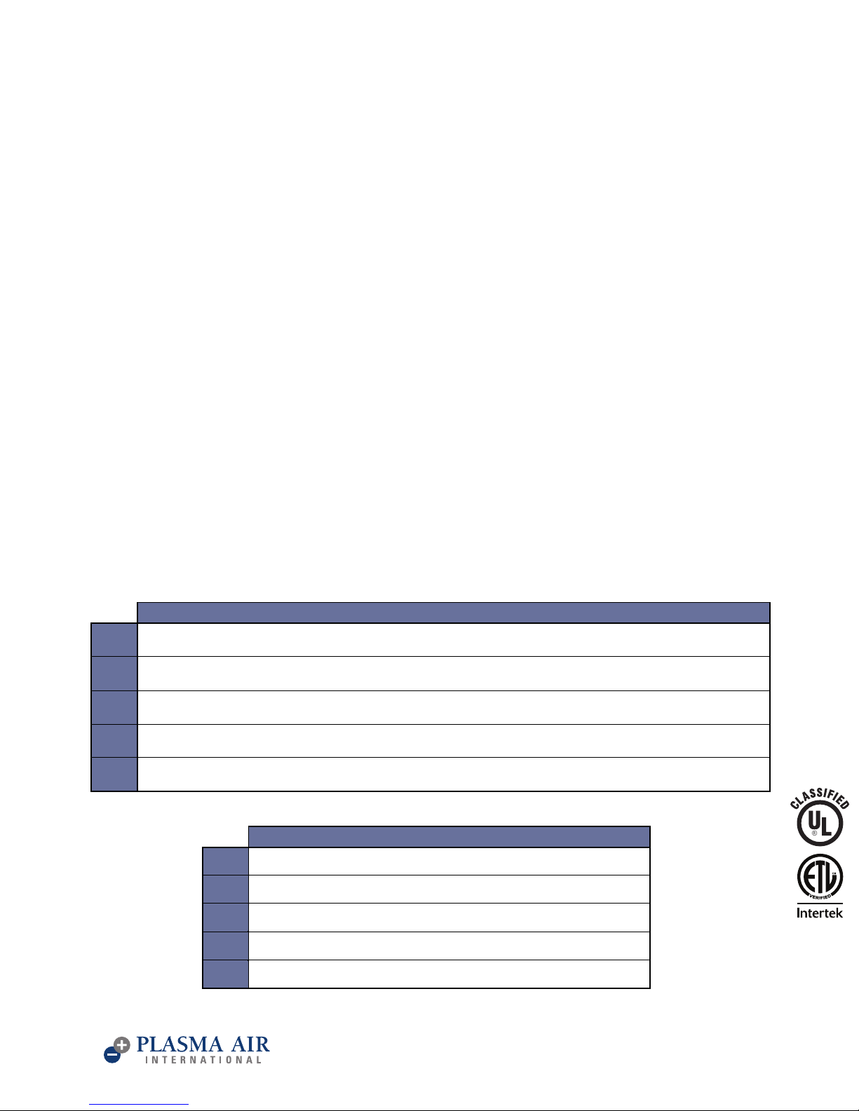
1) Screw the ionization tubes into the back of the transformer
while gently holding the grounding clip away from the tube.
2) For residential installations, the preferred location is in the
supply air duct leaving the AHU. Be sure to pick a location
before any branch duct take-offs.Verify that there is sufficient
duct depth to allow clearance for the tube – see figure 1.
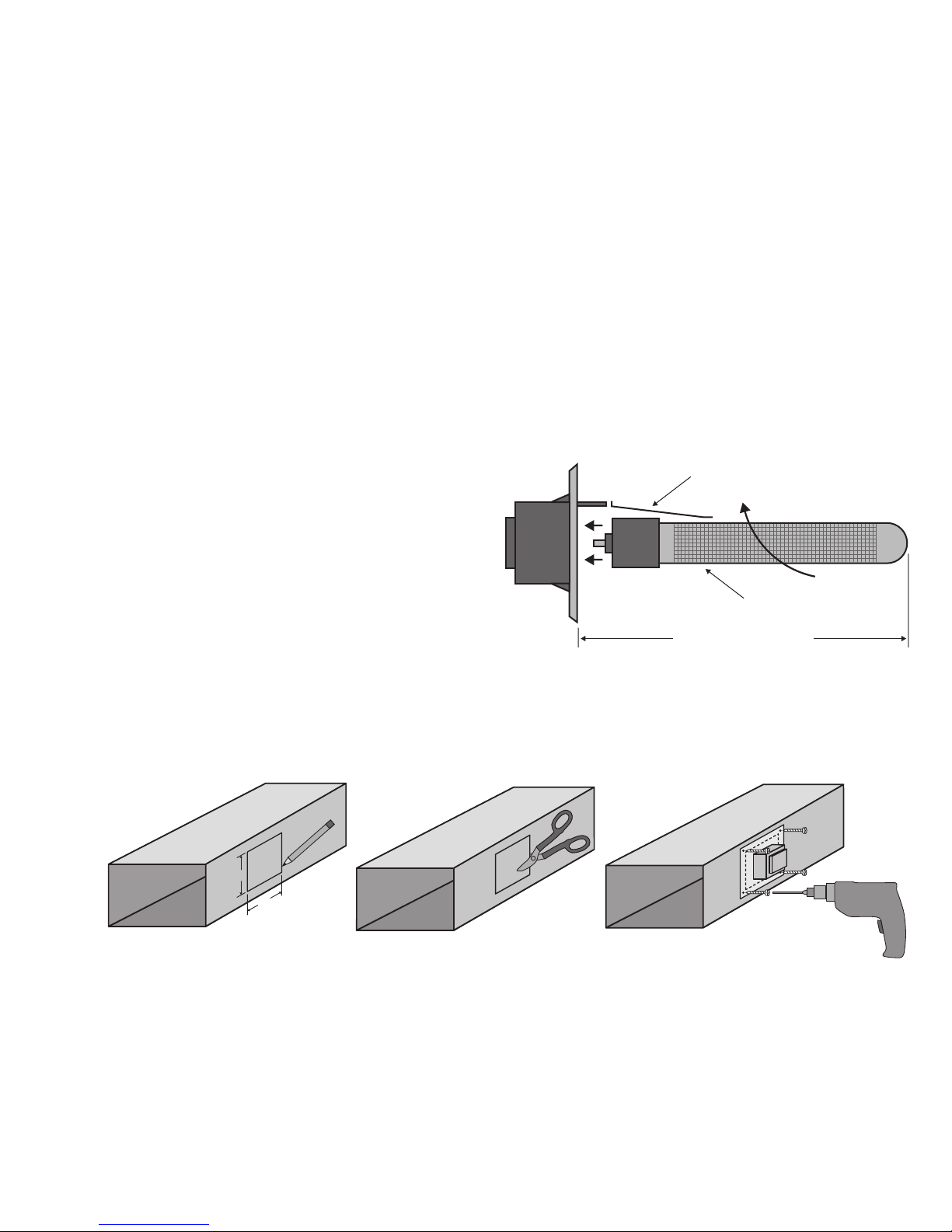
To mount the units in a duct:
a) Trace a 5½“ by 5½“ square on the surface of the duct onto
which you are mounting the model 200. The units have a
flange gasket that forms a seal between the duct and the mounting plate.
b) Cut out the traced portion of the duct using snips or sheet metal shears.
c) Screw the model 200 onto the duct using sheet metal screws.
3) If the unit cannot be installed in the preferred location due to space or temperature limitations, see Figure 2 for
alternate locations. Units can be installed using “L” shaped brackets available from many hardware suppliers or by
cutting a hole in the AHU or furnace casing.
4)
For commercial applications, the units are not typically mounted in the supply air duct as these ducts may not be easily
accessible for tube replacement or other service. Units are commonly mounted inside a roof top AHU using “L” shaped
brackets available at many hardware suppliers. Be sure to select a location within the air handling unit where there is
good air flow. One such location is immediately next to the fan inlet.
Mounting location notes:
•Ensure sufficient airflow over
the ionization tubes.
•Do not mount the units before
the system filter.
•Do not mount downstream of
a gas or oil fired furnace.
•Avoid locations where moisture
may be present like downstream
of a cooling coil.
ELECTRICAL INSTALLATION INSTRUCTIONS
Warning: The secondary voltage at the ionizing tubes can be 3,000 Volts AC. Do not connect to power before the installation
is complete. Always disconnect power to the unit before handling any of the unit components.
To reduce the risk of electric shock, this equipment has a grounding type plug that has a third (grounding) pin. This plug
will only fit into a grounding type power outlet. If the plug does not fit into the outlet, contact qualified personnel to install
the proper outlet. Do not alter the plug in any way.
1) The Model 200 is available in two primary voltage models, nominally 120 volts AC (model 201) or 230 volts AC (model 202).
The units may be used on 50 cycle or 60 cycle frequencies. Verify that the model 200’s voltage is the same as the available
voltage by checking the UL label on the unit.
2) The typical model 200 unit draws about 20 Watts. The power source should not be protected by a breaker exceeding
20 amps.
3) The unit should be powered when the system supply fan is energized. This can be accomplished by any of the
following methods:
•On systems with single speed supply fans, the fan power supply can be used.
•Use an airflow switch in series with the unit’s power supply.
•Install a relay off the 24 volt fan control circuitry and wire the unit’s power wiring through the NO contacts
•Install a supply fan power current sensing relay and wire the unit’s power wiring through the NO contacts
•Wire into the “EC” (Electronic Air Cleaner) contacts provided on the AHU.
•On systems where the above fan interlocking options are not available, contact your distributor/dealer or lasma Air
directly for an AFS-MF unit. This product is a mounting frame with an integral pressure differential switch that allows
the unit to be plugged into any 120 volt receptacle.
O ERATION
The ionization adjustment knob is a six-position switch that is used to turn the unit on and adjust the level of ionization.
1) When the knob is in the “0” position, no power is being applied to the ionization tube and the green light is off. Rotating
the knob from “0” through “5” increases the ionization output and will illuminate the green light.
2) The ionization level is set by the installing contractor and does not require adjustment on a regular basis. A guide is
provided on the back cover of this manual to set the ionization level based on the ollutant Load Factor.
3) The benefit of the ionization system is only realized when the supply fan is running. So to achieve improved air quality,
run the fan continuously or use an IAQ type thermostat such as a Lux model CAG 1500 which will cycle the fan once an
hour at specified times of the day.
IONIZATION TUBE
GROUNDING CLIP
TUBE CLEARANCE
D=10½”, E=14½”
FIGURE 1 – MODEL 200 AND IONIZATION TUBE
(c)(b)
(a)
LASMA AIR INTERNATIONAL 35 MELROSE LACE STAMFORD, CT 06902 203-662-0800 info@plasma-air.com www.plasma-air.com LASMA AIR INTERNATIONAL 35 MELROSE LACE STAMFORD, CT 06902 203-662-0800 info@plasma-air.com www.plasma-air.com