manuals.online logo
Brands
  1. Home
  2. •
  3. Brands
  4. •
  5. Plast-O-Matic
  6. •
  7. Valve Positioner
  8. •
  9. Plast-O-Matic V200 User manual

Plast-O-Matic V200 User manual

INSTRUCTIONS
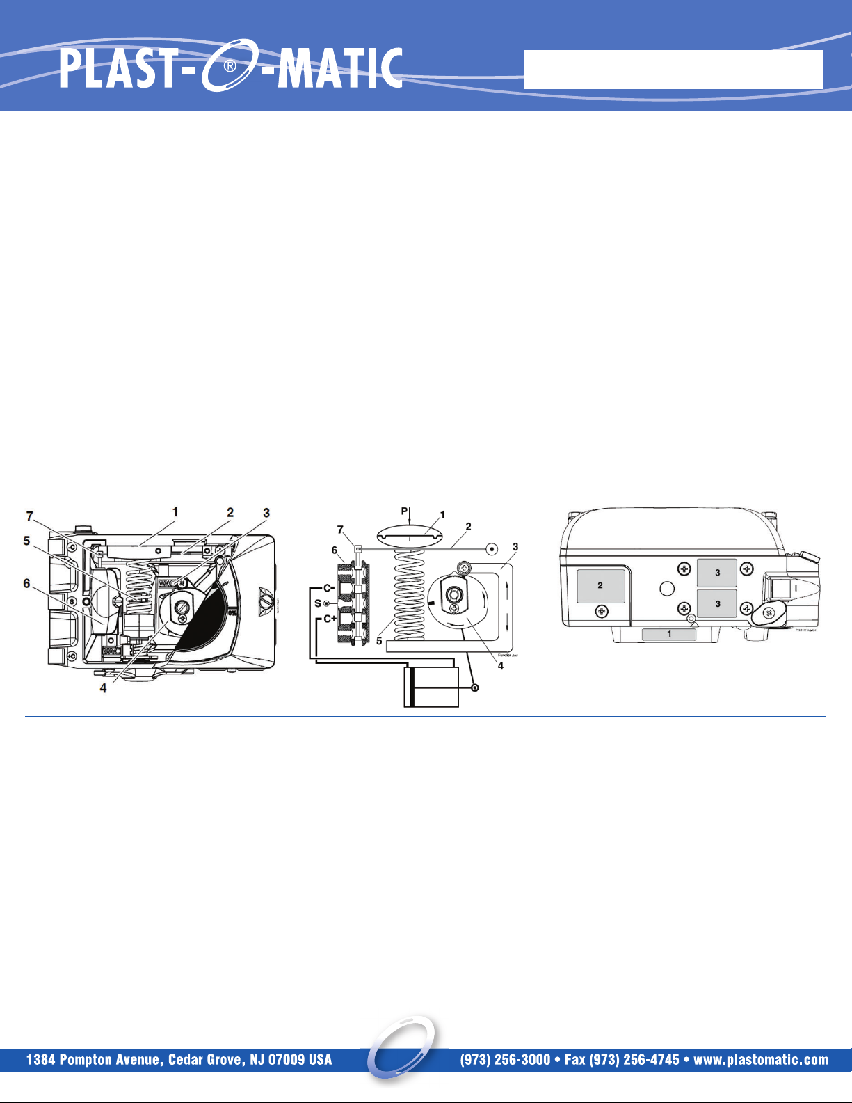
1.1 Principal of Operation
The V200 incorporates the force balance principal of operation. The
desired value, in the form of pressure, affects the membrane (1) with
the force that is created and transferred to the balance arm (2). The
opposing force, which represents the actual control value, is provided
by the feedback spring (5) and creating force in the opposite direction
on the balance arm (2). The feedback spring, resting on the feedback
arm (3), is positioned by the shape and response of the cam. The cam
(4) is connected to the cylinder’s (actuator) piston rod via the drive.
The pilot valve (6) is connected to the balance arm and follows the
balance arm’s movement. The system is stable when the gold plated
spool (7) is in the neutral position and the forces that affect the balance
arm is in equilibrium. As soon as signal change occurs or a change in
the position of the valve/actuator package occurs, the “force balance”
is also changed and the spool responds. Air immediately begins to
flow into the part of the actuator (C+ or C-) which allows the feedback
mechanism to return the spool to the neutral position.
The system is self-stabilizing and searches for a steady state position.
1.2 Product Identification
The V200 identification tags, Serial number tag (1), product model
tag (2) and feedback option tags (3) are placed as shown.
The product model tag contains information on control signal,
maximum working pressure and temperature ranges. Other
information can be shown depending on the model.
ELECTRO-PNEUMATIC POSITIONER
INSTALLATION AND MAINTENANCE
IMPORTANT: READ BEFORE USE
1. INTRODUCTION
Poor air quality is one of the main causes of premature functional
problems with pneumatic and electro-pneumatic equipment. The pilot
valve and IP-converter are precision instruments, and are therefore
the most sensitive parts of the positioner.
a) Water in the supply air is a natural occurrence. This happens when
air is compressed. The compression heats the air and the natural
degree of water in the air can remain as moisture. When the air cools
in pipes etc. the moisture condenses and becomes liquid water. Large
quantities can build and sometimes flood small water separators. This
excess water will eventually reach the control valve and positioner.
This can cause corrosion damage to the IP converter, causing the unit
to malfunction.
We strongly recommend the use of water separators with adequate
capacity. Coalescing filters from a reputable manufacturer is an
inexpensive way to help prevent unit malfunctions or failures, and add
life to the product. These filters remove particles and moisture from
air lines.
b) Oil in the supply air usually is from the main compressor. Oil can
clog the small nozzles and disturb the flapper in the IP-converter. It
can also cause the gold plated spool to “drag” within the pilot valve.
The result is poor control or in the worst case, failure.
c) Particles in the air usually occur because of corrosion. Dirt and
particles can block the small nozzles of the IP-converter. They can
also cause the pilot valve to malfunction. The unit may completely fail.
To ensure normal operational safety with VAC positioner products, we
recommend that a water separator and a <80 micrometer filter are
mounted as close to the product as possible. If large amounts of oil
are present an oil separator should be installed as well.
To further increase operational safety, we recommend that the
working air is clean, dry and free of moisture, water, oil, particles and
other contaminants, in accordance with the standard ANSI/SA –
7.0.01 – 1996.
1.3 Air quality recommendations
EPP-0514-I-1
2.2 4-20 mA connection
2.2.1 Connecting the control signal
Remove the front cover and indicator. (See page 15)
Terminal block (1) is now easily accessible. Connect the cables to
their respective pole.
Maximum cable size AWG 13 (2,5 mm2).
2.2.2 Checking the control signal
The control signal can be checked without having to break the signal
loop. This is done by connecting a low ohmic ampere meter over the
test points (2).
2.2.3 Bench test with the calibrator
When bench testing, it is possible to connect the control signal
(signal generator clips) to the two points (3), thus eliminating the
need for temporary leads.
2.2.4 Checking the IP internal circuit
With an ohm meter connected over the two test points (3) it is
possible to check the IP’s internal circuit.
At room temperature the meter should read ~150 – 200 ohms. No
reading indicates an internal circuit break and the IP converter needs
replacement.
2. INSTALLATION
2.1 Connections
S- Supply air V200P: max. 145 PSI/1MPa; V200E: 23 – 145
PSI/0.15 – 1 MPa
I– Input, pressure signal V200P: 3 – 15 PSI/20 – 100kPa;
V200E: Plugged
IE– Input, current signal V200E: 4 – 20 mA (Ri max 250 ohm);
V200P: Plugged
C+ - Actuator connection + stroke
C- - Actuator connection - stroke
OUT – All air from the actuator, IP and positioner is vented through
this port. Standard equipped with a bug screen/silencer
• Air connections for male 1/4” NPT or G 1/4”
• Gauge connections for male 1/8” NPT or G 1/8”
• Cable entry for male 1/2” NPT or M20 cable fittings.
• G threads are indicated by an engraved G on the air connection side
of the positioner.
• Gauge ports I, C+, C- and S are factory plugged. Remove plugs and
replace with gauges.
INSTRUCTIONS
!
The IP converter is factory-
adjusted. No extra range or
zero adjustments are
necessary.
2
3
3. SAFETY INSTRUCTIONS
CAUTION: Beware of moving parts when positioner is operated!
CAUTION: Beware of parts with live voltage! A voltage, which is
normally not dangerous, is supplied to the positioner. Avoid touching live
parts and bare wires as well as short circuiting live parts and the
housing.
CAUTION: Do not dismantle a pressurized positioner! Dismantling a
pressurized positioner will result in uncontrolled pressure release. Always
isolate the relevant part of the pipeline. Release the pressure from the
positioner and the piping. Failure to do this may result in damage or
personal injury.
CAUTION: Do not exceed the positioner performance limitations!
Exceeding the limitations marked on the positioner may cause
damage to the positioner, actuator and valve. Damage or personal
injury may result.
!
EPP-0514-I-2

Popular Valve Positioner manuals by other brands

ESCO Technologies ETS LINDGREN 2302-001 user manual

ESCO Technologies

ESCO Technologies ETS LINDGREN 2302-001 user manual

Samson FOUNDATION 3730-5 Mounting and operating instructions

Samson

Samson FOUNDATION 3730-5 Mounting and operating instructions

PI PIMAG V-417.6025E0 Series user manual

PI

PI PIMAG V-417.6025E0 Series user manual

Spirax Sarco PP 5 Series Installation and maintenance instructions

Spirax Sarco

Spirax Sarco PP 5 Series Installation and maintenance instructions

tissin TS800 Series instruction manual

tissin

tissin TS800 Series instruction manual

Dresser Masoneilan SVI II AP-2 quick start guide

Dresser

Dresser Masoneilan SVI II AP-2 quick start guide

Avid Technology SmartCal Series Installation and operating instructions

Avid Technology

Avid Technology SmartCal Series Installation and operating instructions

BESTEAM Bestis 1000 User and maintenance manual

BESTEAM

BESTEAM Bestis 1000 User and maintenance manual

Aventics R434001244 Service information

Aventics

Aventics R434001244 Service information

Samson TROVIS 3730-1 quick guide

Samson

Samson TROVIS 3730-1 quick guide

tissin TS600 Series instruction manual

tissin

tissin TS600 Series instruction manual

PI L-417.099211E1 user manual

PI

PI L-417.099211E1 user manual

Ytc YT-1000L installation manual

Ytc

Ytc YT-1000L installation manual

Pepperl+Fuchs PCV F200-B17-V1D Series manual

Pepperl+Fuchs

Pepperl+Fuchs PCV F200-B17-V1D Series manual

Aventics R431006322 Service information

Aventics

Aventics R431006322 Service information

Seg SP520 instruction manual

Seg

Seg SP520 instruction manual

Samson FOUNDATION 3730-5 Configuration manual

Samson

Samson FOUNDATION 3730-5 Configuration manual

KAUP 2T456Z operating manual

KAUP

KAUP 2T456Z operating manual

manuals.online logo
manuals.online logoBrands
  • About & Mission
  • Contact us
  • Privacy Policy
  • Terms and Conditions

Copyright 2025 Manuals.Online. All Rights Reserved.