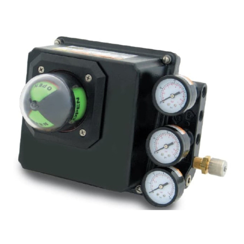
TLV CV10 User manual

To customers,
Regarding the operation of the Samson
electro-pneumatic positioner
Thank you for purchasing this electro-pneumatic positioner manufactured by Samson.
When shipped from the factory, the operating direction of the product is set to direct
action (when the input signal increases, the operating pressure increases).
If the operating direction of the control valve used with the positioner is direct action, set
the positioner to reverse action (when the input signal increases, the operating pressure
decreases).
Make sure to follow the instruction manual when changing the operating direction of the
positioner, mounting the positioner on the control valve, or adjusting the positioner.
TEL: 81-(0)79-427-1818
Rev. 10/2021 (T)

172-65098M-06 (Electro-pneumatic Positioner for CV10) 7 October 2021
Electro-pneumatic Positioner
for Control Valve CV10
Copyright © 2021 by TLV CO., LTD.
All rights reserved

172-65098M-06 (Electro-pneumatic Positioner for CV10) 7 Oct 2021
1
Contents
Introduction.........................................................................1
Safety Considerations ........................................................2
Specifications .....................................................................4
Configuration ......................................................................5
Principle of Operation.........................................................6
Maintenance.......................................................................6
Mounting on the Control Valve ...........................................7
Electrical Wiring..................................................................9
Air Connections ..................................................................9
Zero Point Adjustment......................................................10
Span Adjustment ..............................................................12
Troubleshooting................................................................15
TLV EXPRESS LIMITED WARRANTY ............................17
Service..............................................................................19
Introduction
Thank you for purchasing theelectro-pneumatic positioner for the TLV control
valve CV10.
This product has been thoroughly inspected before being shipped from the
factory. When the product is delivered, before doing anything else, check the
specifications and external appearance to make sure nothing is out of the
ordinary. Also be sure to read this manual carefully before use and follow the
instructions to be sure of using the product properly.
If detailed instructions for special order specifications or options not contained in
this manual are required, please contact TLV for full details.
This instruction manual is intended for use with the model(s) listed on the front
cover. It is necessary not only for installation, but for subsequent maintenance,
disassembly/reassembly and troubleshooting. Please keep it in a safe place for
future reference.

172-65098M-06 (Electro-pneumatic Positioner for CV10) 7 Oct 2021
2
Safety Considerations
Read this section carefully before use and be sure to follow the instructions.
Installation, inspection, maintenance, repairs, disassembly, adjustment and valve
opening/closing should be carried out only by trained maintenance personnel.
The precautions listed in this manual are designed to ensure safety and prevent
equipment damage and personal injury. For situations that may occur as a result of
erroneous handling, three different types of cautionary items are used to indicate the
degree of urgency and the scale of potential damage and danger: DANGER,
WARNING and CAUTION.
The three types of cautionary items above are very important for safety: be sure to
observe all of them as they relate to installation, use, maintenance, and repair.
Furthermore, TLV accepts no responsibility for any accidents or damage occurring as
a result of failure to observe these precautions.
Symbols
Indicates a DANGER, WARNING or CAUTION item.
Indicates an urgent situation which poses a threat of death or serious
injury
Indicates that there is a potential threat of death or serious injury
Indicates that there is a possibility of injury or equipment/product
damage
Install properly and DO NOT use this product outside the
recommended operating pressure, temperature and other
specification ranges.
Improper use may result in such hazards as damage to the product or
malfunctions that may lead to serious accidents. Local regulations may
restrict the use of this product to below the conditions quoted.
Use hoisting equipment for heavy objects (weighing
approximately 20 kg or more).
Failure to do so may result in back strain or other injury if the object
should fall.
Take measures to prevent people from coming into direct contact
with product outlets.
Failure to do so may result in burns or other injury from the discharge
of fluids.
When disassembling or removing the product, wait until the
internal pressure equals atmospheric pressure and the surface of
the product has cooled to room temperature.
Disassembling or removing the product when it is hot or under
pressure may lead to discharge of fluids, causing burns, other injuries
or damage.
Continued on the next page
DANGER
WARNING
CAUTION
CAUTION

172-65098M-06 (Electro-pneumatic Positioner for CV10) 7 Oct 2021
3
Be sure to use only the recommended components when
repairing the product, and NEVER attempt to modify the product
in any way.
Failure to observe these precautions may result in damage to the
product and burns or other injury due to malfunction or the discharge
of fluids.
Do not use excessive force when connecting threaded pipes to
the product.
Over-tightening may cause breakage leading to fluid discharge, which
may cause burns or other injury.
Use only under conditions in which no freeze-up will occur.
Freezing may damage the product, leading to fluid discharge, which
may cause burns or other injury.
Use only under conditions in which no water hammer will occur.
The impact of water hammer may damage the product, leading to fluid
discharge, which may cause burns or other injury.
Make sure the power supply is OFF before carrying out work on
the wiring or inspections involving disassembly.
If such work is carried out with the power on, there is a danger that
equipment may malfunction or electric shock may occur, leading to
injury or other accidents.
Make sure that wiring work requiring a special license is carried
out only by qualified personnel.
If carried out by unqualified personnel, overheating or short circuits
leading to injury, fires, damage or other accidents may occur.
When using this product, be sure NEVER to stand close to, or
leave tools anywhere near, moving parts such as a shaft.
Contact with moving parts or objects becoming caught in moving parts
could lead to injury, damage or other accidents.
CAUTION

172-65098M-06 (Electro-pneumatic Positioner for CV10) 7 Oct 2021
4
Specifications
Install properly and DO NOT use this product outside the recommended
operating pressure, temperature and other specification ranges.
Improper use may result in such hazards as damage to the product or
malfunctions which may lead to serious accidents. Local regulations
may restrict the use of this product to below the conditions quoted.
CAUTION
Use only under conditions in which no freeze-up will occur. Freezing
may damage the product, leading to fluid discharge, which may cause
burns or other injury.
CAUTION
Electro-pneumatic Positioner (partial list of standard specifications)
Input Current/Resistance
4 to 20 mA DC/approximately 200
Air Supply Pressure
0.14 to 0.6 MPaG
Air Connection Port
Rc(PT)1/4/Optional: NPT1/4
Pressure Gauge
Positioner supply side: 0 to 0.6 MPaG
Electrical Line Port
G(PF)1/2
Connection Method
Conduit method, Pressure-resistant packing method
Protection Class
IP54
Ambient Temperature
-20 to 50 °C (no freezing)
Materials of Construction
Body: Die-cast aluminum
Exposed parts: Stainless steel (SUS316 equivalent)
Air Consumption
At air supply pressure 0.14 MPaG: 0.15 Nm3/h
At air supply pressure 0.6 MPaG: 0.5 Nm3/h
Maximum Air Processing Capacity
At air supply pressure 0.14 MPaG: 2.5 Nm3/h
At air supply pressure 0.6 MPaG: 7 Nm3/h
Motive Medium
Oil-free air, filtered to 5 m
(1 MPa = 10.197 kg/cm2)

172-65098M-06 (Electro-pneumatic Positioner for CV10) 7 Oct 2021
5
Configuration
Diagram of Principle of Operation
Interior
No.
Name
No.
Name
1
Lever for Valve Travel
9.1
Feeler Pin
1.1
Stem
10
Nozzle Block
(with operating direction symbol)
2
Span Adjustment Pin
2.1
Nut
10.1
Nozzle
3
Distance Ring
10.2
Flapper
4
Zero Point Adjustment Screw
11
Cover Plate
5
Mounting Bolt
12
Amplifier (pilot valve)
6
Measurement Spring
13
Gain Adjustment –Xp
6.1
Limit Stop
14
Volume Adjustment –Q
7
Mounting Screw
15
Mounting Bolt
8
Measurement Diaphragm
20
Feedback Plate
9
Coupling
21
I/P Transducer
12
1.1 20
2.1
Relative positions of
nozzle and flapper
during reverse action < >
Amount of
valve opening
4
5
6
8
68
9
10
10.1
10.2
Output
Supply
iPPe
Pst 12
13
9
10
10.2
9.1
10.111
36
9
21
14
I
9.1
45 6.1 63
1
15
8
7
10.2
13
14
21

172-65098M-06 (Electro-pneumatic Positioner for CV10) 7 Oct 2021
6
Principle of Operation
(See the “Diagram of Principle of Operation”in the “Configuration”section on p. 5.)
The I/P transducer (21) converts the DC electrical input signal current W (4 –20 or
0 –20 mA) from a controller, etc. into a proportional output air pressure signal Pe (0.02
–0.1 MPa). The air pressure Pe produces a force in the measurement diaphragm (8)
opposing the reaction force from the measurement spring (6). The motion of the
measurement diaphragm (8) is transmitted via the feeler pin (9.1) to the flapper (10.2)
and thereby adjusts the opening of the nozzle (10.1). When either the pneumatic
operation signal Pe or the valve opening changes, the pressure changes inside the
amplifier (12: pilot valve), which is connected downstream of the nozzle (10.1). This
change causes the adjusted operating pressure to be altered and the valve stem of the
control valve to be moved to a position corresponding to its desired set point. The
volume adjustment (14) and gain adjustment-Xp (13) are used to adjust the opening
and closing speed of the positioner; to optimize the control loop. The type of
measurement spring (6) used is determined by the rated control valve opening and the
rated span for the desired set point; the spring may be exchanged if necessary.
Maintenance
Take measures to prevent people from coming into direct contact with
product outlets. Failure to do so may result in burns or other injury from
the discharge of fluids.
CAUTION
Be sure to use only the recommended components when repairing the
product, and NEVER attempt to modify the product in any way. Failure to
observe these precautions may result in damage to the product or burns
or other injury due to malfunction or the discharge of fluids.
CAUTION
Operational Inspection
A visual inspection of the following items should be done on a daily basis to determine
whether the valve is operating properly or has failed, and periodically (at least
biannually) the operation should be checked.
Inspection Item
Inspection Method
Remedy for Failure (Malfunction)
Operating
Conditions
Visual Inspection:
Is the valve opening (travel)
undergoing frequent change?
Change the controller’s set point
Adjust the air supply (Q) and the
proportional band (gain adjustment-Xp)
inside the positioner
Visual Inspection:
Does the valve opening match
the value displayedon the
controller?
Adjust the positioner’s zero point and
the span
Parts Inspection
When parts have been removed, or during periodic inspections, use the following table
to inspect the parts and replace any that are found to be defective.
Procedure
Positioner: Check to make sure there is no water or oil pooling when the positioner cover is opened
Filter in the Filter Regulator installed on the Positioner: Check for clogging
Span Adjustment Pin: Check for wear
Packing for the Positioner Cover: Check for deterioration
As this is a precision instrument, avoid disassembling the parts whenever possible.
When disassembly is necessary, please consult TLV.

172-65098M-06 (Electro-pneumatic Positioner for CV10) 7 Oct 2021
7
Mounting on the Control Valve
Before mounting the positioner, determine on which side (left or right) of the control
valve the positioner is to be attached, and confirm the proper operation of both the
actuator and the positioner itself. Then proceed with positioner mounting.
Refer to the Control Valve CV10 instruction manual for installation procedures.
Positioning the Positioner and the Actuator
Refer to the “Standard”diagram (below) for the relationships between the actuator
direction of operation, positioner direction of operation and the positioner mounting
location.
The positioner’s direction of operation may be changed after installation. It is necessary
to change the positioner mounting location whenever changes have been made to the
positioner control loop or when the fail-safe mode of the actuator has been changed
from “fail closed”to “fail open”or vice versa, etc.
Standard
Direct Action (Air to Close/Fail Open)
Direct Action (Air to Open/Fail Closed)
When there is a loss of operating air or input
signal, the control valve opens (the actuator
stem retracts).
When there is a loss of operating air or input
signal, the control valve closes (the actuator
stem extends).
Option
(Possible by repositioning the positioner installation and the internal parts)
Reverse Action (Air to Close/Fail Open)
Reverse Action (Air to Open/Fail Closed)
When there is a loss of operating air only, the
control valve opens (the actuator stem retracts).
When there is a loss of input signal only, the
control valve closes (the actuator stem extends).
When there is a loss of operating air only, the
control valve closes (the actuator stem extends).
When there is a loss of input signal only, the
control valve opens (the actuator stem retracts).
Supply
Pressure
Lever for
Valve Travel
Feedback
Plate
Pst
W
Pst
W
Supply
Pressure
1
2
Supply
Pressure
Pst
W
Supply
Pressure
Pst
W

172-65098M-06 (Electro-pneumatic Positioner for CV10) 7 Oct 2021
8
Determining and Changing the Direction of Operation
When the input signal W (desired set point) increases, the operating pressure pst
increases (direct action <<; standard).
When the input signal W (desired set point) increases, the operating pressure pst
decreases (reverse action <>; option).
In precisely the same manner, when the input signal decreases, the operating pressure
for direct action << decreases, and the operating pressure for reverse action <>
increases. The set direction of operation is indicated by the symbol that is visible on the
nozzle block. If the direction of operation indicated by the symbol does not match the
direction of operation that is required by the function of the control loop, or if for some
reason the direction of operation must be changed, use the following procedure (see
the figures below):
Remove both of the screws on the cover plate (11) and hold down the nozzle block (10)
while removing the cover plate (11). Turn the nozzle block (10) 180, then place the
cover plate (11) on top of the nozzle block (10) and retighten the screws. Make sure
that the relative position of the nozzle block (10) [on which the flapper (10.2) is
attached] to the feeler pin (9.1) is as shown in the figure below. After changing the
direction of operation as described above, fasten the positioner onto the top of the yoke
on the opposite side of the control valve.
Make sure that the lever for valve travel (1) and the feedback plate (20) are aligned
correctly with each other (see the “Mounting on the Control Valve”section).
Direct Action << (Standard)
Flapper beneath Feeler Pin
Reverse Action <> (Option)
Flapper above Feeler Pin
Measurement Spring
Feeler Pin
Flapper
Symbol

172-65098M-06 (Electro-pneumatic Positioner for CV10) 7 Oct 2021
9
Electrical Wiring
Make sure the power supply is OFF before carrying out work on the
wiring or inspections involving disassembly. If such work is carried out
with the power on, there is a danger that equipment may malfunction or
electric shock may occur, leading to injury or other accidents.
CAUTION
Make sure that wiring work requiring a special license is carried out only
by qualified personnel. If carried out by unqualified personnel,
overheating or short circuits leading to injury, fires, damage or other
accidents may occur.
CAUTION
When using this product, be sure NEVER to stand close to, or leave tools
anywhere near, moving parts such as a shaft. Contact with moving
parts or objects becoming caught in moving parts could lead to injury,
damage or other accidents.
CAUTION
For the electrical wiring, use equipment such as cable clamps and twist-on G(PF)1/2
wire connectors. Connect the “+”end of the input signal to the “+ green”terminal, and
the “-”end to the “- blue”terminal on the terminal connector inside the positioner.
Connect the ground to the ground terminal connection inside the positioner body as well
as the terminal connection outside the positioner body.
Air Connections
Do not use excessive force when connecting threaded pipes to the
product. Over-tightening may cause breakage leading to fluid
discharge, which may cause burns or other injury.
CAUTION
The air connections are Rc(PT)1/4. Install all piping correctly, using joints for metal
piping or plastic piping. Before connecting, thoroughly blow out all air lines to remove
any cuttings, foreign matter, water, oil, etc. Install a filter/regulator, etc. on the positioner
and ensure that the air that is to be supplied is free of any moisture and dust. Make sure
that the supply air is of a suitable and stable pressure.

172-65098M-06 (Electro-pneumatic Positioner for CV10) 7 Oct 2021
10
Zero Point Adjustment
Make sure to adjust the positioner for the following cases:
1) When the positioner has been removed / attached or replaced
2) When the ambient temperature differs by 15 C or more from 25 C, even if
that temperature is within the specification range
Zero point adjustment is recommended after installing the positioner at the site as
vibration during transportation etc. may have caused the zero point to shift.
Adjustment of Direct Action (Air to Close, Fail Open)
1
Regulate each size of positioner supply
air pressure by using a regulator, etc.
2
If using a current generator to adjust the
zero point, set the output to 19.8 mA. If
using a controller to adjust the zero
point, set the output to 98.7%. (This
adjustment is to ensure that the control
valve fully closes at 20 mA or 100%.)
Turn the zero point adjustment screw (4)
slowly until the pressure gauge on the
positioner reads 0 MPaG (0 kg/cm2).
(Control valve is fully open.) When the
pressure has dropped to 0 MPaG (0
kg/cm2), turn the zero point adjustment
screw (4) slowly until the pressure
gauge on the positioner shows the
positioner supply air pressure.
(The valve is lowered and fully closed.)
3
If using a current generator to adjust the
zero point, set the output to 20 mA. If
using a controller to adjust the zero
point, set the output to 100%. Check to
make sure the pressure gauge on the
positioner indicates the supply air
pressure. (The valve is lowered and fully
closed.) If the pressure does not rise far
enough, readjust, starting from step 2.
4
When the valve is in the fully closed
position, as in step 3, check to make sure
that the connecting support plate is at 0%
(fully closed) on the stroke gauge. If the
valve opening reading does not indicate
0%, loosen the 2 bolts holding the stroke
gauge in place and adjust the stroke
gauge.
5
When the zero point adjustment is
complete, carry out a span adjustment.
There is no need, however, to adjust the
span if the span adjustment pin was
neither removed nor moved while the
positioner was detached.
Connecting
Support Plate
Stroke
Gauge
100%
50%
0%
Bolt
4
Zero Point Adjustment Screw
Pressure Gauge

172-65098M-06 (Electro-pneumatic Positioner for CV10) 7 Oct 2021
11
Adjustment of Reverse Action (Air to Open, Fail Closed)
1
Regulate each size of positioner supply air
pressure by using a regulator, etc.
2
Check to make sure that the connecting
support plate is at 0% (fully closed) on the
stroke gauge. If the valve opening reading
does not indicate 100%, loosen the 2 bolts
holding the stroke gauge in place and
adjust the stroke gauge.
3
If using a current generator to adjust the
zero point, set the output to 4.2 mA. If using
a controller to adjust the zero point, set the
output to 1.3%. (This adjustment is to
ensure that the control valve fully closes at
4 mA or 0%.) Turn the zero point
adjustment screw (4) slowly until the
pressure gauge on the positioner reads 0
MPaG (0 kg/cm2). When the pressure has
dropped to 0 MPaG (0 kg/cm2), turn the
zero point adjustment screw (4) slowly and
stop just at the point where the pressure
gauge on the positioner starts to move.
4
If using a current generator to adjust the
zero point, set the output to 4 mA. If using a
controller to adjust the zero point, set the
output to 0%. Do a visual check to make
sure that the pressure gauge on the
positioner reads 0 MPaG (0 kg/cm2). If the
pressure does not fall far enough, readjust,
starting from step 2.
5
When the zero point adjustment is complete,
carry out a span adjustment. There is no
need, however, to adjust the span if the span
adjustment pin was neither removed nor
moved while the positioner was detached.
Connecting
Support Plate
Stroke
Gauge
100%
50%
0%
Bolt
4
Zero Point Adjustment Screw
Pressure Gauge

172-65098M-06 (Electro-pneumatic Positioner for CV10) 7 Oct 2021
12
Span Adjustment
After the zero point adjustment is complete, if a control valve opening that properly
corresponds to the input signal (0% –50% –100%) from a controller, etc., cannot be
achieved, carry out a span adjustment.
If the positioner has been detached but the span pin was neither removed nor moved
while the positioner was detached, there is no need to adjust the span.
Additionally, as the designated positions of the stroke gauge on the valve and the
connecting plate support opening are confirmed by means of a visual check, there may
be slight operator-induced variation in valve opening (travel).
Adjustment of Direct Action (Air to Close, Fail Open)
1
If using a current generator to adjust
the zero point, set the output to 20 mA.
If using a controller to adjust the zero
point, set the output to 100%. At this
point, do a visual check to make sure
that the indication on the stroke gauge
on the valve is 0%. (The valve is
lowered and fully closed.)
Move toward the end of the lever
to increase travel (span)
Move toward the fulcrum
to decrease travel (span)
2
If using a current generator to adjust
the zero point, set the output to 12 mA.
If using a controller to adjust the zero
point, set the output to 50%. At this
point, do a visual check to make sure
that the indication on the stroke gauge
on the valve is 50%.
3
If using a current generator to adjust
the zero point, set the output to 4 mA. If
using a controller to adjust the zero
point, set the output to 0%. At this
point, do a visual check to make sure
that the indication on the stroke gauge
on the valve is 100%.
4
If the visual check in steps 2 and 3
reveals that the valve opening is smaller
than the desired valve opening, slide the
span adjustment pin (2) on the lever for
valve travel (1) approximately 2 mm
closer to the end of the lever and
secure.
If the valve opening is larger than the
desired valve opening, slide the span
adjustment pin (2) on the lever for valve
travel (1) approximately 2 mm closer to
the fulcrum and secure.
5
Proceed by adjusting the zero point,
then, until the valve opening is correct
at the 0%, 50% and 100% points,
repeat the sequence, alternately
adjusting the zero point and the span.
Fulcrum End of Lever
Span Adjustment Pin

172-65098M-06 (Electro-pneumatic Positioner for CV10) 7 Oct 2021
13
Adjustment of Reverse Action (Air to Open, Fail Closed)
1
If using a current generator to adjust
the zero point, set the output to 0 mA.
If using a controller to adjust the zero
point, set the output to 0%. Do a
visual check to make sure that the
indication on the stroke gauge on the
valve is 0%.
Move toward the end of the lever
to increase travel (span)
Move toward the fulcrum
to decrease travel (span)
2
If using a current generator to adjust
the zero point, set the output to 12
mA. If using a controller to adjust the
zero point, set the output to 50%. Do
a visual check to make sure that the
indication on the stroke gauge on the
valve is 50%.
3
If using a current generator to adjust
the zero point, set the output to 20
mA. If using a controller to adjust the
zero point, set the output to 100%.
Do a visual check to make sure that
the indication on the stroke gauge on
the valve is 100%.
4
If the visual check in steps 2 and 3
reveals that the valve opening is
smaller than the desired valve
opening, slide the span adjustment
pin (2) on the lever for valve travel (1)
approximately 2 mm closer to the end
of the lever and secure.
If the valve opening is larger than the
desired valve opening, slide the span
adjustment pin (2) on the lever for
valve travel (1) approximately 2 mm
closer to the fulcrum and secure.
5
Proceed by adjusting the zero point,
then, until the valve opening is
correct at the 0%, 50% and 100%
points, repeat the sequence,
alternately adjusting the zero point
and the span.
Fulcrum End of Lever
Span Adjustment Pin

172-65098M-06 (Electro-pneumatic Positioner for CV10) 7 Oct 2021
14
Adjusting the Proportional Band (Gain Adjustment (Xp) and Volume
Adjustment (Q))
With the desired set point for the input signal set to the 50% point of the range (using a
current generator, set the output to 12 mA; using a controller, set the output to 50%).
For actuators 700 cm2in size, set the volume adjustment Q (14) for the air supply to fully
open (turn to the left). For those of 240 –350 cm2, set it to the middle position.
If the control valve opening oscillates rapidly (hunting), adjust the positioner air supply
using the volume adjustment Q to halt the oscillation.
If the control valve opening continues to oscillate rapidly after adjusting using the
volume adjustment Q, adjust the gain adjustment Xp (13). For the gain adjustment Xp
setting, pay close attention to the relationship with the supply air pressure in the middle
of the graph (attached to the back of all positioner covers). The normal Xp setting is 3%.
When the supply air pressure is between 0.14 MPaG and 0.4 MPaG (1.44 barg and 4 barg),
open the gain adjustment Xp approximately one turn (turn to the right from fully closed).
If the gain adjustment Xp is opened too far, the lower half of the zero point will be lost,
due to the inability to sufficiently exhaust air.
For reverse action, the control valve will not be able to close fully, thus valve leakage will
occur.
For direct action, the control valve will not be able to open fully, thus there will be
insufficient valve opening.
NOTE: As modifying the gain adjustment Xp displaces the zero point, if the gain adjustment
Xp has been modified, proceed with zero point adjustment, as outlined on p.10 - 11.
(1 bar = 0.1 MPa = 1.0197 kg/cm2)
Gain Adjustment Xp Setting
Refer to the chart attached to the
back of all positioner covers.
13
Gain Adjustment Xp
14
Volume Adjustment Q
Zul. Supply Alim.
27090
180
0
Xp
(%)
5
4
3
2
1
0
6 bar 3 bar 1.4 bar
270
90180
0360

172-65098M-06 (Electro-pneumatic Positioner for CV10) 7 Oct 2021
15
Troubleshooting
Be sure to use only the recommended components when repairing the
product, and NEVER attempt to modify the product in any way. Failure to
observe these precautions may result in damage to the product or burns
or other injury due to malfunction or the discharge of fluids.
CAUTION
If the product fails to operate properly, use the following table to locate the cause and
remedy.
Problem
Cause
Diagnosis/Inspection
Remedy
Valve
leakage
The supply air
pressure to the
positioner is too high
Check the supply air pressure
to the positioner (refer to the
product specifications)
Re-set the positioner’s supply
air pressure; adjust the
positioner’s zero point
The positioner’s zero
point is off
Check the pressure on the
positioner’s pressure gauge
when the input signal is at zero
If the pressure on the
pressure gauge attached to
the positioner is raised, adjust
the positioner’s zero point
The inlet pressure for
the control valve is
too high
Check the inlet pressure for
the control valve
Reduce the inlet pressure
(Cv value and spring range
must be changed)
The valve and valve
seat are off-center
Move the valve stem up and
down and check to see if it
catches
Reassemble the bonnet
section correctly
The valve and valve
seat are worn
Check the valve and valve
seat
Replace with a new valve and
valve seat (use valve and
valve seat of a different
material than the ones being
replaced)
Control
valve
opening
does not
move
beyond a
certain
point
The bellowphragm in
the actuator is broken
Check to see if air is leaking
from the exhaust tap or from
the bellowphragm area
Replace with a new
bellowphragm (check to make
sure that the ambient
temperature is not too high)
Positioner’s internal
parts are broken
(the diaphragm is
cracked, etc.)
Check to see if any unusual
noise is coming from the
positioner
Replace with a new positioner
[check to see if the valve
opening (travel) is changing
frequently, and if the ambient
temperature is too high]
There is insufficient
supply air pressure to
the positioner
Check the supply air pressure
for the positioner (refer to the
product specifications)
Adjust the supply air pressure
for the positioner (refer to the
product specifications)
Controller is set
incorrectly
Check to see if an input signal
of 4 –20 mA is coming from
the controller
Check the controller setting
and correct if necessary
Continued on the next page

172-65098M-06 (Electro-pneumatic Positioner for CV10) 7 Oct 2021
16
Problem
Cause
Diagnosis/Inspection
Remedy
No
movement
at all
Air is not being
supplied to the
positioner
Make sure that the compressor
is operating as it should; make
sure that the regulator
connected to the positioner inlet
is set
Deliver supply air pressure to
the positioner (refer to the
product specifications)
The input signal
wiring is incorrectly
connected
Check the “+ green”and “- blue”
connection terminals in the
positioner; check the controller’s
connections
Correct the connections
The input signal is
not being input
Check that 4 –20 mA is being
output by the connection
terminals inside the positioner
Adjust the controller or
replace with a new controller
There is a short in
the I/P transducer
Check the internal resistance
(approx. 200 )
Replace with a new positioner
(check to make sure that the
ambient humidity of the
installation is not too high)
There is water or
oil inside the
positioner
Check to see if there is water or
oil entrained in the supply air;
check to see if the humidity at
the control valve piping location
is too high
Replace with a new positioner
or have the positioner
repaired (improve the quality
of the supply air)
Control
valve
opens and
closes too
slowly
There is water or
oil inside the
positioner
Check to see if there is water or
oil entrained in the supply air;
check to see if the humidity at
the control valve piping location
is too high
Replace with a new positioner
or have the positioner
repaired (improve the quality
of the supply air)
The nozzle and/or
adjuster(s) inside
the positioner are
clogged
Check the control valve operation
by directly manipulating the
measurement spring inside the
positioner
Have the positioner repaired
(improve the quality of the
supply air)
The filter/regulator
is clogged
Check the filter
Clean the filter or replace with
a new filter
Control
valve
opening is
unstable
The setting of the
controller is faulty
Check the set value based on
the controller’s PID parameters
Change the set value
The positioner has
been insufficiently
adjusted
Adjust the positioner’s
proportional band
[air supply (Q) and gain
adjustment (Xp)]

172-65098M-06 (Electro-pneumatic Positioner for CV10) 7 Oct 2021
17
TLV EXPRESS LIMITED WARRANTY
Subject to the limitations set forth below, TLV CO., LTD., a Japanese corporation
(“TLV”), warrants that products which are sold by it, TLV International Inc. (“TII”) or one
of its group companies excluding TLV Corporation (a corporation of the United States of
America), (hereinafter the “Products”) are designed and manufactured by TLV,
conform to the specifications published by TLV for the corresponding part numbers (the
“Specifications”) and are free from defective workmanship and materials. The party
from whom the Products were purchased shall be known hereinafter as the “Seller”.
With regard to products or components manufactured by unrelated third parties (the
“Components”), TLV provides no warranty other than the warranty from the third party
manufacturer(s), if any.
Exceptions to Warranty
This warranty does not cover defects or failures caused by:
1. improper shipping, installation, use, handling, etc., by persons other than TLV, TII or
TLV group company personnel, or service representatives authorized by TLV; or
2. dirt, scale or rust, etc.; or
3. improper disassembly and reassembly, or inadequate inspection and maintenance
by persons other than TLV or TLV group company personnel, or service
representatives authorized by TLV; or
4. disasters or forces of nature or Acts of God; or
5. abuse, abnormal use, accidents or any other cause beyond the control of TLV, TII
or TLV group companies; or
6. improper storage, maintenance or repair; or
7. operation of the Products not in accordance with instructions issued with the
Products or with accepted industry practices; or
8. use for a purpose or in a manner for which the Products were not intended; or
9. use of the Products in a manner inconsistent with the Specifications; or
10. use of the Products with Hazardous Fluids (fluids other than steam, air, water,
nitrogen, carbon dioxide and inert gases (helium, neon, argon, krypton, xenon and
radon)); or
11. failure to follow the instructions contained in the TLV Instruction Manual for the
Product.
Duration of Warranty
This warranty is effective for a period of one (1) year after delivery of Products to the
first end user. Notwithstanding the foregoing, asserting a claim under this warranty must
be brought within three (3) years after the date of delivery to the initial buyer if not sold
initially to the first end user.
ANY IMPLIED WARRANTIES NOT NEGATED HEREBY WHICH MAY ARISE BY OPERATION
OF LAW, INCLUDING THE IMPLIED WARRANTIES OF MERCHANTABILITY AND FITNESS
FOR A PARTICULAR PURPOSE AND ANY EXPRESS WARRANTIES NOT NEGATED
HEREBY, ARE GIVEN SOLELY TO THE INITIAL BUYER AND ARE LIMITED IN DURATION
TO ONE (1) YEAR FROM THE DATE OF SHIPMENT BY THE SELLER.
Exclusive Remedy
THE EXCLUSIVE REMEDY UNDER THIS WARRANTY, UNDER ANY EXPRESS WARRANTY
OR UNDER ANY IMPLIED WARRANTIES NOT NEGATED HEREBY (INCLUDING THE
IMPLIED WARRANTIES OF MERCHANTABILITY AND FITNESS FOR A PARTICULAR
PURPOSE), IS REPLACEMENT; PROVIDED: (a) THE CLAIMED DEFECT IS REPORTED TO
THE SELLER IN WRITING WITHIN THE WARRANTY PERIOD, INCLUDING A DETAILED

172-65098M-06 (Electro-pneumatic Positioner for CV10) 7 Oct 2021
18
WRITTEN DESCRIPTION OF THE CLAIMED DEFECT AND HOW AND WHEN THE CLAIMED
DEFECTIVE PRODUCT WAS USED; AND (b) THE CLAIMED DEFECTIVE PRODUCT AND A
COPY OF THE PURCHASE INVOICE IS RETURNED TO THE SELLER, FREIGHT AND
TRANSPORTATION COSTS PREPAID, UNDER A RETURN MATERIAL AUTHORIZATION
AND TRACKING NUMBER ISSUED BY THE SELLER. ALL LABOR COSTS, SHIPPING
COSTS, AND TRANSPORTATION COSTS ASSOCIATED WITH THE RETURN OR
REPLACEMENT OF THE CLAIMED DEFECTIVE PRODUCT ARE SOLELY THE
RESPONSIBILITY OF BUYER OR THE FIRST END USER. THE SELLER RESERVES THE
RIGHT TO INSPECT ON THE FIRST END USER’S SITE ANY PRODUCTS CLAIMED TO BE
DEFECTIVE BEFORE ISSUING A RETURN MATERIAL AUTHORIZATION. SHOULD SUCH
INSPECTION REVEAL, IN THE SELLER’S REASONABLE DISCRETION, THAT THE
CLAIMED DEFECT IS NOT COVERED BY THIS WARRANTY, THE PARTY ASSERTING THIS
WARRANTY SHALL PAY THE SELLER FOR THE TIME AND EXPENSES RELATED TO
SUCH ON-SITE INSPECTION.
Exclusion of Consequential and Incidental Damages
IT IS SPECIFICALLY ACKNOWLEDGED THAT THIS WARRANTY, ANY OTHER EXPRESS
WARRANTY NOT NEGATED HEREBY, AND ANY IMPLIED WARRANTY NOT NEGATED
HEREBY, INCLUDING THE IMPLIED WARRANTIES OF MERCHANTABILITY AND FITNESS
FOR A PARTICULAR PURPOSE, DO NOT COVER, AND NEITHER TLV, TII NOR ITS TLV
GROUP COMPANIES WILL IN ANY EVENT BE LIABLE FOR, INCIDENTAL OR
CONSEQUENTIAL DAMAGES, INCLUDING, BUT NOT LIMITED TO LOST PROFITS, THE
COST OF DISASSEMBLY AND SHIPMENT OF THE DEFECTIVE PRODUCT, INJURY TO
OTHER PROPERTY, DAMAGE TO BUYER’S OR THE FIRST END USER’S PRODUCT,
DAMAGE TO BUYER’S OR THE FIRST END USER’S PROCESSES, LOSS OF USE, OR
OTHER COMMERCIAL LOSSES. WHERE, DUE TO OPERATION OF LAW,
CONSEQUENTIAL AND INCIDENTAL DAMAGES UNDER THIS WARRANTY, UNDER ANY
OTHER EXPRESS WARRANTY NOT NEGATED HEREBY OR UNDER ANY IMPLIED
WARRANTY NOT NEGATED HEREBY (INCLUDING THE IMPLIED WARRANTIES OF
MERCHANTABILITY AND FITNESS FOR A PARTICULAR PURPOSE) CANNOT BE
EXCLUDED, SUCH DAMAGES ARE EXPRESSLY LIMITED IN AMOUNT TO THE PURCHASE
PRICE OF THE DEFECTIVE PRODUCT. THIS EXCLUSION OF CONSEQUENTIAL AND
INCIDENTAL DAMAGES, AND THE PROVISION OF THIS WARRANTY LIMITING REMEDIES
HEREUNDER TO REPLACEMENT, ARE INDEPENDENT PROVISIONS, AND ANY
DETERMINATION THAT THE LIMITATION OF REMEDIES FAILS OF ITS ESSENTIAL
PURPOSE OR ANY OTHER DETERMINATION THAT EITHER OF THE ABOVE REMEDIES IS
UNENFORCEABLE, SHALL NOT BE CONSTRUED TO MAKE THE OTHER PROVISIONS
UNENFORCEABLE.
Exclusion of Other Warranties
THIS WARRANTY IS IN LIEU OF ALL OTHER WARRANTIES, EXPRESS OR IMPLIED, AND
ALL OTHER WARRANTIES, INCLUDING BUT NOT LIMITED TO THE IMPLIED WARRANTIES
OF MERCHANTABILITY AND FITNESS FOR A PARTICULAR PURPOSE, ARE EXPRESSLY
DISCLAIMED.
Severability
Any provision of this warranty which is invalid, prohibited or unenforceable in any
jurisdiction shall, as to such jurisdiction, be ineffective to the extent of such invalidity,
prohibition or unenforceability without invalidating the remaining provisions hereof, and
any such invalidity, prohibition or unenforceability in any such jurisdiction shall not
invalidate or render unenforceable such provision in any other jurisdiction.
Other manuals for CV10
1
Table of contents
Popular Valve Positioner manuals by other brands
halstrup-walcher
halstrup-walcher PS*3**DP series instruction manual
Acoustical Systems
Acoustical Systems SMARTractor owner's manual
Samson
Samson EB 8075 EN Mounting and operating instructions
PI
PI PIMAG V-417.6211E0 Series user manual
Absolute Process Instruments
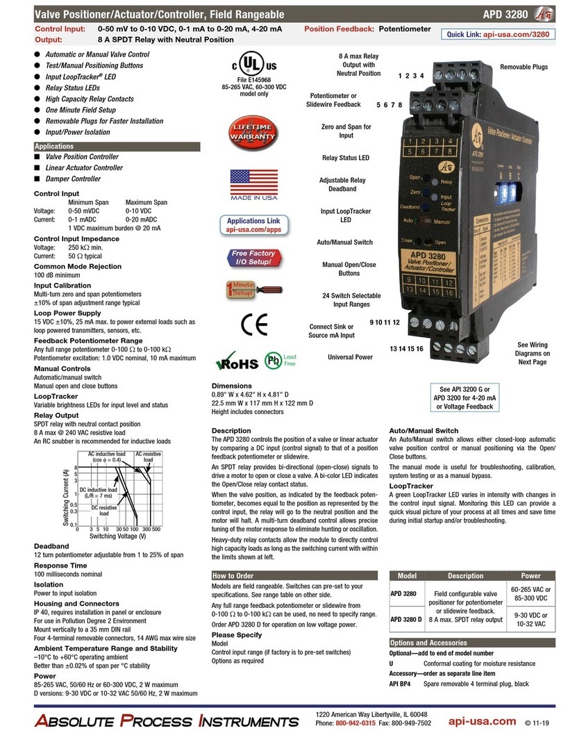
Absolute Process Instruments APD 3280 quick start guide

VAC
VAC V200 POSITIONER Installation, Calibration and Troubleshooting Manual
