Instruction Manual
D200149X012
3610J and 3620J Positioners
September 2017
2
Zero and Span Adjustments 26..................
Changing Positioner Action 27..................
Changing to Direct Action 28................
Changing to Reverse Action 28...............
Split Range Operation 29.......................
Characterized Cams for 3610J, 3610JP,
3620J, and 3620JP Positioners 30..............
Principle of Operation 31........................
Maintenance 34................................
Positioner Disassembly 36......................
Removing the Positioner from the Actuator 36.
Disassembling the Bypass Valve 37...........
Disassembling the Gauge Block 37...........
Disassembling the 3622
Electro‐Pneumatic Converter 38...........
Disassembling the Feedback
Lever Assembly 38.......................
Disassembling the Reversing
Plate and Gasket 39......................
Disassembling the Relay 39.................
Disassembling the Summing Beam
Assembly 39............................
Disassembling the Nozzle Assembly 40........
Disassembling the Input Module 41...........
Positioner Reassembly 41.......................
Assembling the Input Module 41.............
Assembling the Nozzle Assembly 42..........
Assembling the Summing Beam Assembly 42..
Assembling the Relay 43....................
Assembling the Reversing Plate
and Gasket 44..........................
Assembling the Gauge Block 44..............
Assembling the 3622
Electro‐Pneumatic Converter 44...........
Assembling the Feedback Lever Assembly 45...
Assembling the Bypass Valve Assembly 45.....
Changing Positioner Types 46...................
Parts Ordering 48...............................
Parts Kits 48..................................
Parts List 48..................................
Positioner Common Parts 48................
3622 Electro‐Pneumatic Converter 51.........
Diagnostic Connections 52..................
Loop Schematics 62.............................
Introduction
Scope of Manual
This instruction manual includes installation, operation, calibration, maintenance, and parts ordering information for
Fisher 3610J and 3620J positioners. (i.e. 3610J, 3610JP, 3611JP, 3620J, 3620JP, and 3621JP). This manual also provides
field installation information for the Fisher 3622 electro‐pneumatic converter. Refer to separate instruction manuals
for information on the actuator and control valve. Contact your Emerson sales office or Local Business Partner if
assistance is needed in obtaining actuator or control valve instruction manuals.
Do not install, operate or maintain a 3610J or 3620J positioner without being fully trained and qualified in valve,
actuator and accessory installation, operation and maintenance. To avoid personal injury or property damage it is
important to carefully read, understand, and follow all of the contents of this manual, including all safety cautions and
warnings. If you have any questions about these instructions, contact your Emerson sales office or Local Business
Partner before proceeding.
Description
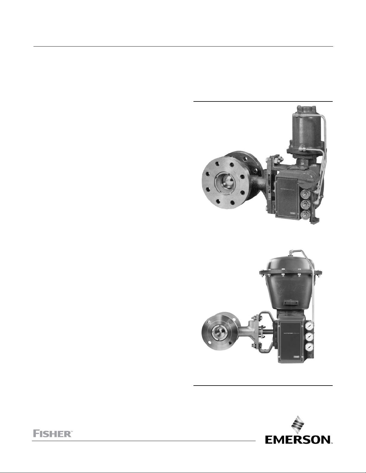
3610J or 3610JP pneumatic positioners and 3620J or 3620JP electro‐pneumatic positioners are used with diaphragm
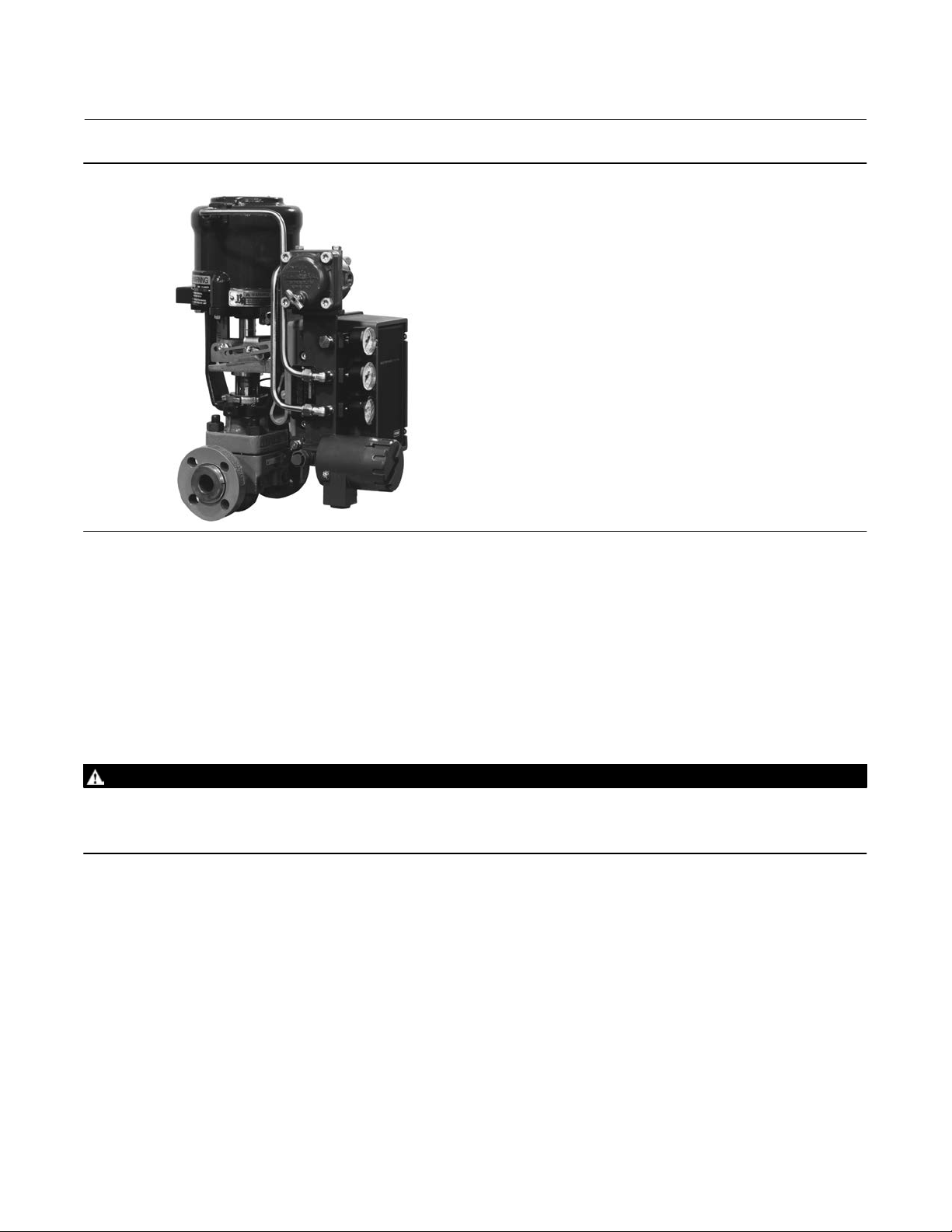
rotary actuators and piston rotary actuators as shown in figure 1. 3611JP and 3621JP positioners are used with Fisher
585, 585R, 585C, or 585CR sliding stem actuators as shown in figure 2.
The positioner mounts integrally to the actuator housing and provides a valve ball, disk, or plug position for a specific
input signal. The positioner accepts either a pneumatic or milliampere input signal. Refer to the Type Number
Description for a detailed explanation of type numbers.