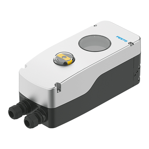
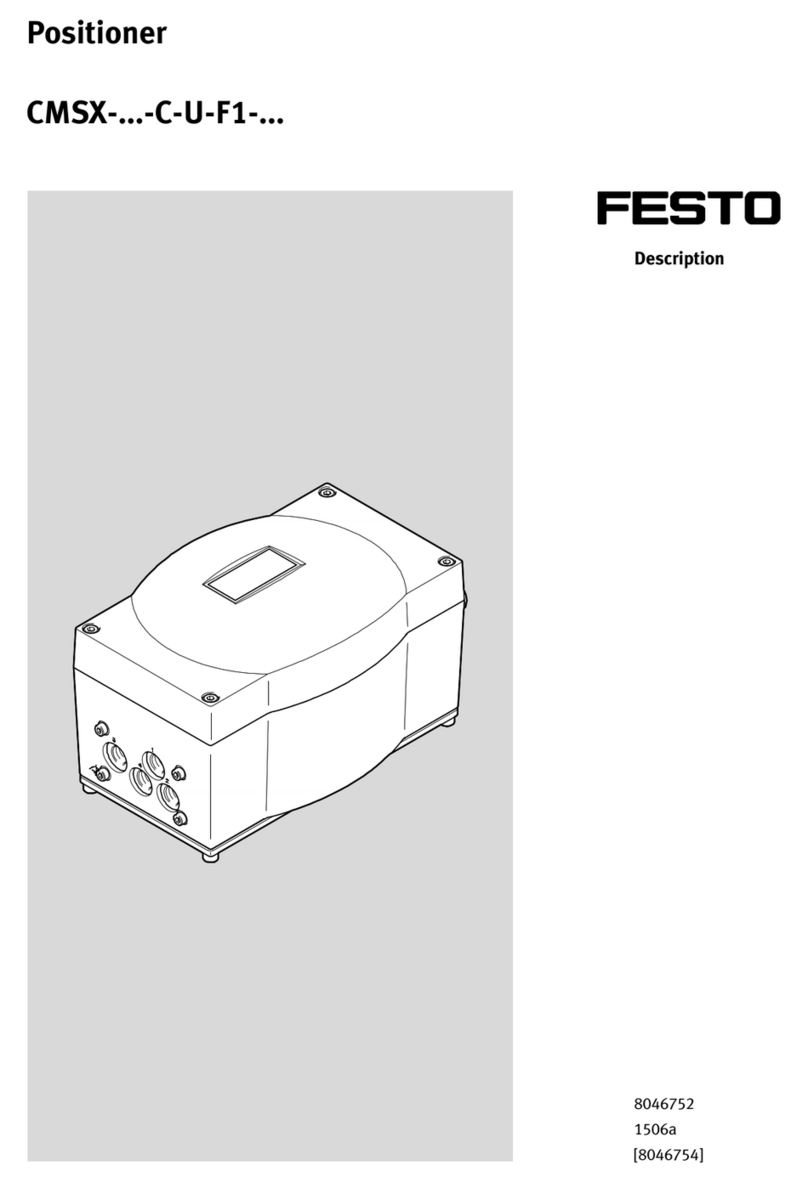
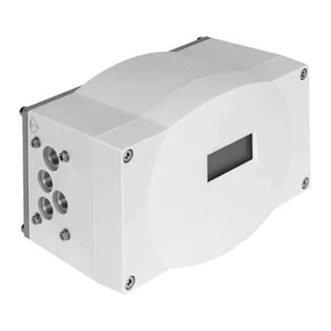
Festo CMSH User manual

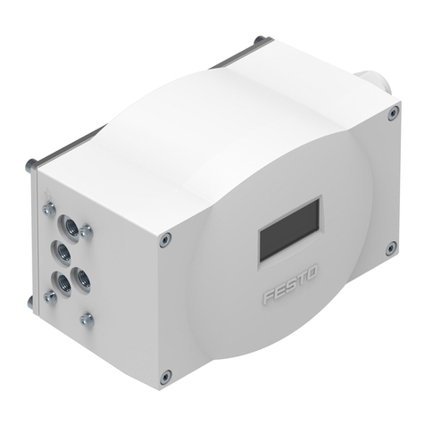
CMSH
Positioner
Operating instruc-
tions
8162856
2021-10
[8162858]

Translation of the original instructions

Festo — CMSH — 2021-10
3
Table of contents
1 About this document. . . . . . . . . . . . . . . . . . . . . . . . . . . . . . . . . . . . . . . . . . . . . . . . . . . . . . . . . . . . . 5
1.1 Applicable Documents. . . . . . . . . . . . . . . . . . . . . . . . . . . . . . . . . . . . . . . . . . . . . . . . . . . . . . 5
1.2 Product version. . . . . . . . . . . . . . . . . . . . . . . . . . . . . . . . . . . . . . . . . . . . . . . . . . . . . . . . . . . . 5
1.2.1 Licences. . . . . . . . . . . . . . . . . . . . . . . . . . . . . . . . . . . . . . . . . . . . . . . . . . . . . . . . . . 5
2 Safety. . . . . . . . . . . . . . . . . . . . . . . . . . . . . . . . . . . . . . . . . . . . . . . . . . . . . . . . . . . . . . . . . . . . . . . . . . 6
2.1 General safety instructions. . . . . . . . . . . . . . . . . . . . . . . . . . . . . . . . . . . . . . . . . . . . . . . . . . . 6
2.2 Intended use. . . . . . . . . . . . . . . . . . . . . . . . . . . . . . . . . . . . . . . . . . . . . . . . . . . . . . . . . . . . . . 6
2.3 Training of qualified personnel. . . . . . . . . . . . . . . . . . . . . . . . . . . . . . . . . . . . . . . . . . . . . . . . 6
3 Additional information. . . . . . . . . . . . . . . . . . . . . . . . . . . . . . . . . . . . . . . . . . . . . . . . . . . . . . . . . . . . 6
4 Product overview. . . . . . . . . . . . . . . . . . . . . . . . . . . . . . . . . . . . . . . . . . . . . . . . . . . . . . . . . . . . . . . . 7
4.1 Structure. . . . . . . . . . . . . . . . . . . . . . . . . . . . . . . . . . . . . . . . . . . . . . . . . . . . . . . . . . . . . . . . . . 7
4.1.1 Product design. . . . . . . . . . . . . . . . . . . . . . . . . . . . . . . . . . . . . . . . . . . . . . . . . . . . . 7
4.1.2 Product variant CMSH-...-V-SD-.... . . . . . . . . . . . . . . . . . . . . . . . . . . . . . . . . . . . . 8
4.1.3 Operation and display. . . . . . . . . . . . . . . . . . . . . . . . . . . . . . . . . . . . . . . . . . . . . . . 9
4.2 Function. . . . . . . . . . . . . . . . . . . . . . . . . . . . . . . . . . . . . . . . . . . . . . . . . . . . . . . . . . . . . . . . . 16
4.3 Safety position. . . . . . . . . . . . . . . . . . . . . . . . . . . . . . . . . . . . . . . . . . . . . . . . . . . . . . . . . . . . 16
5 Assembly. . . . . . . . . . . . . . . . . . . . . . . . . . . . . . . . . . . . . . . . . . . . . . . . . . . . . . . . . . . . . . . . . . . . . . 18
5.1 Mounting the pneumatic manifold block CAPS on the CMSH-...-V-SD-.... . . . . . . . . . . . . 18
5.2 Mounting on semi-rotary drives. . . . . . . . . . . . . . . . . . . . . . . . . . . . . . . . . . . . . . . . . . . . . . 18
5.2.1 Mounting the shaft adapter on the CMSH-S-.... . . . . . . . . . . . . . . . . . . . . . . . . 18
5.2.2 Mounting CMSH-S-VDE1-… on the semi-rotary drive. . . . . . . . . . . . . . . . . . . . . 19
5.2.3 Mounting CMSH-S-VDE2-... on the semi-rotary drive. . . . . . . . . . . . . . . . . . . . 20
5.3 Mounting on linear drives. . . . . . . . . . . . . . . . . . . . . . . . . . . . . . . . . . . . . . . . . . . . . . . . . . . 23
5.3.1 Mounting CMSH-SE-VDE1-D-… on linear drive DFPI-...-E-NB3 . . . . . . . . . . . . . 23
5.3.2 Mounting CMSH-SE-VDE2-D-… on linear drive DFPI-...-E-NB3VM12 . . . . . . . . 23
5.4 Adjusting position indicator on the CMSH-S-.... . . . . . . . . . . . . . . . . . . . . . . . . . . . . . . . . 24
6 Installation. . . . . . . . . . . . . . . . . . . . . . . . . . . . . . . . . . . . . . . . . . . . . . . . . . . . . . . . . . . . . . . . . . . . 25
6.1 Pneumatic installation. . . . . . . . . . . . . . . . . . . . . . . . . . . . . . . . . . . . . . . . . . . . . . . . . . . . . 25
6.1.1 Installing the pneumatics of the CMSH-…-VDE1-…. . . . . . . . . . . . . . . . . . . . . . 25
6.1.2 Installing the pneumatics of the CMSH-…-VDE2-…. . . . . . . . . . . . . . . . . . . . . . 25
6.2 Electrical installation. . . . . . . . . . . . . . . . . . . . . . . . . . . . . . . . . . . . . . . . . . . . . . . . . . . . . . . 27
6.2.1 Establish electrical connection. . . . . . . . . . . . . . . . . . . . . . . . . . . . . . . . . . . . . . 27
6.2.2 Wiring diagram. . . . . . . . . . . . . . . . . . . . . . . . . . . . . . . . . . . . . . . . . . . . . . . . . . . 28
7Commissioning. . . . . . . . . . . . . . . . . . . . . . . . . . . . . . . . . . . . . . . . . . . . . . . . . . . . . . . . . . . . . . . . . 28
7.1 Commissioning CMSH-.... . . . . . . . . . . . . . . . . . . . . . . . . . . . . . . . . . . . . . . . . . . . . . . . . . . . 28
7.2 Checking and setting parameters in the menu views. . . . . . . . . . . . . . . . . . . . . . . . . . . . . 29
7.2.1 Menu structure of the menu views. . . . . . . . . . . . . . . . . . . . . . . . . . . . . . . . . . . 29
7.2.2 ‘Guided setup’ menu. . . . . . . . . . . . . . . . . . . . . . . . . . . . . . . . . . . . . . . . . . . . . . 32
7.2.3 ‘Operation mode’ menu. . . . . . . . . . . . . . . . . . . . . . . . . . . . . . . . . . . . . . . . . . . . 36
7.2.4 ‘Settings’ menu. . . . . . . . . . . . . . . . . . . . . . . . . . . . . . . . . . . . . . . . . . . . . . . . . . . 37
7.2.5 ‘Initialization’ menu. . . . . . . . . . . . . . . . . . . . . . . . . . . . . . . . . . . . . . . . . . . . . . . 57
7.2.6 ‘Identification’ menu. . . . . . . . . . . . . . . . . . . . . . . . . . . . . . . . . . . . . . . . . . . . . . . 57

4
Festo — CMSH — 2021-10
7.2.7 ‘Service’ menu. . . . . . . . . . . . . . . . . . . . . . . . . . . . . . . . . . . . . . . . . . . . . . . . . . . . 58
7.2.8 ‘Diagnosis’ menu. . . . . . . . . . . . . . . . . . . . . . . . . . . . . . . . . . . . . . . . . . . . . . . . . 59
7.3 Completion of commissioning of the CMSH-.... . . . . . . . . . . . . . . . . . . . . . . . . . . . . . . . . . 66
8 Malfunctions. . . . . . . . . . . . . . . . . . . . . . . . . . . . . . . . . . . . . . . . . . . . . . . . . . . . . . . . . . . . . . . . . . . 66
8.1 Fault description. . . . . . . . . . . . . . . . . . . . . . . . . . . . . . . . . . . . . . . . . . . . . . . . . . . . . . . . . . 66
8.2 Messages. . . . . . . . . . . . . . . . . . . . . . . . . . . . . . . . . . . . . . . . . . . . . . . . . . . . . . . . . . . . . . . . 66
9 Disassembly. . . . . . . . . . . . . . . . . . . . . . . . . . . . . . . . . . . . . . . . . . . . . . . . . . . . . . . . . . . . . . . . . . . 77
10 Technical data. . . . . . . . . . . . . . . . . . . . . . . . . . . . . . . . . . . . . . . . . . . . . . . . . . . . . . . . . . . . . . . . . . 77
10.1 General data. . . . . . . . . . . . . . . . . . . . . . . . . . . . . . . . . . . . . . . . . . . . . . . . . . . . . . . . . . . . . . 77
10.2 Pneumatic data. . . . . . . . . . . . . . . . . . . . . . . . . . . . . . . . . . . . . . . . . . . . . . . . . . . . . . . . . . . 78
10.3 Electrical data. . . . . . . . . . . . . . . . . . . . . . . . . . . . . . . . . . . . . . . . . . . . . . . . . . . . . . . . . . . . 78
10.4 Operating and environmental conditions. . . . . . . . . . . . . . . . . . . . . . . . . . . . . . . . . . . . . . 81
10.5 Materials. . . . . . . . . . . . . . . . . . . . . . . . . . . . . . . . . . . . . . . . . . . . . . . . . . . . . . . . . . . . . . . . . 81

Festo — CMSH — 2021-10
About this document
5
1 About this document
1.1 Applicable Documents
All available documents for the product è www.festo.com/sp.
1.2 Product version
This document refers to the following product versions:
Product Version
CMSH from hardware revision 1.0.0
from software revision 1.0.0
Tab. 1: Product version
The product version can be determined from the product labelling or the local user interface.
There may be an updated version of this document for these or later product versions
è www.festo.com/sp.
1.2.1 Licences
This product uses open-source software. The following table lists the corresponding software pack-
ages as well as the licences that govern the software. The licensing conditions of the supplier apply.
Package Version Copyright notice SPDX License conditions
Little File System V2.0.1 Copyright 2017,
Arm Limited
BSD-3-
Clause
https://opensource.org/
licenses/BSD-3-Clause
STM32L4xx HAL
Drivers
V1.10.0 Copyright 2017,
STMicroelectronics
BSD-3-
Clause
https://opensource.org/
licenses/BSD-3-Clause
STM32L4xx CMSIS V5.4.0 Copyright
2009-2018,
Arm Limited
Apache
2.0
Apache License, Version 2.0
STM32L0xx CMSIS V1.9.0 Copyright 2016,
STMicroelectronics
BSD-3-
Clause
https://opensource.org/
licenses/BSD-3-Clause
STM32L0xx HAL
Drivers
V1.10.2 Copyright 2017,
STMicroelectronics
BSD-3-
Clause
https://opensource.org/
licenses/BSD-3-Clause
Tab. 2: Licences

6
Festo — CMSH — 2021-10
Additional information
2 Safety
2.1 General safety instructions
–Only use the product in original status without unauthorised modifications.
–Only use the product if it is in perfect technical condition.
–Observe labelling on the product.
–Only use the product in an industrial environment.
–Do not open the product in a damp environment.
–Before carrying out assembly, installation and maintenance work: switch off the compressed air
supply and secure it against being switched on again.
–After the compressed air supply is switched on, compressed air may be present directly at the
pneumatic working ports.
Return to Festo
Hazardous substances can endanger the health and safety of personnel and cause damage to the
environment. To prevent hazards, the product should only be returned upon explicit request by Festo.
–Consult your regional Festo contact.
–Complete the declaration of contamination and attach it to the outside of the packaging.
–Comply with all legal requirements for the handling of hazardous substances and the transport of
dangerous goods.
2.2 Intended use
The positioner is intended for positioning pneumatic drives.
The positioner is intended for use in an industrial environment.
The product is suitable for attachment to single-acting or double-acting semi-rotary drives or linear
drives.
The product is suitable for attachment to drives with a mechanical interface in accordance with
VDI/VDE 3845-1 (IEC 60534-6-2) or VDI/VDE 3847-2.
2.3 Training of qualified personnel
Work on the product may only be carried out by qualified personnel who can evaluate the work and
detect dangers. The qualified personnel have skills and experience in dealing with electropneumatic
(open-loop) control technology.
3 Additional information
–Contact the regional Festo contact if you have technical problems è www.festo.com.
–Accessories è www.festo.com/catalogue.

Festo — CMSH — 2021-10
Product overview
7
4 Product overview
4.1 Structure
4.1.1 Product design
2
7
6
9
4
1
12 1 11
3
5
7
10
8
Fig. 1: Product design
1
Threaded hole for mounting cable con-
nector
2
Housing cover
3
Position indicator (for product variant
CMSH-S-...)
4
Inspection window for the display
5
4 housing cover screws
6
Pneumatic manifold block
7
Mounting thread for mounting kit for semi-
rotary drives in accordance with VDI/VDE
3845-1
8
Check valve
9
Mounting thread for mounting kit for linear
actuators in accordance with IEC 60534-6-1
10
Shaft of the integrated position sensor
for displacement/angle measurement (for
product variant CMSH-S-...)
11
Housing bottom part
12
Functional earth (FE), equipotential
bonding

8
Festo — CMSH — 2021-10
Product overview
4 53
2
1
7 6
Fig. 2: Product design
1
Electrical connection, option module I/O (for
product variant CMSH-…-V2-...)
2
Electrical connection CMSH-...
3
Position indicator (for product variant
CMSH-S-...)
4
4 operating buttons
5
Display
6
Service interface
7
Functional earth (FE)
Electrical connection CMSH-...
–1 analogue input for power supply, setpoint specification and HART communication
–1 digital input for triggering functions
–1 input for an external position sensor
Electrical connection, optional module CMSH-…-V2-...
–1 analogue output for position feedback
–2 digital outputs for feedback of the device status and the position limit values
–1 digital input for triggering functions
4.1.2 Product variant CMSH-...-V-SD-...
The same device can be used for single-acting and double-acting drives with the product variant
CMSH-...-V-SD-....
The pneumatic manifold block CAPS determines the function type of the positioner.
The pneumatic manifold block CAPS required for operation is not pre-assembled and is not in scope of
delivery.

Festo — CMSH — 2021-10
Product overview
9
4.1.3 Operation and display
4.1.3.1 User interface
4
5
2
6
7
3
1
Fig. 3: Structure of the user interface
1
Display
2
Information area (optional)
3
Control ring
4
4 operating buttons
5
4 softkeys
6
Content area
7
Page indicator (optional)
Area Description
Information area Information about the status of the device is displayed in the process
views è Status and information in the information area.
Operating buttons The device is operated with 4 operating buttons.
Softkeys A context-dependent function is displayed. This function can be triggered
by the associated operating button. In the process views, the upper
softkey displays the device status.
Content area Process values, menus and parameters are displayed.
Page indicator The total number of process views and the relative position of the current
process view are displayed in the process views.
Tab. 3: Elements in the user interface
4.1.3.2 Process views
Process views
Message views
Menu views
Fig. 4: Basic layout of the views
The process views show current process values as well as information on the operating status. The
process views are automatically shown on the display when the device is switched on again or if there
is no interaction on the user interface for a long time.

10
Festo — CMSH — 2021-10
Product overview
The default process view of the positioner shows the current values of the setpoint position and actual
position. If the device is not initialised, the current actual position cannot be displayed.
Additional process views have been defined for automatic mode. Use the left and right keys for
navigation between the process views.
The following 5 process views are available in automatic mode. These process views are not available
in the manual operating modes è 7.2.3 ‘Operation mode’ menu:
Process view Description
1 Setpoint position [%]/actual position [%]
2 Setpoint value input [mA], analogue position feedback [mA]
3 Temperature [°C, °F]
4 Drive chamber pressures [bar, MPa, psi]
5 Supply pressure [bar, MPa, psi]
Tab. 4: Process views
Key functions
Symbol Function
Up key –Device status according to NAMUR recommendation NE 107
–Switch to the message views
Good
Maintenance required
Outside the specification
Functional check
Failure
Down key
Switch to the menu views
Left key
Switch to the previous process view
Right key
Switch to the next process view
Tab. 5: Key functions in the process views
Status and information in the information area
The following status and information can be displayed in the information area of the process views:
Symbol Information/status
Manual operation
Active control signal at the digital input

Festo — CMSH — 2021-10
Product overview
11
Symbol Information/status
–No valid initialisation
–Control not possible
–Effective tight seal
–Current setpoint position specification is in the tight seal range
Active blocking of local operation
Tab. 6: Status and information in the information area
4.1.3.3 Message views
Message views
Process views
Menu views
Fig. 5: Information structure
The following contents for a message are displayed in a message view:
3
24
1
5
Fig. 6: Structure of the message views
1
Message
2
Status signal of the message corresponding
to NAMUR recommendation NE 107
3
Unique message number
4
Message group
5
Page indicator
Active messages are displayed in the message views. If no active message is pending, a corresponding
message is displayed. If there are several messages pending, the highest priority message is dis-
played first.
The page indicator [5] is used for orientation and displays the rank of the displayed message and the
total number of all active messages. Active messages are called up when the upper key is pressed in
the process views è Key functions. The symbol belonging to the upper operating key indicates the
current device status in accordance with NAMUR recommendation NE 107 è Tab. 5 Key functions in

12
Festo — CMSH — 2021-10
Product overview
the process views. Since this general device status is derived from the status signal of the highest
priority active message, there is a direct connection between the device status and the associated
message at any time.
The right-hand key can be used to switch from one message to the next with lower priority. The left key
can be used to switch from one message to the next with the highest priority. When the message views
are exited, the last visible process view is displayed è Key functions.
Status signals in accordance with NAMUR recommendation NE 107
The messages are assigned to one of the following 4 status signals in accordance with NAMUR
recommendation NE 107 è Fig. 6 [2]. This assignment can be changed via DTM or EDD for some
diagnostic functions.
Status signal Function
Maintenance required
Outside the specification
Functional check
Failure
Tab. 7: Status signals
Message groups
The message groups facilitate classification in the evaluation and troubleshooting.
The message groups are based on the possible error sources of the NAMUR recommendation NE 107.
Message group Description
Drive Messages that refer to the pneumatic positioning system or the drive.
Configure Messages that refer to the missing or incorrect configuration of the posi-
tioner.
Electronics Messages that are due to errors in the electronics.
Operating conditions Messages that are the result of non-compliance with the specified oper-
ating conditions.
Process Messages that affect the process.
Sensor Messages that affect the position sensor, pressure sensor or temperature
sensor.
Other Other messages
Tab. 8: Message groups
A detailed description of the messages, possible causes and notes on error elimination can be found
in chapter è 8.2 Messages.

Festo — CMSH — 2021-10
Product overview
13
4.1.3.4 Menu views
Menu views
Process views
Message views
Fig. 7: Information structure
The menu views contain all the parameters, functions and information required for commissioning and
configuration of the device. A detailed description of the individual menus and parameters can be
found in chapter è 7.2 Checking and setting parameters in the menu views.
The menu views become visible by pressing the lower key in the process views.
Key functions
The following key functions are available for navigation and settings in the menu views. The key
functions are displayed context-dependent relevant to the current menu.
Symbol Function
Up key
–Exit menu: return from the top menu level to the last active process
view.
–Cancel: exit the settings view without saving the changes.
–Return to the next higher menu level.
Down key
–Select or deselect the focused parameter
–Navigate to the next lower menu level.
–Apply: exit the settings view and accept changes.
–Call a routine, action or wizard.
–Edit parameters: open settings view.
Left key
–Change selection: switch to the previous menu entry or selection option.
–Reduce parameter values.

14
Festo — CMSH — 2021-10
Product overview
Symbol Function
Right key
–Change selection: switch to the following menu entry or to the following
selection option.
–Increase parameter values.
Tab. 9: Key functions
Settings
Parameters can be changed in the menu views. The parameters are selected or adjusted via a value
input.
Discard or accept changes
Parameter changes are discarded when the upper key is pressed.
Parameter changes become effective when the lower key is pressed. The input symbol must be
selected in order to apply the change for numerical value entry, multiple selection and the user
characteristic curve. A curved arrow is visible on the input symbol. The input symbol is selected if it is
highlighted in black.
Actions with far-reaching consequences, such as calling the initialisation routine and resetting the
device, are protected by upstream queries. The critical action is not executed until the question is
confirmed.
Pattern Lower key for changing the
focused parameter
Lower key for accepting the
change
General principle —
Numerical value entry

Festo — CMSH — 2021-10
Product overview
15
Pattern Lower key for changing the
focused parameter
Lower key for accepting the
change
Multiple selection
User characteristic curve
Tab. 10: Accepting changes
Selection
During selection one or more options are selected from a list. There is a distinction between whether
just one or more options are permissible. After a single selection the value currently stored in the
system is displayed in the upper area.
Step-by-step value entry
With step-by-step value entry, a parameter value can be changed with the left and right keys. The
value currently stored in the system is displayed in the upper area and the permitted value range in
the lower area of the view.

16
Festo — CMSH — 2021-10
Product overview
1
2
Fig. 8: Value input
1
Currently valid system value
2
Permissible range of values
Numerical value entry
In the case of numerical value entry, a value is set by entering the individual decimal places. First,
the number to be edited is selected using the left and right keys. Then, the digit can be changed
analogously to the pattern for step-by-step value entry è Step-by-step value entry.
4.2 Function
The CMSH is a digital, electropneumatic positioner. It controls the position of a process valve that is
actuated by a pneumatic drive.
The CMSH is a 4 … 20 mA loop powered 2-wire device. An additional power supply is therefore not
required.
The CMSH has a local user interface (LUI) for configuration and operation. A HART interface permits
remote access and integration into higher-level systems.
The CMSH-S-... has an internal position sensor for position/angular detection. The angular position of
the shaft is detected by the internal position sensor.
Alternatively, an external potentiometric position sensor can be connected to the positioner on all
product variants.
4.3 Safety position
The safety position defines the pneumatic initial position of the positioner.
Depending on the product variant and the type of drive, the positioner reacts differently to the failure
of the electrical power supply, the failure of the compressed air supply or an impermissible setpoint
specification.
In the product variant CMSH-...-V-SD-... the pneumatic manifold block CAPS determines the function
type of the positioner and thus the safety position.

Festo — CMSH — 2021-10
Product overview
17
Single-acting drives Double-acting drives
Safety position in case
of electrical power failure,
pneumatic compressed
air supply present
CMSH-...-S-A-..., CAPS-...-S-A-... :
–Working port (2) on the posi-
tioner is exhausted.
–Drive moves to the initial posi-
tion.
CMSH-...-D-A-..., CAPS-...-D-A-... :
–Working port (2) on the posi-
tioner is exhausted, working
port (4) on the positioner is
pressurised.
–Drive moves to end position.
CMSH-...-D-C-..., CAPS-...-D-C-... :
–Working port (2) and (4) on the
positioner are closed.
–Drive holds last position.
Safety position in case of
failure of the compressed
air supply, electric power
present
CMSH-...-S-A-..., CAPS-...-S-A-... :
–Working port (2) on the posi-
tioner is exhausted.
–Drive moves to the initial posi-
tion.
CMSH-...-D-A-..., CAPS-...-D-A-... :
–Working port (2) on the posi-
tioner is exhausted, working
port (4) on the positioner is
open.
–Drive position not defined.
CMSH-...-D-C-..., CAPS-...-D-C-... :
–Working port (2) and (4) on the
positioner are closed.
–Drive holds last position.
Safety position in case
of failure of electrical
power and compressed
air supply
CMSH-...-S-A-..., CAPS-...-S-A-... :
–Working port (2) on the posi-
tioner is exhausted.
–Drive moves to the initial posi-
tion.
CMSH-...-D-A-..., CAPS-...-D-A-... :
–Working port (2) on the posi-
tioner is exhausted, working
port (4) on the positioner is
open.
–Drive position not defined.
CMSH-...-D-C-..., CAPS-...-D-C-... :
–Working port (2) and (4) on the
positioner are closed.
–Drive holds last position.
Tab. 11: Safety position
If the power supply is switched on again, the last operating status is effective immediately.

18
Festo — CMSH — 2021-10
Assembly
•
5 Assembly
5.1 Mounting the pneumatic manifold block CAPS on the CMSH-...-V-SD-...
1
23
Fig. 9: Mounting of pneumatic manifold block
CAPS
1
Positioner CMSH-...-V-SD-...
2
Pneumatic manifold block CAPS
3
4 retaining screws
Fasten the pneumatic manifold block CAPS to the positioner with 4 retaining screws.
–M4x20 retaining screws for CAPS-M1-VDE1-..., M4x10 retaining screws for CAPS-M1-VDE2-...
–Tightening torque: 2.7 Nm ± 10%
5.2 Mounting on semi-rotary drives
5.2.1 Mounting the shaft adapter on the CMSH-S-...
The shaft of the internal position sensor can be rotated as desired and does not have a mechanical
stop for the sensing range. The permissible sensing range of the position sensor is 115°.
The sensing range of the position sensor can be checked in Operation mode ‘Manual venting’
è 7.2.3.2 ‘Manual venting’ manual manipulated variable mode.
For the position sensor to work within its sensing range, the mounting position as well as the initial
position and direction of rotation of the drive must be taken into account when determining the shaft
adapter position on the shaft.

Festo — CMSH — 2021-10
Assembly
19
2.
34
2
1
5
Fig. 10: Shaft of the positioner
1
2 threaded pins
2
Shaft adapter
3
Detection range of the position/angular
detection position sensor
4
Shaft of the position sensor
5
Flat section of the shaft
1. Adjust the shaft by hand so the flat section of the shaft [5] is opposite the sensing range.
Secure the shaft adapter with a threaded pin, depending on the direction of rotation of the drive.
–Tightening torque: 0.5 Nm ± 15%
Depending on the direction of rotation of the drive, the shaft adapter must be fixed to the flat section
of the shaft with the threaded pin through one of the threaded holes on the shaft adapter.
5.2.2 Mounting CMSH-S-VDE1-… on the semi-rotary drive
This chapter describes the attachment of the positioner to a semi-rotary drive in accordance with
VDI/VDE 3845-1, IEC 60534-6-2.
Use a mounting kit for semi-rotary drives in accordance with VDI/VDE 3845-1, IEC 60534-6-2 , acces-
sories è 3 Additional information.

20
Festo — CMSH — 2021-10
Assembly
1
2
5
6
4
3
Fig. 11: Mount CMSH-S-VDE1-… on semi-rotary
drive
1
Semi-rotary drive
2
Mounting adapter
3
Positioner CMSH-S-VDE1-...
4
Shaft adapter
5
4 M5x8 retaining screws
6
4 M6x10 retaining screws
1. Determine the direction of rotation of the semi-rotary drive.
2. Fasten the mounting adapter to the semi-rotary drive with 4 M5x8 retaining screws.
–Tightening torque: 3 Nm ± 10%
3. Place the positioner with the shaft adapter on the mounting adapter and align it. The position
sensor must be within the sensing range of the semi-rotary drive è 5.2.1 Mounting the shaft
adapter on the CMSH-S-....
Make sure that transverse loads do not act on the shaft of the positioner during alignment.
4. Fasten the mounting adapter to the positioner with 4 M6x10 retaining screws.
–Tightening torque: 5 Nm ± 10%
5.2.3 Mounting CMSH-S-VDE2-... on the semi-rotary drive
This chapter describes the mounting of the positioner on a semi-rotary drive in accordance with
VDI/VDE 3847-2.
Other manuals for CMSH
1
Table of contents
Other Festo Valve Positioner manuals

Festo
Festo CMSX-...-C-U-F1 series User manual

Festo
Festo CPX Series Parts list manual

Festo
Festo CMSX-P-S-A1-C-U-F1-D series User manual

Festo
Festo CMSH User manual

Festo
Festo CMSX-P-S-C-U-F1-D-130-A User manual

Festo
Festo CMSX C-U-F1 Series User manual

Festo
Festo CMSX-P-S-C-U-F1-D-130-A User manual

Festo
Festo DG..-...-GA Series User manual

Festo
Festo EXCM-30 -PF Series User manual

Festo
Festo CMSX Series Operating and installation instructions