Redline TR1500 Supplement

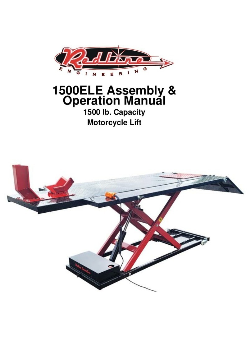
Redline TR1500 Trike Motorcycle Lift Table
Assembly & Operation Manual

Step 1
Use the provided bolts shown to secure the front wheel stop to the front of either the lift itself, or to the front
of the front extension panel if you intend to use the front extension panel. We do not recommend using the
front extension unless you actually have an unusually long motorcycle and require this panel.
This photo below shows the wheel stop installed.

Step 2
Assuming you wish to install the front extension, it slides over the front of the table as shown.

Be sure to line up the large holes on the sides of the front extension panel with the same holes found in the li table.
Next, you’ll install the front extension support pole. The TR1500 comes with 4 poles total as shown below. The 2 longest
poles support the side extensions (installed later). The middle length pole is an an-p stabilizer bar (installed later).
Finally, the shortest pole is the front extension support pole.

You’ll insert the shortest pole through the front extension panel and also through the li table at the same me,
resulng in the shortest pole slightly exing the front extension panel on both sides. Once done, you’ll insert the
provided clevis pin and coer pin on each side of the front extension support pole

Step 3
Next, you’ll insert the middle length pole into the base of the machine. This is an an-p stabilizer bar.

You’ll then use the pictured hardware to install the p-over feet into the ends of the p-over bar.

Step 4
In step 4, you’ll insert the 2 longest support poles into the 2 most rearward holes in the li’s tabletop, and then
slide the side extensions over those protruding bars.
Again, using the supplied hardware you’ll insert all 4 clevis and coer pins, eecvely pinning the side
extensions into place so that they cannot possibly slide o without intenonally doing so.

Step 5
Next, you’ll aach the 3 piece ramp assembly to the table top as shown using the hooks of the ramps to drop
into the holes in the table top, as well as the holes in the side extensions
Hardware is supplied to bolt all three ramps together, but we do not recommend doing so as it makes it
especially dicult to remove and replace the ramps when all three are connected. Nevertheless, the hardware
and bolt holes are included in case the customer wishes to do so.

Step 6
If you purchased the oponal wheel vise with your trike li, both your table and your front extension panel
come pre-drilled with the necessary mounng holes to install the Redline wheel vise to this table as shown. Be
sure to use ratchet straps to secure your bike to the li as the wheel vise alone is not sucient to hold the
motorcycle rmly to the li.

Step 7
Install the eye bolts into the front of the side extensions using the washer and nut as shown below. These eye
bolts allow you to aach ratchet straps to the table top and thus, rmly secure the load to the li.

Step 8
Now it’s me to connect your pump to the table. Simply remove the red cap as shown in the photo below and
thread the li’s hydraulic hose into the pump, being sure not to over ghten with pliers. Firm hand-ghtening
is ne.
Next, be sure to pull the small brass-colored vent into the upward posion as shown. This allows the pump
reservoir to breathe and allows air to come in and out of the reservoir during operaon.

The standard pump for the TR1500 will come with an air hose and hand operated air valve. If you wish to
operate your table via compressed air, you’ll now connect your air hose to the valve shown below. The air
motor poron of this pump requires at least 100 psi to operate. We do not recommend supplying more than
155 psi of compressed air to the pump as you may damage the air motor. The pump can either be operated by
manual input via the long foot pedal, or raised via air power by operang the hand control valve shown below.
In the event that your pump does not make enough pressure to meet the li’s maximum capacity of 1,500 lbs,
you may need to adjust the relief pressure of the pump. The relief pressure is the maximum amount of
pressure the pump can produce. In such a case, you’ll remove the red cap pictured below and locate this video
on YouTube and follow the steps. Be sure to never load more than 1,500 lbs onto your li. Adjusng your
pump’s pressure to allow it to li more than 1,500 lbs is not safe. We have tested this table with more than
1,500 lbs and determined that it will experience permanent structural deformaon of the frame if loaded
beyond 1,500 pounds. Thus, be extremely careful not to do this.

Step 9
If you purchased the oponal electric upgrade for the TR1500, you’ll connect your hydraulic hose as shown,
being sure not to over ghten with pliers. Firm hand-ghtening is ne.
Similar to the standard air-over-hydraulic pump, the release pressure of the electric pump can be raised by
locang and watching this dierent video on YouTube.
Remove the dipsck with red knob and add roughly 1 gallon of customer-supplied #32 hydraulic oil. Top o the reservoir
so it is full to the top, disregarding the hashmarks on the dipsck.

The electric pump already comes with a substanal amount of electrical cord. We do not recommend using a long, thin
extension cord to operate the electric pump as you may experience signicant “amp loss” and harm the motor. If you’re
going to use an extension cord, the shorter and thicker the size of the cord, the beer.
On the oponal electric pump upgrade, the green buon will raise the li, and the red buon kills power to the motor,
and the lever with black ball knob at the end will lower the li.

Step 10
It is recommended the customer always lower the li and rest the weight of the load onto the safety locks
when in use and not rely on the hydraulic pump to hold pressure in order to support the weight of the load. To
operate the safety lock, simply move this lever shown below to the le or right, respecvely, to engage and
disengage the safety locking bar, also pictured below toward the boom. Note that the li will not lower unl
it is slightly raised in order to free the safety lock bar of pressure, and the safety bar then moved to the
upward posion.

Step 11
The drop out panel is easily installed and removed with no tools or hardware. Noce in this picture below that
the side extension support pole runs through the drop out panel, eecvely rendering the drop out panel
ineecve for rear wheel removal. For this reason, rear re changes are typically not possible if the side
extensions are installed, so be sure to leave them o the table if this is your intent.

Step 12
To operate the casters and roll the li around your shop, use a large allen key to turn clockwise on the caster
post shown below. Spin the caster downward at each corner unl all four casters are supporng the weight of
the table and the frame of the table is no longer touching the ground. “DO NOT” aempt to lower the casters
if the li table is loaded as this will surely destroy the casters. The casters are only strong enough to support
the table itself, and nothing more.
Your Redline TR1500 is now ready for use. If you have technical quesons about your li, you can email us at
Tech@RedLineStands.com WE THANK YOU FOR YOUR BUSINESS!!
Other Redline Lifting System manuals