manuals.online logo
Brands
  1. Home
  2. •
  3. Brands
  4. •
  5. Platinum Tools
  6. •
  7. Cables And Connectors
  8. •
  9. Platinum Tools HPH16 User manual

Platinum Tools HPH16 User manual

This manual suits for next models

63

Popular Cables And Connectors manuals by other brands

Philips SWA6310 Specifications

Philips

Philips SWA6310 Specifications

StarTech.com CRJ4550PK quick start guide

StarTech.com

StarTech.com CRJ4550PK quick start guide

Nohau EMUL-IP2K-PC user guide

Nohau

Nohau EMUL-IP2K-PC user guide

Foxun SX-SP144E-HD4K2K operating instructions

Foxun

Foxun SX-SP144E-HD4K2K operating instructions

Philips SWA3305W Specifications

Philips

Philips SWA3305W Specifications

opticis Stretch DVIM1-1P0x user manual

opticis

opticis Stretch DVIM1-1P0x user manual

Volkswagen VAS 6558A operating manual

Volkswagen

Volkswagen VAS 6558A operating manual

NEXIBO N-13 user manual

NEXIBO

NEXIBO N-13 user manual

CYP PU-1H3HBTL Operation manual

CYP

CYP PU-1H3HBTL Operation manual

Allen-Bradley 1784-u2dhp installation instructions

Allen-Bradley

Allen-Bradley 1784-u2dhp installation instructions

Global Caché Flex Link Blaster quick start

Global Caché

Global Caché Flex Link Blaster quick start

Hauppauge USB-Live2 Quick installation guide

Hauppauge

Hauppauge USB-Live2 Quick installation guide

Fenix MPSV 15 installation manual

Fenix

Fenix MPSV 15 installation manual

BEGA 71 085 manual

BEGA

BEGA 71 085 manual

Tesla HPWC installation manual

Tesla

Tesla HPWC installation manual

GAMERON LUXURY TV CABLE instruction manual

GAMERON

GAMERON LUXURY TV CABLE instruction manual

molex Milli-Grid Dual row 87568 Series operating instructions

molex

molex Milli-Grid Dual row 87568 Series operating instructions

Burndy Continental Industries thermOweld CRE-7 instructions

Burndy

Burndy Continental Industries thermOweld CRE-7 instructions

manuals.online logo
manuals.online logoBrands
  • About & Mission
  • Contact us
  • Privacy Policy
  • Terms and Conditions

Copyright 2025 Manuals.Online. All Rights Reserved.

1
HPH Series J-Hook Installation Instructions
2
Mounting to a vertical surface: HPH16, HPH32, HPH48 and HPH64
Use a nail*, bolt* or screw* with a minimum head diameter of 0.329” (Fig.1-A) and an
appropriate length for the substrate (Fig.1-B) to fasten the HPH J-Hook (Fig.2) to the vertical
surface (Fig.3). Insert the cables and close the latch as shown in Fig.3. The latch must be in the
closed position as shown in Fig.4 to secure the cables and complete the installation.
Fig.1 Fig.2
Fig.3 Fig.4
Part
No.
Hook
Size
Fig.
No.
UL Load Rating
LBS. | N
Description
HPH16
1"
2 & 4
20
88.96
1” Standard HPH J-Hook, size 16
HPH32
2”
17
75.62
2” Standard HPH J-Hook, size 32
HPH48
3”
20
88.96
3” Standard HPH J-Hook, size 48
HPH64
4”
17
75.62
4” Standard HPH J-Hook, size 64
3
Mounting to a rod or ceiling wire with a Multi-Function Clip-Batwing: HPH16W,
HPH32W, HPH48W and HPH64W
HPHXXW J-Hooks (Fig.1) are pre-assembled to Multi-Function Clip-Batwings at the factory using
a fastener such as a rivet or a zinc plated ¼-20 x 3/8” pan head Phillips machine bolt and a
grade A ¼-20 hex Nylon locknut (Fig.2). A plain HPH J-Hook may be assembled to a UL listed
batwing clip in the field with the use of a similar fastener. Depress the batwing between your
fingers (Fig. 3). Attach the HPHXXW to 12 gauge ceiling wire or 1/4" threaded rod (Fig.4 and
Fig.6).Insert the cables and close the latch (Fig.5 and Fig.7). The latch must be in the closed
position as shown in Fig.8 to secure the cables and complete the installation.
Fig. 1 Fig. 2 Fig. 3
Fig. 4 Fig. 5
4
Fig. 6 Fig. 7
Fig. 8
Part No.
Hook
Size
Fig.
No.
UL Load Rating
LBS. | N
Description
HPH16W
1"
1
&
8
20
88.96
1” Batwing HPH J-Hook, size 16
HPH32W
2”
20
88.96
2” Batwing HPH J-Hook, size 32
HPH48W
3”
20
88.96
3” Batwing HPH J-Hook, size 48
HPH64W
4”
20
88.96
4” Batwing HPH J-Hook, size 64
5
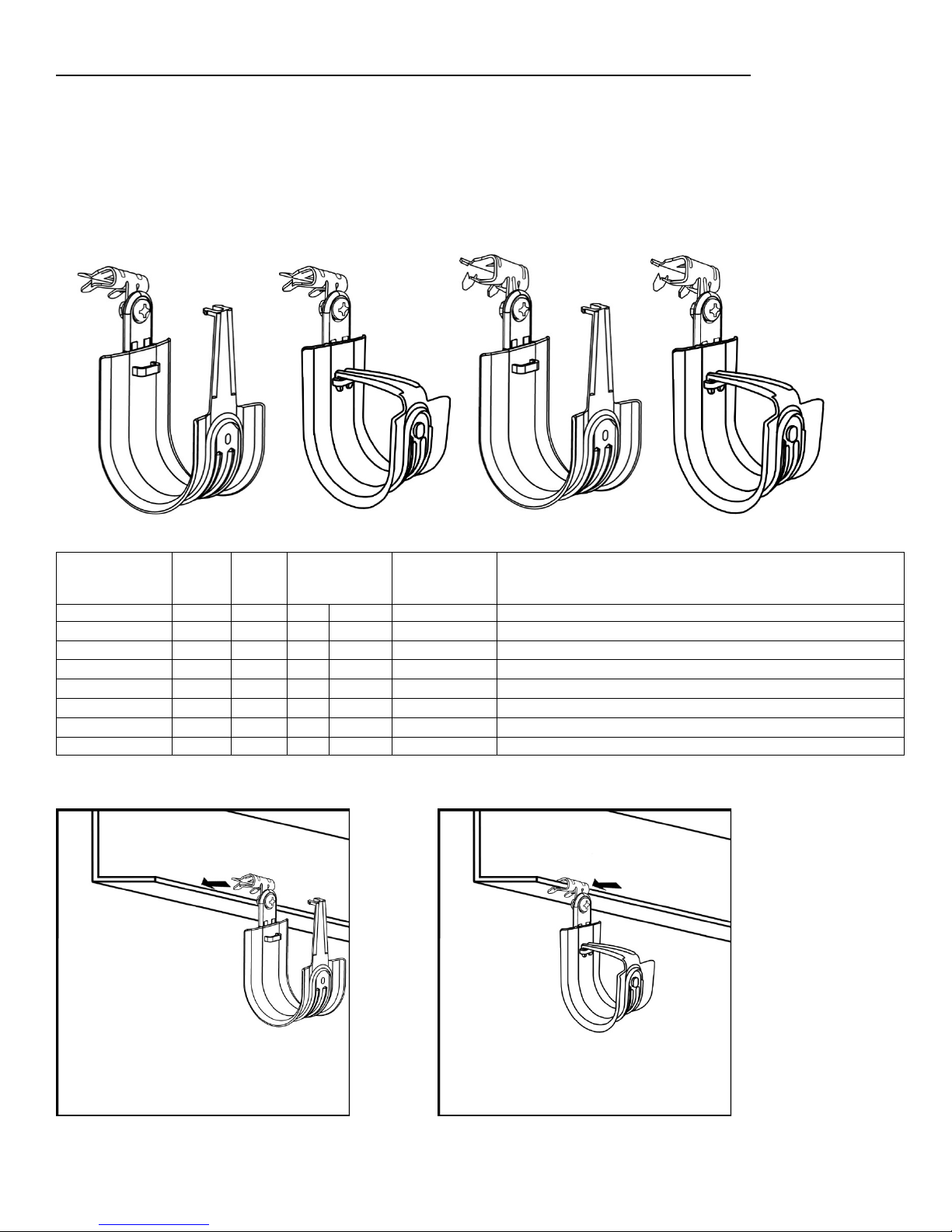
Mounting to a rod or a horizontal surface with an Angle Clip 90°:HPH16AC, HPH16AC6
HPH32AC, HPH32AC6, HPH48AC, HPH48AC6, HPH64AC & HPH64AC6
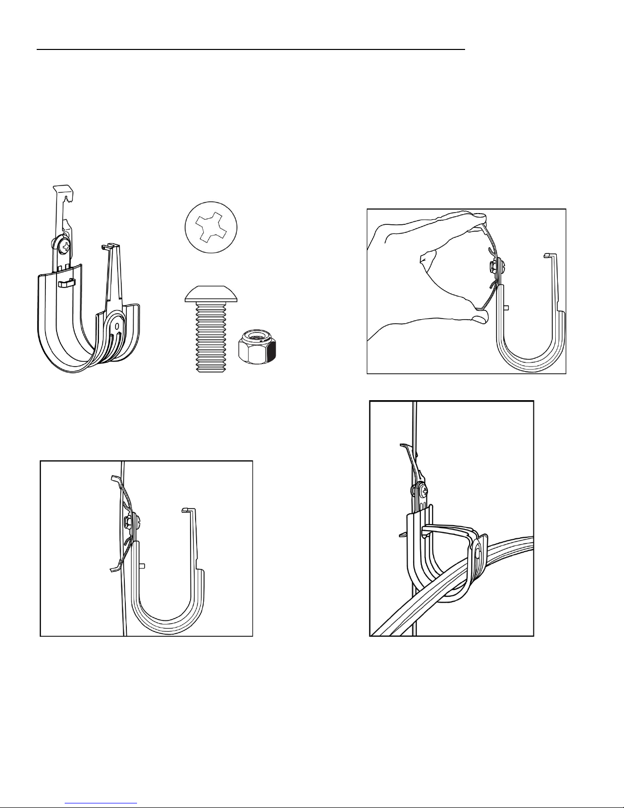
HPHXXAC and HPHXXAC6 J-Hooks (Fig.1 and Fig.2) are pre-assembled to Angle Clips 90° at the
factory using a fastener such as a rivet or a zinc plated ¼-20 x 3/8” pan head Phillips machine
bolt and a grade A ¼-20 hex Nylon locknut (Fig.3). A plain HPH J-Hook may be assembled to a
Platinum Tools Angle Clip 90° in the field using a similar fastener. Fasten the HPHXXAC or
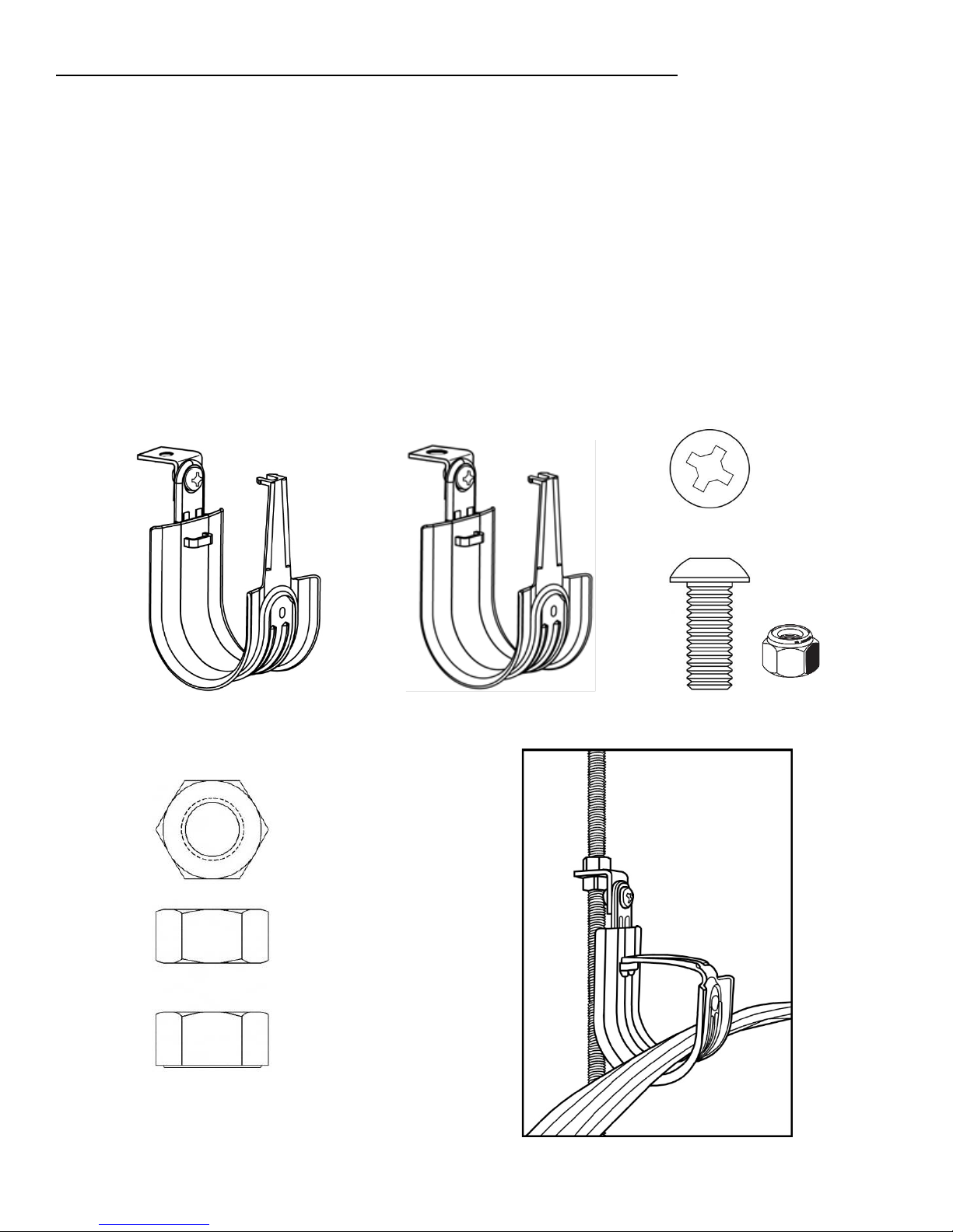
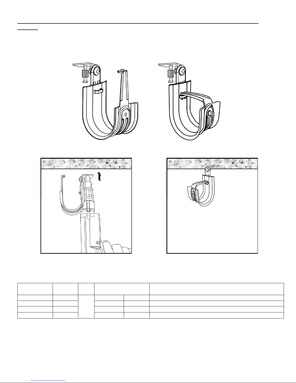
HPHXXAC6 to 1/4" or 3/8” threaded rod using two standard hex nuts (Fig.4). Thread a single nut
up to the desired location of the threaded rod. Guide the HPHXXAC or HPHXXAC6 onto the
threaded rod. Thread a second nut onto the threaded rod and tighten to the first nut, thereby
sandwiching the Angle Clip 90° between the two nuts (Fig.5). An HPHXXAC or an HPHXXAC6
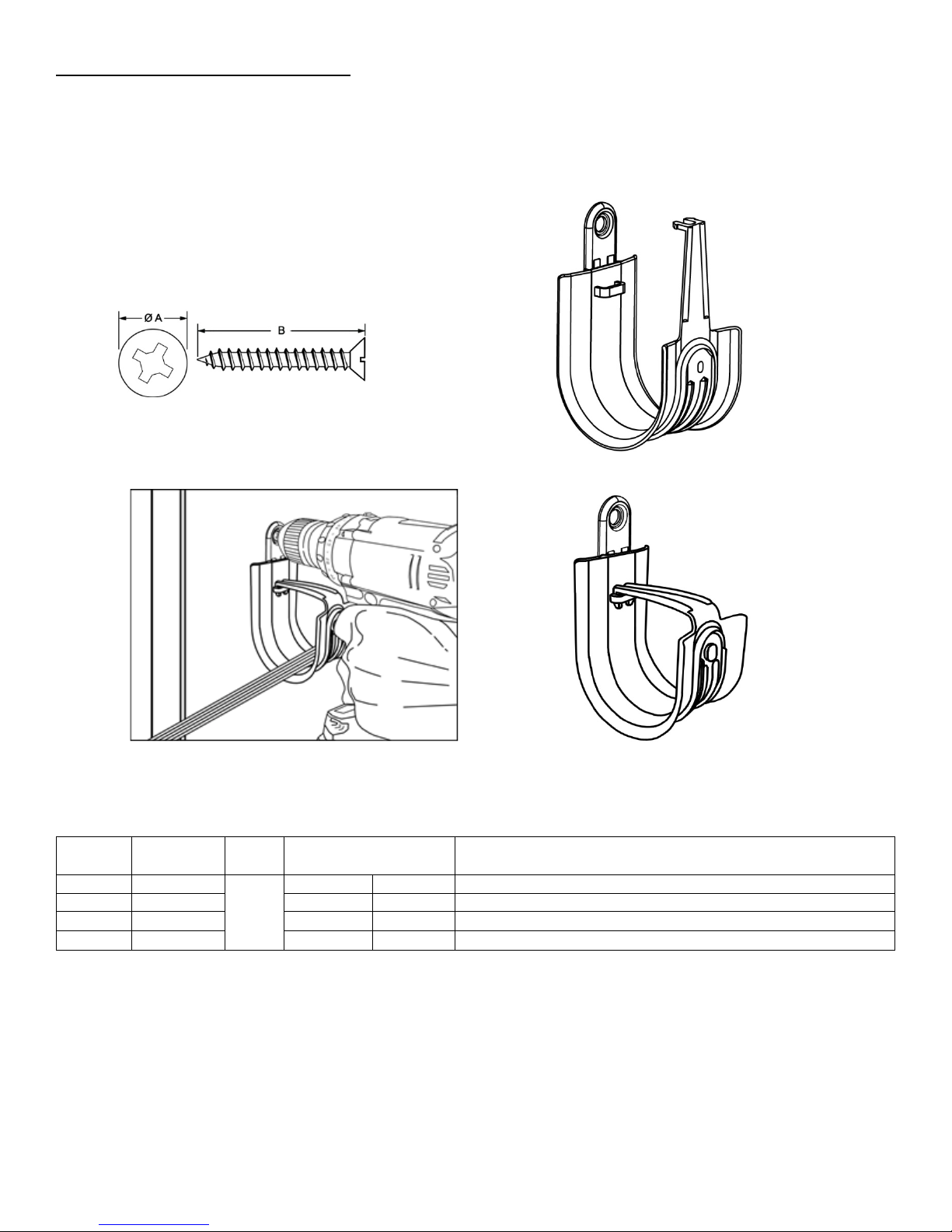
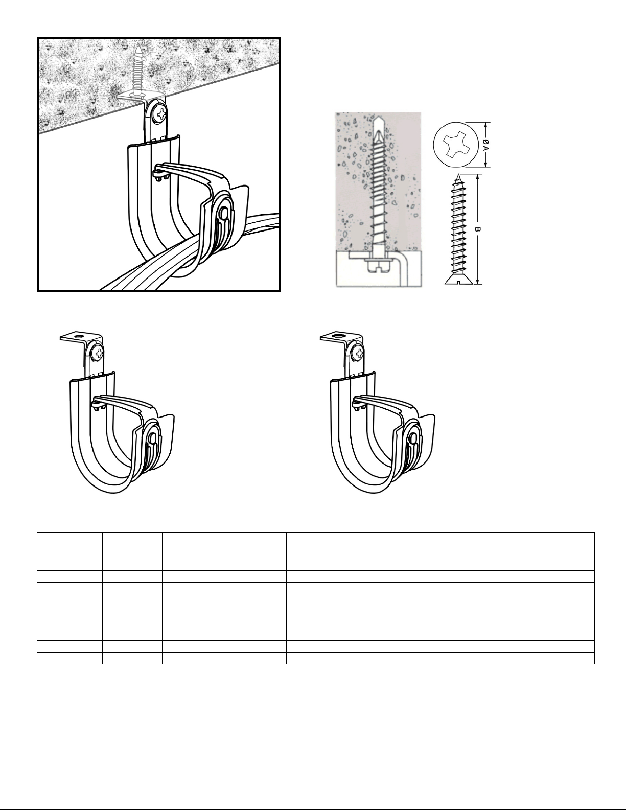
may be fastened directly to the underside of a horizontal surface using an appropriate fastener*
(Fig.6). Use a fastener with an appropriate head diameter (Fig.7-A) and an appropriate length
for the substrate (Fig.7-B). Place the cables in the hook and close the latch as shown in Fig.5
and Fig.6. The latch must be in the closed position as shown in Fig.8 and Fig.9 to secure the
cables and complete the installation.
Fig.1 Fig.2 Fig. 3
Fig. 4Fig. 5
6
Fig. 6 Fig. 7
Fig. 8 Fig. 9
Part No.
Hook
Size
Fig.
No.
UL Load
Rating
LBS. | N
Angle Clip
Hole Size
Description
HPH16AC
1"
1
20
88.96
1/4"
1” 90° Angle HPH J-Hook, size 16
HPH16AC6
1”
2
20
88.96
3/8”
1” 90° Angle/6 HPH J-Hook, size 16
HPH32AC
2”
1
20
88.96
1/4"
2” 90° Angle HPH J-Hook, size 32
HPH32AC6
2”
2
20
88.96
3/8”
2” 90° Angle/6 HPH J-Hook, size 32
HPH48AC
3”
1
20
88.96
1/4"
3” 90° Angle HPH J-Hook, size 48
HPH48AC6
3”
2
20
88.96
3/8”
3” 90° Angle/6 HPH J-Hook, size 48
HPH64AC
4”
1
20
88.96
1/4"
4” 90° Angle HPH J-Hook, size 64
HPH64AC6
4”
2
20
88.96
3/8”
4” 90° Angle/6 HPH J-Hook, size 64
7
Mounting to a horizontal surface with an Angle Clip 90° w/Powder Actuated Nail
(PAN):HPH16ACPA, HPH32ACPA, HPH48ACPA and HPH64ACPA
Use a powder actuated tool* to install the 1-5/16” pin into an appropriate material such as
concrete as shown in Fig. 3 & 4.
Fig.1 Fig.2
Fig.3 Fig.4
Part No.
Hook
Size
Fig.
No.
Load Rating
LBS. | N
Description
HPH16ACPA
1"
1
&
2
20
88.96
1” 90° Angle w/PAN HPH J-Hook, size 16
HPH32ACPA
2”
20
88.96
2” 90° Angle w/PAN HPH J-Hook, size 32
HPH48ACPA
3”
20
88.96
3” 90° Angle w/PAN HPH J-Hook, size 48
HPH64ACPA
4”
20
88.96
4” 90° Angle w/PAN HPH J-Hook, size 64
8
Mounting to a beam with an HOK24 or HOK58 Hammer-On Beam Clamp:HPH16HOK24,
HPH16HOK58, HPH32HOK24, HPH32HOK58, HPH48HOK24, HPH48HOK58,
HPH64HOK24 and HPH64HOK58
Secure a Hammer-On Beam Clamp to a flange using a hammer as shown in Fig. 5 & Fig. 6
below.
Note: The HOK-24 is designed for flanges from 1/8” to 1/4" thick; the HOK-58 is designed for
flanges from 5/16” to 1/2" thick.
Fig.1 Fig.2 Fig.3 Fig.4
Part No.
Hook
Size
Fig.
No.
UL Load
Rating
LBS. | N
Designed
for flanges
Description
HPH16HOK24
1"
1 & 2
20
88.96
1/8” - 1/4"
1” Hammer-On HPH J-Hook, 1/8”-1/4” flange, size 16
HPH16HOK58
1”
3 & 4
20
88.96
5/16 - 1/2”
1” Hammer-On HPH J-Hook, 5/16”-1/2” flange, size 16
HPH32HOK24
2”
1 & 2
17
75.62
1/8” - 1/4"
2” Hammer-On HPH J-Hook, 1/8”-1/4” flange, size 32
HPH32HOK58
2”
3 & 4
17
75.62
5/16 - 1/2”
2” Hammer-On HPH J-Hook, 5/16”-1/2” flange, size 32
HPH48HOK24
3”
1 & 2
20
88.96
1/8” - 1/4"
3” Hammer-On HPH J-Hook, 1/8”-1/4” flange, size 48
HPH48HOK58
3”
3 & 4
20
88.96
5/16 - 1/2”
3” Hammer-On HPH J-Hook, 5/16”-1/2” flange, size 48
HPH64HOK24
4”
1 & 2
17
75.62
1/8” - 1/4"
4” Hammer-On HPH J-Hook, 1/8”-1/4” flange, size 64
HPH64HOK58
4”
3 & 4
17
75.62
5/16 - 1/2”
4” Hammer-On HPH J-Hook, 5/16”-1/2” flange, size 64
Fig.5 Fig.6
9
Mounting to a beam with an FM24 or FM58 Hammer-On Beam Clamp:HPH16ACFM24,
HPH16ACFM58, HPH32ACFM24, HPH32ACFM58, HPH48ACFM24, HPH48ACFM58,
HPH64ACFM24
and HPH64ACFM58
Secure a knock-on beam clamp to a flange using a hammer as shown in Fig. 5 & Fig. 6 below.
Note: The ACFM24 is designed for flanges from 1/8" to 1/4" thick. The ACFM58 is designed for
flanges from 5/16" to 1/2" thick. Both the ACFM24 & ACFM58 can be rotated 360°.
Fig.1 Fig.2 Fig.3 Fig.4
Fig.5 Fig.6
Part No.
Hook
Size
Fig.
No.
UL Load
Rating
LBS. | N
Designed for
flanges
Description
HPH16ACFM24
1"
1 & 2
20
88.96
1/8” - 1/4"
1” Hammer-On HPH J-Hook, Swivels 360°, 1/8”-1/4”
Flange, size 16
HPH16ACFM58
1”
3 & 4
20
88.96
5/16 - 1/2”
1” Hammer-On HPH J-Hook, Swivels 360°, 5/16” – 1/2"
Flange, size 16
HPH32ACFM24
2”
1 & 2
20
88.96
1/8” - 1/4"
2” Hammer-On HPH J-Hook, Swivels 360°, 1/8”-1/4”
Flange, size 32
HPH32ACFM58
2”
3 & 4
20
88.96
5/16 - 1/2”
2” Hammer-On HPH J-Hook, Swivels 360°, 5/16” – 1/2"
Flange, size 32
HPH48ACFM24
3”
1 & 2
20
88.96
1/8” - 1/4"
3” Hammer-On HPH J-Hook, Swivels 360°, 1/8”-1/4”
Flange, size 48
HPH48ACFM58
3”
3 & 4
20
88.96
5/16 - 1/2”
3” Hammer-On HPH J-Hook, Swivels 360°, 5/16” – 1/2"
Flange, size 48
HPH64ACFM24
4”
1 & 2
20
88.96
1/8” - 1/4"
4” Hammer-On HPH J-Hook, Swivels 360°, 1/8”-1/4”
Flange, size 64
HPH64ACFM58
4”
3 & 4
20
88.96
5/16 - 1/2”
4” Hammer-On HPH J-Hook, Swivels 360°, 5/16” – 1/2"
Flange, size 64
10
Mounting to a beam with a BC Beam Clamp:HPH16BC, HPH16ACBC, HPH32BC,
HPH32ACBC, HPH48BC, HPH48ACBC, HPH64BC and HPH64ACBC
Secure a screw-on beam clamp to a flange using a 3/8” socket driver or wrench as shown in
Fig.5, 6, 7, & 8 below. Tighten the bolt to 20 in-lb.
Note: The BC & ACBC’s are designed for flanges up to 1/2" thick. The ACBC can be rotated 360°.
Fig.1 Fig.2 Fig.3 Fig.4
Part No.
Hook
Size
Fig.
No.
UL Load
Rating
LBS. | N
Designed
for
flanges
Description
HPH16BC
1"
1 & 2
20
88.96
1/8” - 1/2"
1” Beam Clamp HPH J-Hook, Size 16
HPH16ACBC
1”
3 & 4
20
88.96
1” Swivel 360° Beam Clamp HPH J-Hook, size 16
HPH32BC
2”
1 & 2
17
75.62
2” Beam Clamp HPH J-Hook, Size 32
HPH32ACBC
2”
3 & 4
20
88.96
2” Swivel 360° Beam Clamp HPH J-Hook, size 32
HPH48BC
3”
1 & 2
20
88.96
3” Beam Clamp HPH J-Hook, Size 48
HPH48ACBC
3”
3 & 4
20
88.96
3” Swivel 360°Beam Clamp HPH J-Hook, size 48
HPH64BC
4”
1 & 2
17
75.62
4” Beam Clamp HPH J-Hook, Size 64
HPH64ACBC
4”
3 & 4
20
88.96
4” Swivel 360° Beam Clamp HPH J-Hook, size 64
Fig.5 Fig.6