manuals.online logo
Brands
  1. Home
  2. •
  3. Brands
  4. •
  5. Pluribus Networks
  6. •
  7. Switch
  8. •
  9. Pluribus Networks F9372-T User manual

Pluribus Networks F9372-T User manual

–1–
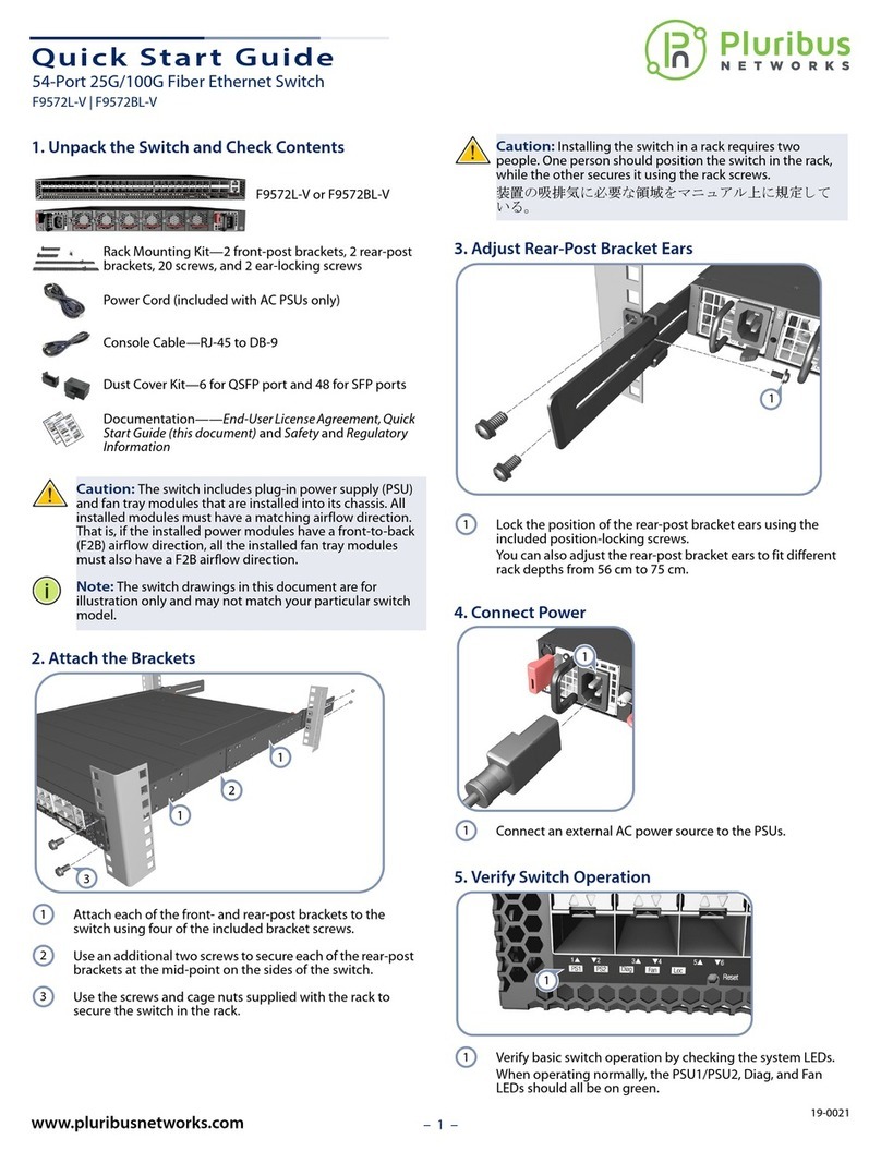
1. Unpack the Switch and Check Contents
10G Copper Ethernet
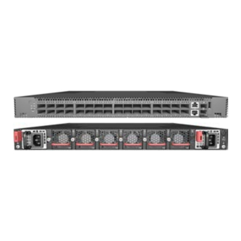
Switch
F9372-T
F9372B-T
2 front-post brackets
2 rear-post brackets with adjustable ears
20 bracket screws
2 rear bracket ear position-locking screws
Power Cords
Console Cable—RJ-45 to DB-9
Documentation—End-User License Agreement, Quick
Start Guide(this document) and Safety and Regulatory
Information
Caution:
The switch includes two plug-in AC PSUs and ve
fan tray modules that are installed into its chassis. All
installed modules must have a matching airow direction.
That is, all modules must have a front-to-back (F2B) airow
direction, or all modules must have a back-to-front (B2F)
airow direction. The airow direction of PSU and fan tray
modules is indicated by labels on the modules.
2. Attach the Brackets
Attacheachof the two front-post brackets to the front of the
switch using four of the included bracket screws.
Attach each of the two rear-post brackets to the rear of the
switch using four of the included bracket screws.
For the rear-postbrackets, use an additional two bracket
screws to secure the bracket at the mid-point on the side of
the switch.
1
2
3
1
2
3
3. Mount the Switch
Caution:
Installing the switch in a rack requires two people.
One person should position the switch in the rack, while the
other secures it using the rack screws.
As per your rack plan, mark the holes in the rack where you
want to install the switch.
Lift the switch into the rack and align it with the marked
holes.
Secure the front-post brackets to the rack using four screws
and cage nuts supplied with the rack.
4. Adjust Rear-Post Bracket Ears
Adjust the rear-post bracket ears to t the depth of the rack.
Secure the rear post brackets to the rack rear posts using
four screws and cage nuts supplied with the rack.
Lock the position of the rear-post bracket ears using the
included position-locking screws.
1
2
3
1
2
3
3
2
1
1
2
3
E102016-AP-R01
150200001606A
54-Port 10G Copper Ethernet Switch
Quick Start Guide
F9372-T | F9372B-T
www.pluribusnetworks.com
– 2 –
5. Connect Power
Connect an external AC power source to the PSUs.
6. Verify Switch Operation
Verify basic switch operation by checking the system LEDs.
When operating normally, the PSU1/PSU2, Diag, and Fan
LEDs should all be on green.
7. Configuring the switch
Toconfigure your switch please refer to the Pluribus Networks
Quick Start Guide available at this location:
http://www.pluribusnetworks.com/get-started/
8. View the Product Label
The switch product label is located below RJ-45 ports 7–12
on left side of the front panel. Pull the label out to view the
product information.
1
1
1
1
1
Hardware Specifications
Switch Chassis
Size (WxDxH) 442.5 x 473 x 43.95 mm (17.42 x 18.62 x 1.73 inches)
Weight 9.41kg (20.74 lb), with two installed PSUs
Temperature Operating: 0° C to 40° C (32° F to 104° F)
Storage: -40° C to 70° C (-40° F to 158° F)
Humidity Operating: 5% to 95% (non-condensing)
Power
Consumption 384 Watts maximum
AC PSU
Power Rating 100–240 VAC, 50-60 Hz, 400 Watts
AC Input 100–240 VAC, 50-60 Hz, 6–3 A
DC Output 5 VDC @ 3 A, 12 VDC @ 33 A
Regulatory Compliances
Emissions EN 55032:2012/AC:2013, Class A
EN 61000-3-2:2014
EN 61000-3-3:2013
FCC Class A
VCCI Class A
CE Mark
BSMI EMI Standard CNS 13438:2006
Immunity EN 55024:2010
IEC 61000-4-2:2008
IEC 61000-4-3:2006/A1:2007/A2:2010
IEC 61000-4-4:2012
IEC 61000-4-5:2014
IEC 61000-4-6:2013
IEC 61000-4-8:2009
IEC 61000-4-11:2004
Safety UL (CSA 22.2 No 60950-1 & UL60950-1)
CB (IEC/EN60950-1)
BSMI Safety Standard CNS14336-1
Quick Start Guide
– 3 –
1. 拆開交換器包裝並檢查內容物
10G 乙太網路交換器
F9372-T
F9372B-T
2個前柱托架
2個後柱托架,附可調式固定片
20 個托架螺絲。
2個後方托架固定片定位螺絲
電源線
注意:
交換器包含兩個插入式 AC 電源供應器以及 5
個風扇托盤 模組。所有已安裝之模組氣流方向,必須一
致。意即,所有模組的氣流方向必須為由前至後
(F2B),或者必須為由後至前 (B2F)。
2.安裝托架
利用四個所附之托架螺絲,將兩個前柱托架安裝在交換
器前方。
利用四個所附之托架螺絲,將兩個後柱托架安裝在交換
器後方。
針對後柱托架,額外使用兩個托架螺絲,將托架固定在
交換器側邊中間處。
1
2
3
1
2
3
3.安裝交換器
注意:
需要兩個人,將交換器裝到機櫃上。一人負責固
定交換器在機櫃上之位置,另一人負責用機櫃螺絲固
定。
依據您的機櫃配置,標出欲安裝交換器之機櫃孔位置。
將交換器放到機櫃中,對齊標示孔。
利用隨機櫃所附之四個螺絲及籠罩螺帽,將前柱托架固
定在機櫃上。
4.調整後柱托架固定片
調整後柱托架固定片,以符合機櫃深度。
利用隨機櫃所附之四個螺絲及籠罩螺帽,將後柱托架固
定在機櫃上。
利用所附的定位螺絲,鎖緊後柱托架固定片位置。
1
2
3
1
2
3
3
2
1
1
2
3
54 埠10G 乙太網路交換器
快速入門指南
F9372-T | F9372B-T
– 4 –
5. 連接電源
將外部 AC 電源連接至模組。
6. 確認交換器操作
透過檢查系統 LED,確認交換器的基本運轉情況。如運
轉正常,PSU1/PSU2、Diag 和風扇 LED 會亮起綠燈。
7. 設定交換器
要設定交換器,請參閱此網址提供的 Pluribus Networks 快速入
門指南,http://www.pluribusnetworks.com/onvl-get-started/ 。
8. 檢視產品標籤
交換器產品標籤,位於 RJ-45 連接埠 7-12 下方、前方面
板左側。拉出標籤即可檢視產品資訊。
1
1
1
1
1
硬體規格
交換器機箱
尺寸
(WxDxH)
438.4 x 473 x 43.4 mm (17.26 x 18.62 x 1.71 英
吋)
重量 9.41 kg (20.74 lb),含兩個安裝之 PSU
溫度 操作 : 0° C ~ 40° C (32° F ~ 104° F)
儲存 : -40° C ~ 70° C (-40° F ~ 158° F)
濕度 操作 : 5% ~ 95% (無冷凝)
消耗功率 最大 282 瓦
AC PSU
額定功率 100–240 VAC,50-60 Hz,400 瓦
AC 輸入 100–240 VAC, 50-60 Hz, 6–3 A
DC 輸出 5 VDC @ 3 A, 12 VDC @ 33 A
法規符合性
排放 EN 55032:2012/AC:2013, Class A
EN 61000-3-2:2014
EN 61000-3-3:2013
FCC Class A
VCCI Class A
CE Mark
BSMI EMI Standard CNS 13438:2006
電磁耐受性 EN 55024:2010
IEC 61000-4-2:2008
IEC 61000-4-3:2006/A1:2007/A2:2010
IEC 61000-4-4:2012
IEC 61000-4-5:2014
IEC 61000-4-6:2013
IEC 61000-4-8:2009
IEC 61000-4-11:2004
安全性 UL (CSA 22.2 No 60950-1 & UL60950-1)
CB (IEC/EN60950-1)
BSMI Safety Standard CNS14336-1
快速入门指南

Other manuals for F9372-T

1

This manual suits for next models

1

Other Pluribus Networks Switch manuals
Pluribus Networks F9572-V User manual

Pluribus Networks

Pluribus Networks F9572-V User manual

Pluribus Networks F9432-C User manual

Pluribus Networks

Pluribus Networks F9432-C User manual

Pluribus Networks F9572L-V User manual

Pluribus Networks

Pluribus Networks F9572L-V User manual

Pluribus Networks F9372-T User manual

Pluribus Networks

Pluribus Networks F9372-T User manual
Pluribus Networks Freedom Series User manual

Pluribus Networks

Pluribus Networks Freedom Series User manual

Pluribus Networks F9272-X User manual

Pluribus Networks

Pluribus Networks F9272-X User manual

Pluribus Networks F9532L-C User manual
Pluribus Networks

Pluribus Networks F9532L-C User manual

Popular Switch manuals by other brands

Digitus DS-12901 Quick installation guide

Digitus

Digitus DS-12901 Quick installation guide

Sony MK7807V1 Guide book

Sony

Sony MK7807V1 Guide book

Hitachi SB-1 user manual

Hitachi

Hitachi SB-1 user manual

Barco PresentationPRO-II user guide

Barco

Barco PresentationPRO-II user guide

axing Basic Series Operation instructions

axing

axing Basic Series Operation instructions

ABB Ekip CI manual

ABB

ABB Ekip CI manual

WideSky Hub 1P-AC installation guide

WideSky

WideSky Hub 1P-AC installation guide

TRENDnet TEG-S18TX Specifications

TRENDnet

TRENDnet TEG-S18TX Specifications

Motorola RFS7000 Series reference guide

Motorola

Motorola RFS7000 Series reference guide

Bay Networks 8000 RAC Installing manual

Bay Networks

Bay Networks 8000 RAC Installing manual

Vesternet VES-ZB-SWI-005 quick start guide

Vesternet

Vesternet VES-ZB-SWI-005 quick start guide

Compaq Storageworks SAN Switch 16 Installation and hardware guide

Compaq Storageworks

Compaq Storageworks SAN Switch 16 Installation and hardware guide

SNR SNR-S212i-8POE Series installation guide

SNR

SNR SNR-S212i-8POE Series installation guide

Belden HIRSCHMANN MSP30 user manual

Belden

Belden HIRSCHMANN MSP30 user manual

Contemporary Controls CTRLink EISK8P-GT installation guide

Contemporary Controls

Contemporary Controls CTRLink EISK8P-GT installation guide

3Com 3CNJ220-CRM datasheet

3Com

3Com 3CNJ220-CRM datasheet

Uptime Devices Sensor Hub quick start guide

Uptime Devices

Uptime Devices Sensor Hub quick start guide

Leonton PT2-0500-24 Series user manual

Leonton

Leonton PT2-0500-24 Series user manual

manuals.online logo
manuals.online logoBrands
  • About & Mission
  • Contact us
  • Privacy Policy
  • Terms and Conditions

Copyright 2025 Manuals.Online. All Rights Reserved.