ROBOTIQ FT 300-S User manual

robotiq.com | leanrobotics.org
Original Notice
© 2021Robotiq Inc.
Robotiq FT 300-S Force Torque
Sensor for OMRON TM Series Robots

Table of Contents
Revisions 4
1. GeneralPresentation 6
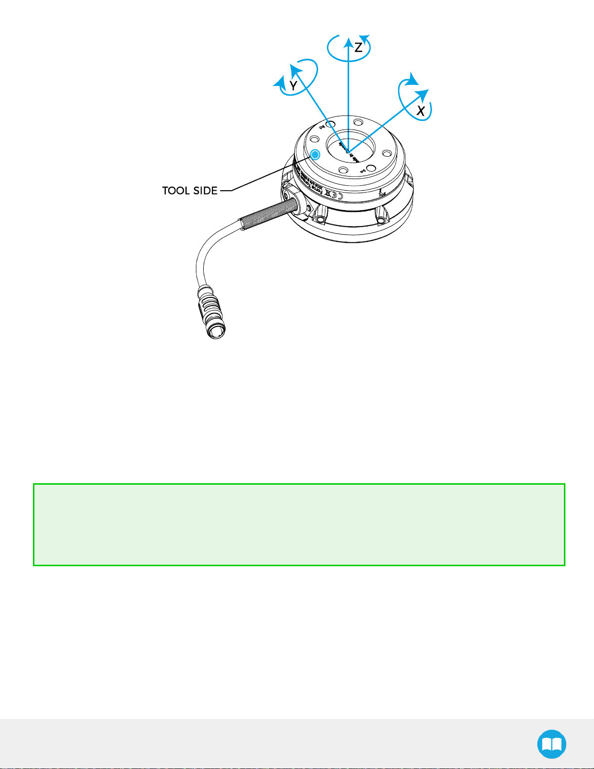
1.1. FT300-SForce TorqueSensor 6
2. Safety 9
2.1. Warning 10
2.2. Intended Use 11
3. Installation 12
3.1. Scope of Delivery 12
3.2. Environmentaland Operating Conditions 13
3.3. MechanicalInstallation 14
3.4. PowerSupplySpecifications 16
3.5. Wiring 17
3.6. CalibrationProcedure forVisualDemo Software (PC) 20
4. Software 21
4.1. Use inTMFlowSoftware 21
4.2. Development Package 25
4.3. VisualDemo Software 29
4.4. SerialCommunication 30
5. Specifications 36
5.1. TechnicalDimensions 36
5.2. MechanicalSpecifications 38
5.3. SignalSpecifications 41
5.4. ElectricalRatings 42
5.5. Couplings 42
6. Maintenance 44
6.1. Maintenance Intervals 44
6.2. Cable replacement procedure 45
7. Spare Parts, Kitsand Accessories 46
8. Troubleshooting 47
FT 300-SForceTorqueSensor-InstructionManual
2

FT 300-SForceTorqueSensor-InstructionManual
3
8.1. Generaltroubleshooting 47
8.2. Troubleshooting onotherplatforms 48
9. Harmonized Standards, Declarationsand Certificates 49
9.1. OriginalEU Declarationof Conformity 49
9.2. Applied standards 50
9.3. IngressProtectionCertification 51
10. Warranty 53
10.1. Exclusions 53
11. Contact 55

FT 300-SForceTorqueSensor-InstructionManual
4
Revisions
Robotiq may modify this product without notice, when necessary, due to product improvements, modifications or changes in
specifications. If such modification is made, the manual will also be revised, see revision information. See the latest version of this
manual onlineat:support.robotiq.com.
2021-03-01
lUpdateof the FT 300Torque Sensorwhich isnowthe FT 300-STorque Sensorwith anewdesign.Varioussectionsof thisinstruc-
tion manual have beenupdated relatively to thismechanical change.For all information about theFT 300Torque Sensor,please
consult the Archivessectionat support.robotiq.com.
Revision2020/04/06
Section3updated.
Revision2019/06/21
Section3,4and 8updated.
Revision2019/04/30
Initial release

FT 300-SForceTorqueSensor-InstructionManual
5
Copyright
© 2021Robotiq Inc.All rightsreserved.
Thismanual and theproduct it describesareprotected bytheCopyright Act of Canada,bylawsof othercountries,and by
international treaties,and thereforemaynot bereproduced in wholeorinpart,whetherfor saleornot,without priorwrittenconsent
from Robotiq.Undercopyright law,copying includestranslation into another languageorformat.
Information provided byRobotiq inthisdocument isbelieved to beaccurateand reliable.However,no responsibilityisassumed
byRobotiq foritsuse.Theremaybesomedifferencesbetweenthemanualand theproduct if theproduct hasbeenmodified after
theeditiondate.
Theinformationcontained in thisdocument issubject to changewithout notice.

1.General Presentation
Theterms''Sensor'',''Robotiq Sensor'',''ForceSensor'',''TorqueSensor'',''FT 300-SForceTorqueSensor'' used inthefollowing
manual referto the Robotiq FT 300-SForceTorqueSensorunlessspecified.TheRobotiq FT 300-SForceTorqueSensorisa
roboticperipheral designed forforce and torquedataacquisition.
Info
Thefollowing manual usesthemetricsystem.Unlessspecified,alldimensionsareinmillimeters.
1.1.FT300-SForce Torque Sensor
Info
Thefollowing sectionpresentskeyfeaturesof theSensor,and must not be considered asbeing related to Sensor
operation.Everyfeatureisdetailed intheapplicablesectionof themanual.Safetyguidelinesmust beread and
understood beforeanyoperationisattempted with the Sensor.
TheForce TorqueSensorisaroboticperipheral designed for force and torquedataacquisitiononrobots.It isinstalled on the
robot tool flangewith amechanical coupling.A sensorcable (not shown)isused forpowerand communications.
Fig. 1.1:FT 300-SForce Torque Sensor Nomenclature
FT 300-SForceTorqueSensor-InstructionManual
6

FT 300-SForceTorqueSensor-InstructionManual
7
1.1.1.Mainfeatures
Fig.1.2:Overviewof theRobotiq ForceTorqueSensors,withmain features.
lTheend-of-armtool contact surface (ingreen)istheonlypoint of contact allowed betweentheSensor and thetool to ensure
correct forceand torquefeedback.
lTherobot contact surface(inblue)istheonlycontact point allowed betweentheSensorand therobot forfastening thesensor
to therobot.Notethat theinsidering must not touchtherobot.
lToolPlateisnot shown,but might be required whencertainend-of-arm toolsaremounted ontheFT 300ForceTorque
Sensor.
Info
Detailsonthebolt patternand indexing pin forthetoolsideand the robot sidecanbefound intheSpecifications
section.
lM12connectorallowsfor bothpowerand datatransferfortheSensor.
lStatusLED providesvisual informationon the statusof theSensor,see Installationsection.

FT 300-SForceTorqueSensor-InstructionManual
8
Fig.1.3:FT 300-SForceTorqueSensorforceand torquediagrams.
Thefigureaboverepresentsthevariousforceand torquesthat the FT 300-SForceTorqueSensorcanmeasure.Referenceframe is
centered ontheSensorasshown aboveand visual inscriptionsarealso represented onit.
lTheZaxispassesthrough the centerof thedepressionwithpositive directioninthetool direction.
lThe Xaxistraces asymmetriclinecentered ontheconnector;thepositive direction pointstheoppositeway awayfrom the con-
nector.
lTheYaxisusestheright hand thumb ruleaccording to X-Z.
Tip
It isimportant to understand that the FT 300-SForceTorqueSensorcanbeused eitherasaModbusRTUslaveorasa
streaming device.When useasaslave unit you will send statusrequests(read function)to get theforce & moment
values,while whenin data stream modetheSensorwill continuouslystream data without responding to amaster
request.Pleasereferto theSerialCommunicationsectionfordetails.

2.Safety
Warning
Theoperator must haveread and understood all theinstructionsin thismanual before handling theRobotiq Force
TorqueSensor.
Info
The term "operator" refersto anyone responsible for:
Anyof thefollowing operationswith theFT 300and the associated robot ortools:
lInstallation
lControl
lMaintenance
lInspection
lDecommissioning
Thisdocumentation explainsthevariouscomponentsof theForceTorqueSensor,aswell asgeneral operationsregarding the
whole life-cycle of the product from installationto operation and decommissioning.
Thedrawingsand photosinthisdocumentationarerepresentativeexamplesand differencesmayexist betweenthem and the
delivered product.
FT 300-SForceTorqueSensor-InstructionManual
9

FT 300-SForceTorqueSensor-InstructionManual
10
2.1.Warning
Info
Anyuse of theForceTorqueSensorinnoncomplianceof thesewarningsisinappropriateand maycause injuryor
damage.
Warning
A force torque sensorused in human-robot collaborationmust not beconsidered acompletesafetymeasure,additional
dedicated safetydevice(s)must beconsidered.Sensorfailurecanoccurand result indangerforworkersormachinery.
Seelocal orinternational safetymeasureforhuman-robot collaboration.
Warning
lTheSensorneedsto be properlysecured beforeoperating therobot.
lDo not install oroperate aSensorthat isdamaged orlacking parts.
lNeversupplytheSensorwithanalternativecurrent source.
lMake sureall cord setsarealwayssecured at bothends,at theSensorand at therobot.
lAlwaysmeet therecommended keying forelectrical connections.
lMake sureno oneisintherobot and/orSensorpathbeforeinitializing therobot'sroutine.
lAlwaysmeet the Sensorpayload specifications.
lAll local safetymeasuresand/orlawsonrobot operation must be applied to theSensor.
lAnyuse of theSensorinnoncompliancewiththesewarningsisinappropriateand maycause injuryordamage.

FT 300-SForceTorqueSensor-InstructionManual
11
2.2.Intended Use
The Sensor isdesigned fordata acquisition(force and torquesensing)for an end-of-arm tool on arobot.
TheSensorisintended forinstallationonarobot orotherautomated machineryorequipment.
Thesoftwareisused forthe implementation of aforce torquesensor'soperational commandsin auserinterface.
Info
Alwayscomplywithlocal and/ornational laws,regulationsand directivesonautomationsafetyand generalmachine
safety.
Theunit maybeused onlywithintherangeof itstechnical specifications.Anyotheruse of theproduct isdeemed improper and
unintended use.Robotiq will not beliableforanydamagesresulting from anyimproper orunintended use.

3.Installation
Warning
Besureto read and understand thesafetyinstructionsrelated to theRobotiq ForceTorqueSensorpriorto installation.
3.1.Scope of Delivery
Standard deliveryfor an FT Sensor kit:
FTS-300-S-OMRON-KIT
FT-300-SBasicSensorUnit (FTS-300-S-SEN-001)
1xMechanical coupling (FTS-300-S-CPL-014)
1 x10m High-FlexCable(straight connector)(CBL-COM-2073-10-HF)
1xUSBto RS485Adapter(ACC-ADT-USB-RS485)
1XRS232to RS485adapter(ACC-ADT-RS232-RS485)
1xUSBStick(ACC-USB-16G)
FT 300-SForceTorqueSensor-InstructionManual
12

FT 300-SForceTorqueSensor-InstructionManual
13
3.2.Environmental and OperatingConditions
TheFT 300-SForceTorqueSensorisdesigned forindustrial applications.Alwaysrespect thefollowing specified storage,transport
and operating environmental conditions:
CONDITION VALUE
Minimum storage/transit
temperature -30°C
Maximum storage/transit
temperature 70°C
Minimum operating temperature15°C
Maximum operating temperature140°C
Humidity(non-condensing) 20-80%RH
Maximum vibration (storage/
transit) 5G
Maximum vibration (operating) 2G
IPrating IP652,3
Other lFreefrom corrosive liquidsorgases
lFree from explosive liquidsorgases
lFree from powerful
electromagnetic interference
1Refer to the Signal Specifications section for details on temperature compensation range.
2Dust-tight and protected against water jets .
3IPCertification performed on the FT 300-S-UR-KIT, FT 300-S-OMRON-KIT, and FT 300-S-TM-KIT configurations only.

FT 300-SForceTorqueSensor-InstructionManual
14
3.3.Mechanical Installation
Youmust useacoupling to attachtheSensorto arobot.Besureto usethecoupling related to yourrobot model.
Herearethestepsto followfortheinstallationof theSensor(seefiguresbelow).
1. Place theprovided dowel pin intherobot tool flangeholethat isnear the camera.
2. Mount themechanical coupling onyourrobot arm.Alignmarked hole 2with thedowel pin.
3. Securebyinserting theM6screwsand toothlockwashers
4. Mount theForce TorqueSensoronthemechanical coupling.
5. Securebyinserting theM4screwsand theBellevillewashers(withtheconvexsideupward)ina crosspatternto properlycom-
presstheO-ring.

FT 300-SForceTorqueSensor-InstructionManual
15
Fig. 3.1:Attaching the FT 300-Ssensorto a robot arm using themandatorycoupling.

FT 300-SForceTorqueSensor-InstructionManual
16
3.4.PowerSupplySpecifications
TheSensorneedsto besupplied bya DCvoltagesource.Thispowersupplyisnot included withtheSensor.
POWERSUPPLYSPECIFICATIONS VALUE
Output voltage 5to 24 VDC
Maxpower consumption 2W
Overcurrent 1A Fuse (Phoenix#0916604(UT6-TMCM 1A))
Overvoltageprotection Warning
Maximum output voltagetolerance is10%,exceeding this
limit,26.4VDCcould damagetheSensor.
Info
Robotiq recommendstheuseof thefollowing powersupply:
TDK-LambdaDPPSeries,15W SingleOutput DIN Rail Mount PowerSupply,DPP15-24

FT 300-SForceTorqueSensor-InstructionManual
17
3.5.Wiring
Powerand communicationsareestablished withtheFT 300-SForceTorqueSensorviaasingle devicecable.TheFT 300hasa
pigtail cable.
ThefigurebelowrepresentstheFT 300-SForceTorqueSensorreceptacle(Sensorside)and connector(cableside)withassociated
pinout.TheM12- 5pinA-coded connector isused inaccordance withIEC61076-2-101.
Warning
Use propercabling management.Be sureto haveenoughforgivenessinthecabling to allowmovement of theGripper
along all axeswithout pulling out theconnectors.Alwaysprotect thecontrollerside of thecable connection withastrain
relief cable clamp.
Fig.3.2:Pinout of theRobotiq FT 300-SForce TorqueSensorand colorcodepercabletype.
Info
Powerpins2 & 3are connected to thespecified powersupply.
Info
RS-485signal pins1,4& 5are connected directly,to aRS-485/ USBconverterorto a RS-485/ RS-232converter.

FT 300-SForceTorqueSensor-InstructionManual
18
Fig.3.3:FT300-SCableto Terminal Connector ontheController
3.5.1.Wiringwith USBtoRS485 Converter
Whenusing aRS485to USBconverter(referto theSpare Parts,Kitsand Accessoriessection),thewiring must respect thefigure
belowand subsequent directions.GND / 0Viswired to Sensorpin#1asstated intheWiring section.
Theconverterwill provideyouwithastandard USB2.0maleA connector.
Fig. 3.4:Wiring diagram for theRS485 to USBconverter
Warning
Powerisnot delivered viatheUSB,do not plug 24Vinto theUSB.
3.5.2.WiringwithRS232toRS485Converter
Whenusing aRS232to RS485converter(referto theSpare Parts,Kitsand Accessoriessection),thewiring must respect thefigure
below.

FT 300-SForceTorqueSensor-InstructionManual
19
Warning
Do not wireconverterpin#3(5V)ontheRS485.
The 24VpowersupplyisNOT supplied via theconverter.
Theconverted sidewill provide youwithastandard DB-9female connector withsignaling asshowninthe figurebelow.
Fig. 3.5:Wiring diagram for RS232to RS485 converter.

FT 300-SForceTorqueSensor-InstructionManual
20
3.6.CalibrationProcedure for Visual Demo Software (PC)
Info
You need theVisual Demo Softwareinstalled first.Pleasereferto theVisualDemo Software sectionfordownload and
installation.
To calibrateyourFT 300-SSensor:
1Go to the "Tool Calibration" tab and followtheinstructions.
2 Oncecompleted,go to the"SensorData" tab.
Other manuals for FT 300-S
2
Table of contents
Other ROBOTIQ Accessories manuals