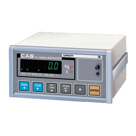
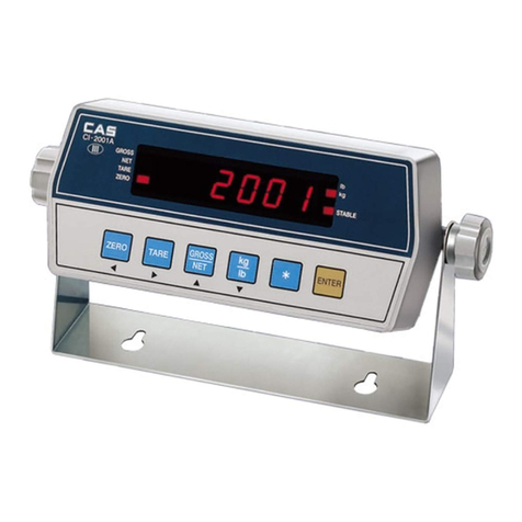
CAS CI-502A User manual

`
2

`
3
Contents
Precautions for Safety ........................................................... 4
Features and Main functions............................................... 7
Technical Specification.......................................................... 8
ExternalAppearance and Dimensions............................10
Front Panel Descriptions....................................................12
Rear Panel Descriptions......................................................17
Installation & Connection..................................................18
Calibration Mode.................................................................20
Weighing Mode.....................................................................26
Test Mode...............................................................................31
Set Mode.................................................................................35
Communication & Print Function...................................44
RS-232C Communication..................................................45
Set External Relay Input Function(Relay Function)....50
Option Series.........................................................................64
Hardware Set Function.......................................................65
Serial Communication(RS-232C).....................................66
Current loop..........................................................................69
RS-422/RS-485 Serial Communication...........................70
Sealing Method.....................................................................75

`
4
Precautions for Safety
Please comply with 'Cautions for Your Safety', which will lead you to use the product safely and
properly to prevent any dangerous situations.
■Cautions are divided into 'Warning' and 'Alert', which mean as follows.
■Keep this manual in a place where product users can find out, after finish reading it.
'Warning' means a great possibility led to the death or heavy injury when instructions are violated.
'Alert' means a great possibility led to the injury or material damage when instructions are violated.

`
5
Warning
When any damage or defect
occurs, contact your CAS
authorized dealer immediately
for proper repair.
Insert plug firmly to wall outlet to
prevent electric shock.
Scale must be grounded to
minimize electricity static. This
will minimize defect or electric
shock.
Do not pull the plug by its cord
when unplugging. Damaged
cord could cause electric shock
or fire.
To prevent from fire occurring,
Do not place or use the scale
near flammable or corrosive
gas.
To reduce electric shock or
incorrect reading, Do not spill
water on the scale or place it in
humid condition.
Avoid placing the scale near
heather or in direct sunlight.

`
6
Attention
For consistent and accurate
reading, maintain periodical
check by your CAS authorized
dealer.
Avoid sudden shock to the scale.
Internal mechanism could by
damaged.
Attach the rubber pad to the
bottom of the indicator.
Elimination is possible.
Place the scale on firm and
temperature consistent
environment.
Keep the scale away from the electromagnetic generation devices.
This may interfere with accurate reading.
Our Dealers : CAS feels that each of its valued customers should get the best service
available. Whether it’s the initial installation of our product,
maintenance/repair work, or simply answering questions about our products,
CAS Corporation and all of its Authorized Dealers are highly trained to assist
you with any need regarding CAS products.

`
7
Introduction
Thank you for purchasing our CAS Industrial Indicator.
This product has superior function and outstanding features from undergoing strict examinations
as well as our devotion to every detail under strict quality control.
CAS Indicator (CI-500A Series) is a product with diverse functions and various external
interface functions. It was designed to be suitable for specific requirements of a variety of
industrial sites, and its external design is based on both durability and beauty.
In addition, in order to make the Indicator easy to use for the users, it was programmed for the
convenient use of its users, and a message indicator function is internalized to help the
understanding of its user.
Thoroughly read this instruction manuarl before using our product, CI-501A series, and use it
accordingly in order to utilize it to its maximum potential.
Features and Main Functions
Features
■High-speed, High-accuracy Indicator for Industrial Use
■Suitable for measurement and weighing systems
■Easy to operate with diverse functions
■Simple Calibration (FULL DIGITAL CALIBRATION)
■Panel-type Indicator
■Shielded against RFI/EMI
■Self-diagnosis and self-recovery functions
■Data recovery function during blackouts (WEIGHT BACK-UP)
■A variety of options
Main Functions
■Saving of Date & time, and total data in case of blackouts,
■Adjustment of changing speed of weights (digital filter function)
■Connection to various types of printers (Serial)
-Sub total print function according to item and grand total function
-Built-in clock(RTC-Real Time Clock) allows print-out of weighing date and time
■PC communication function (PC Command mode)
■4 Built-in external relay input terminals
■6 Built-in external relay output terminals
■The user may set the desired maximum weight and the arbitrary value of 1 division
■Zero or span calibration may be operated separately
■Self-hardware test function
-Circuits can be tested according to modules; thus, repair services can be handled
immediately in case of problems
`
8
Technical Specification
■Analog Part & A/D Conversion
Input sensitivity 0.45㎶/ D
Adjustment range of Zero - 0.6mV + 42.0mV∼
Load Cell Excitation Voltage DC 10V (±5V)
Temperature Coefficient Zero: ±20 PPM / ℃
SPAN : ±20 PPM / ℃
Input Noise ±0.6㎶P. P
Input Impedance Over 10㏁
A/D conversion method ∆∑
A/D resolution 520,000 Count(19bit)
A/D conversion rate 200 times / sec
Nonlinearity 0.01% FS
■Digital Part
Span Calibration Full Digital Calibration
(Set one automatic weight calibration)
Display
7Segment 3 red-colored digits FND 2EA
CI-502A Character size : 20.0(H) X 11.0(W) mm
CI-505A Character size: 14.1(H) X 8.1(W) mm
Key Function key (4EA), Number and Function key (12 EA)
Division X1, X2, X5, X10, X20, X50
Below Zero Indication Negative “-“ sign
Allowed Tare Range Full capacity
Status lamp(lamp) STABLE, ZERO, TARE, NET, SP1, SP2, SP3, SP4, COMM
■General Specifications
Power SMPS Free Voltage AC 100V ~ 250V , 50/60 Hz
Product Size 195(W) x 189(D) x 98(H)
Operating Temperature -10 ~ +40℃℃
Product Weight Approx.1.8 kg
Fuse Capacity 6A L250V
Power Consumption Approx. 10W

`
9
■Options
Option - 1 RS-422/RS-485 Interface
Option – 2 Analog Output (V-out: 0~10V)
Option – 3 Analog Output (I-out:4~20mA)
Option – 4 BCD Output
Option - 5 BCD Input

`
10
External Appearance and Dimensions
External Appearance
CI-502A
CI-505A

`
11
Dimensions of the Product
CI-502A
CI-505A

`
12
Front Panel Descriptions
CI-502A
CI-505A

`
13
Status Lamp
STABLE Indicated when the weight is stable
ZERO Indicated when the weight is “0”
TARE Indicated when tare is entered
NET Indicates gross and net weight after setting tare
SP1 Indicated when Step1 Relay ON is output.
SP2 Indicated when Step2 Relay ON is output.
SP3 Indicated when Step3 Relay ON is output.
SP4 Indicated when Step4 Relay ON is output.
COMM Indicates status of transmitting or receiving data during communication

`
1
4
■How-to-use the Keys
Function Key
Not supported in CI-505A
* Sets the weight near zero to be displayed as 0.
(select range from 2%, 5%, 10%, 20%, 100%)
Not supported in CI-505A
*Use this key to measure the weight using a container.
*When this key is pressed, the scale stores a current weight as
the tare.
*To clear this function, press this key when the scale is cleared
of any weight.
Not supported in CI-505A
*After setting the tare, press this button to alternate from gross
to net weight.
(When the net weight lamp is on, the displayed weight is the
net weight, and when the net weight lamp is off, the displayed
weight is the gross weight.)
Not supported in CI-505A
*Used to print manually.
*Used to indicate the maximum value of the changes in weight
(Peak-Hole), the value at the moment (Sample-Hold) or the
average weight (Average Hold).
*Used to clear the hold function.
*Some functions may be assigned according to the purpose of
utilization.
(Set the purpose of utilization in number F16)
*Some functions may be assigned according to the purpose of
utilization.
(Set the purpose of utilization at number F17)

`
15
Number Key
* Used to set the weight near zero to be displayed as 0.
(Select the range from 2%, 5%, 10%, 20%, 100%)
* Press this key (for 3 seconds) to enter the test mode.
* After taring off the weight of a container, press this button to alternate
from gross to net weight.
(When the net weight lamp is on, the displayed weight is the net
weight, and when the net weight lamp is off, the displayed weight is
the gross weight.)
* Press this key (for 3 seconds) to enter the set mode.
* Used to measure the weight using a container.
* When this key is pressed, the scale stores a current weight as the
tare.
* To clear this function, press this key when the scale is cleared of any
weight.
* Press this key in order to enter the calibration mode.
* Some functions may be assigned according to the purpose of
utilization.
(Set the purpose of utilization at number F18)
*Some functions may be assigned according to the purpose of
utilization.
(Set the purpose of utilization at number F19)
* Used to run the input according to Steps.
* Used to print manually. (Manual Print Key)
* Used to transmit data manually.
* Print format may be changed using F31 in the Set Mode.
* Used as a start key when Packer mode is set.
* Used as a stop key when Packer mode is set.
* Used to edit wrong information during data input.
* Used when entering a decimal (.) in the Calibration mode

`
16
* Used to register an ID number. (1~99)
* Used to save and/or clear the current status in the calibration mode,
set mode, and test mode
Double Key
(*After pressing the step (#6 Key) or set key, enter the number key)
* Used to check and/or change the weight of Step1.
* Used to check and/or change the weight of Step2
* Used to check and/or change the weight of Step3
* When F-51 is set to 2 or 4, it is used as Step1- Free Fall.
* Used to check and/or change the weight of Step4
* When F-51 is set to 2 or 4, it is used as Step2-Free Fall.
* Used to check and/or change the lowest limit error value
(LowNG)
* Used to check and/or change the upper limit error value
(High NG)
* Used as a Tare key
* When the tare is known, it is used to directly input the
tare(the weight of container).

`
17
Rear Panel Descriptions
■PRT : Serial Printer Interface
■C/L : Use when connecting an external indicator (Current Loop)
■INPUT : External relay Input(4 EA) – Use for remote control
(Refer to F50 of the Set Mode)
■OUPUT: External relay Output (6 EA)
■RS-232C : RS-232C Serial interface
■Fuse: Input Fuse (Fuse Capacity: T6A L250V )
■LOAD CELL :: Load Cell Connection Port (6-wired type)
■OPTION :: BCD Input, BCD Output,Analog Output (4~20mAor 0~10V), RS-422/RS-485
■POWER S/W:: Power Switch
Foraprecise measurement,itis recommendedthat you usetheindicator 'CI-502A/505A'
approximately 10 minutes after powering on.

`
1
8
Installation & Connection
1) Load cell connection
Connect load cell connector to load cell port which is in the backside of the indicator.
* Connecting method
Pin # Pin Function Color
1 EXC+ Red
2 SEN+ Brown
3 EXC- White
4 SEN- Black
5 SIG+ Green
6 SIG- Blue
7 SHIELD External
Note 1. When using the 4-wired type Load Cell,
Connect EXC+ and SEN+ to "EXC+" terminal (LoadCell Input + terminal) to use
Connect EXC- and SEN- to "EXC-" terminal (LoadCell Input - terminal) to use
Note 2. The color of the connectors may be different depending on the model and/or
the Load Cell manufacturer
Note 3. A maximum number of 8 similar loadcells may be used. (Reference: 350Ω)
Note 4. The calculated value of 1 division may not be set based on resolution and/or capacity.

`
19
* The Relationship Between the Load Cell Output and Input Sensitivity
The input sensitivity of this product is over 0.2uV/digit maximum.
The system design must satisfy the following formula:
Example #1)
The number of LoadCells: 4 EA
LoadCell Max.Capacity: 500 Kg
LoadCell Rate Output: 2mV/V
1 Division: 0.10 Kg
Load Cell excitation Voltage: 10V (= 10,000 mV)
According to the equation ( 10000 mV* 2mV * 0.1Kg)/(500Kg * 4) = 1 ≥0.2uV
Since the calculated value is higher than 0.2uV, this weight system design does not have any
problems.
Note 5: Internal LOAD CELLOutput Switch (SW2)
Turning on the A_UP S/W2 in the interior of the indicator will increase the 1mV/V Zero
Va l u e .
●In the Test Mode 3 LoadCell Test Mode, mV/V value can be checked by pressing the
Clear key.
●Set the F02 to 1, and turn on the A_UP S/W2 to use compression and tension
simultaneously.
LoadCell excitation Voltage x LoadCell Output Voltage
x 1 Division Value
0.2uV ≤------------------------------------------------------------------
LoadCell Max.Capacity x The number of Load Cells

`
20
Calibration Mode
What is Calibration?
It refers to adjusting the indicated numerical value of the weight to represent the
actual weight.
(1) How to enter Calibration Mode
Loosen the bolts at the Rea①r panel of the Indicator and set the CAL
switch to the ON position as shown in the figure above.
CAL is at the ON position originally.※
Close the Rear panel of the Indicator, and while pressing the②(3 Tare) key,
turn on the power.
Calibrate.③
④Upon completion of calibration, set the CAL switch to the OFF position, assemble,
and seal.
If it is calibrated with the CAL switch in the OFF position, SLOC will be displayed.⑤
Refer to the※sealing method on pg. 75

`
21
(2) Calibration Menu (CAL 1 ~ CAL 7)
P 1 : Multi-calibration range set-up
CAL 1 : Maximum Capacity Set-up
CAL 2 : Minimum Division Set-up
CAL 3 : Zero Calibration
CAL 4 : Setting the Balance Weight (Setting Weight) during Span Calibration
CAL 5 : Span Calibration
CAL 6 : Weigh Constant Calibration
CAL 7 : Equivalence input mode(DIRECT Loadcell input mode)
P 1 : Designate the Number of Calibration
Function: Multi-calibration range set-up
Display Sub-Display Description
Set Value
(1~4) P 1 MuLtI CAL
__ ___ ___1-4
Calibrate the maximum weight to
1~4 value range
* If the load cell’s actual curve is a straight line, set the value to 1.
* If the load cell’s actual curve is not a straight line as shown in the figure below,
this function is used to set multi-points to compensate for the load cell’s output.
* How to enter the Calibration mode
Upon specifying the number of calibration steps, the display for entry into calibration will
be displayed.
* Screen Display: 1-7 displayed
You can select and designate according to steps.
(zero span)
Zero and Span points to interpolate weight from Load Cell
Multi-point
Multi-point
mV/V
Real curve
weight
(full span)
Multi-point
Ideal
Multi-point
Multi-point
This manual suits for next models
1
Table of contents
Other CAS Accessories manuals

CAS
CAS CT100 Series User manual

CAS
CAS NT-302A User manual

CAS
CAS CI-600D Series User manual

CAS
CAS CI-150A User manual

CAS
CAS SW II Series User manual

CAS
CAS NT-500 Series User manual

CAS
CAS CI-200 Series User manual

CAS
CAS WEIGHING SOLUTION NT-200 Series User manual

CAS
CAS CI-2001A User manual

CAS
CAS CI-2400BS User manual