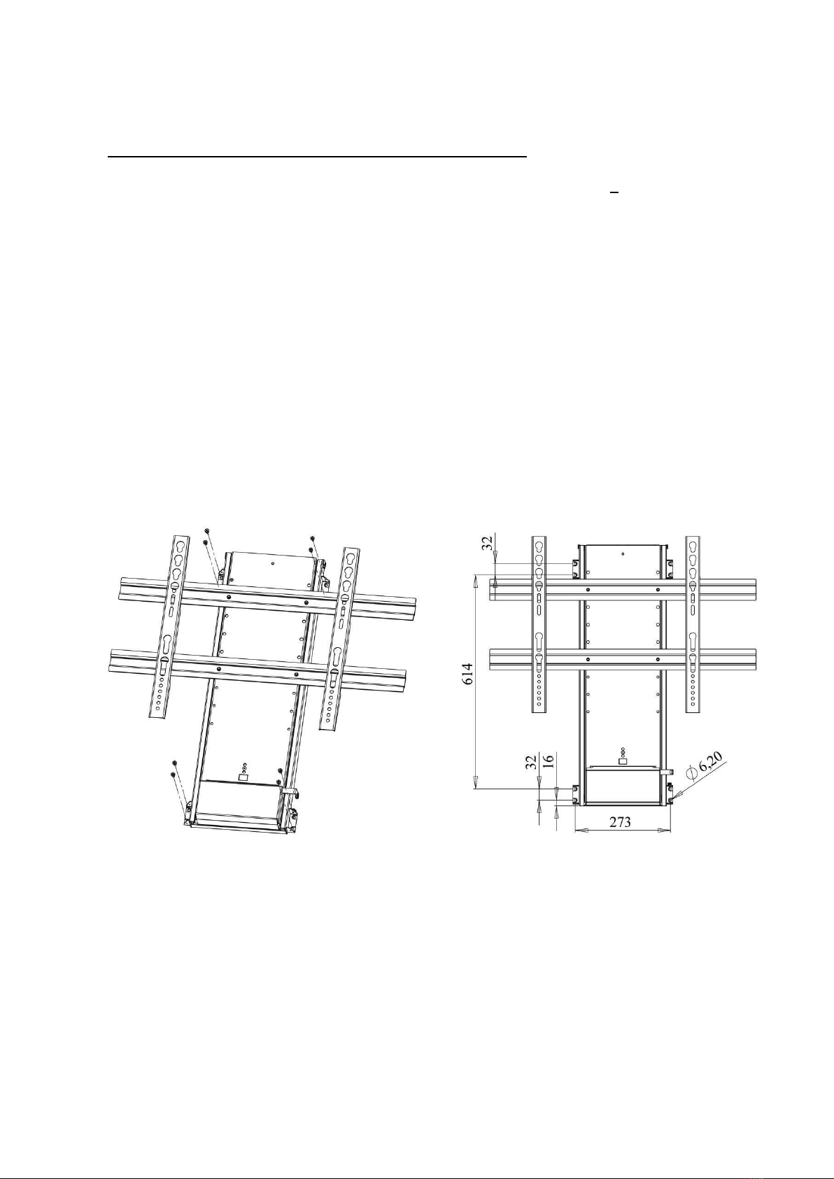
Electric TV Lift, VL-PLA-ST2-ST3
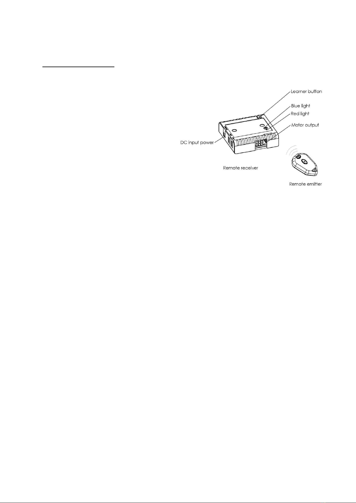
6. RF remote system.
Installation
o connect the power supply and
the motor unit to the remote re-
ceiver. 2 different plug sizes
make this connection only possi-
ble to make in the right way
o after having connected the plugs,
the blue light will be lit
o push the emitter buttons and the
motor unit will move up and down
o for stopping the motion one of the
buttons need to be pushed again
Learning
o if the remote receiver does not respond when pushing the emitter buttons, reset the
receiver. After that, code the emitter and receiver together again.
o it is possible to code up to 10 remote emitters to the remote receiver.
Coding
o push the learner button on the receiver for less than 1 sec.
o push one of the emitter buttons
o the red light will start flashing
o push one of the emitter buttons again and the red light will turn off
o the units now are coded together with a unique code
Reset
o push and hold down the learner button on the receiver for 10 sec. (will be reset when
the red light start to blink).
External rocker switch
o the external rocker switch #9 can be connected to the receiver, if a fixed operation
unit is required. This should always be fitted or accessible in case the RF handset or
battery fails.
Trouble shooting
o check the plug connections
o check whether the blue light is on
o reset the receiver and make a new coding
o always test the lift on the manual rocker switch
o see www.venset.com , click “support”
10