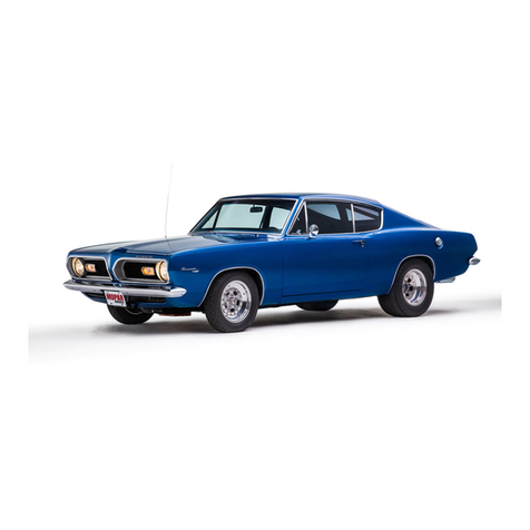
Plymouth Fury 1369 User manual


Alphabetical index
A
Air
Conditioner
Alternator
Indicator
Anti
Freeze.
Appearance Care
....
Assist
Starting
.27
3
.45
.40
Procedure...
. .13, 14
Auto Speed Control
......
_22
Auto-Temp.
.
..
.29
B Back-Up
li
ghts
B
attery
Care
Brake
System
.16
.......
43,
49
Warning
Light
....
3, 16
Brakes
Disc
..
...
,., . . . .
19
Parking .
..
......
9
Power
..
. . .19
Self
-Adj
us
ting
....
...
..
.19
Br
eak-In Inform
at
ion 9
C Capacities and
Da
ta .52
Carburetor
Air
Filter
.46
Child
Safety Features
.17
Clock.
.
.22
Convertible
Features . .
....
34
Cornering
Light
s
.....
15
Crankcase
Ventilation
System.
.
...
45
o Distrib
utor.
........
.
..
49
E Engi
ne
Performance
Evaluation . . . . . . . .
.49
Engine Specifications .54
F Fuel Filter .
..
.
...
46
Fuses . . . .
...
53
G Gaso
li
ne
....
.42, 54
Gasoli
ne
F
ille
r
Cap.
. . .
.20
H Head
Light
Beam
Selector
..
15
Head
Lights
. .
...
14
Head Restraints 6
Hea
ter
. . . . . .26
Hood
Releas
e.
. .
.20
In
strument Panel
....
4
I
nst
rument and
Gauges.
.
..
3
J
Jack
Storage
...
Jack
Storage
(Station Wagon)
K Keys .
......
.
...
39
..
33
...
5
L
License
Data
.52
Light
Bulbs
. . . . .
..
53
Lights, In
ter
ior
..
15
Locks.
...
. .
.........
17
Luggage
Compartment
..
20
M
Manifold
Heat
Control
Valve
.......
47
M
ir
rors . . . . . . . . . . 6
o
Odometer
....
. . . . . . .
..
3
Oil Pressure
Lig
ht.
. 3
Oil
Require
ments
..
47
P Parking
Brake
Warning
Light
Pa
rk
ing
Lig
hts
Perfor
mance
Eva
luat
ion
9
....
14
...
49
R Ra
dio
...
.
.............
. .23
Rear
Window
Defogger
....
26
Roa
ds
ide
Warning Flashers
16
S Safety
Be
lts 8
Safety Features
Index.
2
Seat
Adjustment
Ma
nual 5
Po
wer
. .
21
Seatback
Release 6
Service
Tips
.....••......
42
Side
Markers
........
15
Spark
Plugs
..............
49
Speedometer
..
....
3
Starting
Your
Car
........
10
Station Wagon Features
...
31
Steering
Power
.
...
....
. .
...
19
Steering
Wheel (Tilt)
..
..
.
21
Sun Visors
..
..
. .
........
18
T
Tac
home
ter
.......
.
..
22
T
ailga
te
washer/wiper
..
32
Tempe
rature Gauge 3
Thermos
tat
...
. . . . .
.46
Tire
Changing
......
38
Tire Pressures
..
35
Tire
Ro
tat
ion
.40
Tra
iler
Towing
.50
Transmission
Automatic
.....
Severe
Service
....
.11
..
42
Manual .
..........
.
...
13
Turn
Signal
Ind
ica
tors
..
.
..
.
.....
3, 15
W Wi
nd
ow
Control
..
. .21
Wind
s
hie
ld Washers
and
W
ipe
rs
...
.
..
. .
.18
'f
J".
1

2
Safety
Features
Many features for safe motoring are provided
on your new car. Some of these safety Items
can be seen
or
felt, such
as
back up lights,
padded instrument panel, mirror mount and sun
visors, and reduced glare on windshield wiper
arms.
Other safety features, such as the double hood
latch, safety rim wheels, interlocking door
locks and the energy absorbing steering wheel
and column are not
as
noticeable, but
arB
there
to serve you
if
a need should arise. Safety is
•
designed into the body structure, the chassis,
and the braking and steering systems as
an
integral part of the basic car. Each
of
these
safety developments is the result of continuing
engineeri
ng
, intensive testing, and quality
co~
trol. Improvements arB constantly being made.
Most automotive safety equipment performs its
function with little
or
no
attention or co-opera-
tion from the consumer. However, there are
some safety features which require your co-
operation to use and
ma
intain them for maxi-
mum benefit and effectiveness. The following
index lists these safety features requiring your
co-operation.
We
recommend that you give
extra attention to these sections
of
your opera-
tor's manual.
Brakes
Duat braking system .
..
.
..
. .
..
. •
•.
..
. .
16
Self-Adjusting Brakes
....
.
..
•
....
....
19
Parking Brakes . .
....
.
...
.
..
.
........
9
Head restraints
...
....
..
. •
...
. . . .
••.
..
. 6
Seat Belts . . . . . . . . . . . . . . . . . . . . . . . . . . . . . 8
Llghls
Brake System Warning Light
....
.....
3,
16
Headlight Beam Selector
..
........
..
...
15
Roadside Warning Flashers
....
.
...
.
...
16
Tum
Signals . . . .
..
.
...
...
......
.
..
3,
15
Variable Intensity Instrument Panel Light .
14
Locks
Inside Door Locks
...
.
................
17
Child-Guard Safety Door Locks . . .
...
...
17
Mirrors
Padded Inside DaylNite Mirror
.........
6
Remote Control Outside Mirror
..
.......
6
Tires . .
...
...
..
.
...
.....
......
. . . . .
...
35
Windshield
Washers-Wipers
.
....
•
•..
.
..
18

Instruments
Your instruments provide information about
what's happening
under
the hood. That's why
it's a good id
ea
f
or
you to check them
fre~
quently as you dri
ve.
A. HIGH BEAM INDICATOR:
Th
e
indicator
glows red when headlights are on high beam.
B.
ALTERNATOR
INDICATOR:
I
ndic
a
te
s
whether ballery is being charged or dis-
charged. Pointer will normally stay centered
while driving
if
battery
is
fully charged and
no
lights or accessories are in use.
C. TEMPERATURE GAUGE: I
ndicates
engine
temperature. Pointer
will
normally stay near
center while driving. If the pointer rises sud-
denUy
or
remains on "
H"
, stop car, turn off
engine and do not operate car until cause
is
located and corrected.
D.
TURN SIGNAL INDICATORS: Lights Ilash
in
unison with
exterior
lights when turn signal is
.:..-_-H
+--D
>i--G
;--F
actuated. On some models
add
itional
tum
si
g-
nal
indicators
are located on the front fenders.
E. OIL PRESSURE LIGHT: A red light i
ndi-
cates if engine oil
pr
essure
drops
below
normal. Red light should not be on except
momentarily when engine is first started
or
is
o
per
ating at idl
e.
If light stays on while
dr
iving,
do not operate ca r until cause
is
located and
corrected. Light does not indicate the amount
of
oil in the crankcase. This should be deter-
mined by periodic inspection of the dip stick.
F.
TRANSMISSION RANGE INDICATOR: Indi-
cates the
gear
range the automatic transmis- 3
sion
is
in.
G. BRAKE SYSTEM WARNING LIGHT:
Th
e
operation
of
this light
is
explained in detail on
page 16.
H. ODOMETER:
In
dicates total mileage the
car has been
dr
iven.
I.
SPEEDOMETER: Located
dir
ectly
in
front
of
you for easy visibility.
J.
FUEL GAUGE: Indicates amount
of
gaso-
line in tank when ignition key
is
turned
to
the
"on" position.

WINDSHIELD WASHER CLOCK
OR
TACHOMETER
(OPTIONAL)
WINDSHIELD
WIPER
nRUM
.ENT PANEL
AND
COURTESY LIGHTS
CONVERTIBLE
TOP,
REAR
DEFOGGER
OR
TAILGATE WINDOW (OPTIONAL) RADIO
(OPTIONAL)
REAR AIR
CONDITIONER
OR
SPEAKER FADER
(OPTIONAL)
HEATER,
AIR
CONDITIONER
OR
AUTO
-T
EMP (OPTIONAL)
ASH
AND
CIGARETIE LIGHTER GLOVE COMPARTMENT

Before Starting
Your Car
A WORD ABOUT YOUR KEYS: You will find a
small metal tag attached
to
each set
of
keys.
Stamped on each tag is an identifying
number
which
you
should
record so that
in
the
event
of loss you can or
der
duplicate
keys from your
dealer
or
locksmith.
After
recording the num-
bers, the tags should be destroyed. If you did
no
t receive tags wi
th
your
keys, ask
your
dealer
to give
you
the numbers.
CAUTION: Always remove
keys
from
the
ignilion
and
lock
all doors
when
leaving
car
unattended.
SEAT ADJUSTMENT:
The
adjust
ing lever is
located
at
the
door
side
of
the
front
seat
near
the floor. Push lever
toward
rear
to
release the
seat
so
you can slide
it
forward
or
backward
with your
body
weight
to
the most suitable
position. The seat will lock in the new position
when the lever is released. If equipped with
power seats see page
21.
SEAT ADJUSTMENT
TO RELEASE
5

6
-----;:.::=~,
,
--~-
SEATBACK RELEASE (BUCKET SEAT)
SEATBACK RELEASE HANDLE: For easy
access
to
the rear seat
on
2-door models
it
is
ne
cessary
to
relea
se
the locking
me
chanism,
that prevents the seatback from being thrust
forward under
an
impact from the
re
ar. The re-
lease handle is located at the base of the
sea
tback on all except bucket seat equipped
cars.
On
this model
it
is located on the upper
side of the seatback.
HEAD RESTRAINTS: Padded head rest
ra
ints
for the front seat reduce the risk of whiplash
injury in the event of impact from the rear. For
the driver, the head restraint is a few inches
to
the rear
of
the head for clearance
01
hats
and hairdo's. The head restraint is adjustable
vertically (except
for
bucket seats). The
upper
edqe should be at the level
of
the ears.
OUTSIDE MIRROR: To receive maximum
benefit,
adjust
the
out
side
mirror
to
ce
nt
er
on the adjacent lane
of
traffic with a slight
overlap
of
the view obtained in
th
e insi
de
mirror. A right outside mirror
is
optional.
REMOTE
-
CONTROL
OUTS
IDE
MIRROR
(OPTIONAL): Adjusted from the
driver
's seat
by a control located on the door. To adjust the
mirror
, move the control in the di
re
ction you
want the mirror
to
move.
INSI
DE
DAY
/NITE
MIRROR: Annoying head-
li
ght
glare
can
be
reduced by moving the
MIRROR CONTROL

control,
at
the lower edge
of
the
mirror
,
to
the
"
Night"
position. The
mirror
should
be
adjusted
while set in the "D
ay"
position, to
ce
nter
on the
view through
th
e rear window.
The unique mounting permits
an
adjustment
of
almost 1800 in any direction. The mirror
will pi
vo
t forward, backward or side ways from
the upper ball joint and tu
rn
or tilt from the
lower.
The
sa
fe
ty
action arm also
al
lows the mirror
to deflect out of
th
e way
if
struck.
SHOULDER
BELT
BUCKLE
7

8
SAFETY BELTS:
The
most
im
portant
safety
feature available
for
use by
yo
u and
your
family is the safety belts. Surveys have shown
that many people do not make a habit
of
wear-
ing safety belts and that many who wear them
do not wear them properly. You and
your
pas-
sengers should always f
as
ten
your
belts before
t
he
car is put in motion.
SHOULDER BELTS: The
shoulder
belt
is worn
in
addition
to
the lap belt to restrain the
upper
part of the body. A small amount
of
slack
may
be left in the shoulder belt for greater
comfort
and mobility. However,
the
less
slack
, the
greater the protection.
WARNING: The shoulder
belt
is
not
to
be used
without
a
lap
belt.
To fasten· s
hould
er belt-Unsnap fastener
ro-
cated midway in the belt stowed above door.
Pull inward on
buckle
face to release buckle
from bracket. Turn
buckle
at right angles
to
belt and pull to lengthen. Insert metal
tip
into
buckle. To tighten belt,
pull
loose end
of
belt
.
To
unf
asten s
hould
er bel
t-Pu
l
lout
on
buckle
face
to
disengage buckle. Engage
buck
le in
bracket, to the left
of
the visor. Snug bert into
storage position
by
pulling
free end
of
belt
rearward. Snap fastener in place.
LAP
BEL
TS: The lap
belt
is designed
to
be
worn
by
an occupant sitting well
back
in the
seat and sitting erect. It
should
be
worn
as
low
as possible on the abdomen and fitted snugly
across the hip bones. The belt should
be
ad-
justed as tightly
as
possible with
comfort
to
reduce any risk of sliding
under
i
t.
Sl
ouching
in
the
seat by sitting on the forward edge
or
LA
P (EXCEPT OUTER FRONT)
AND SHOULDER BELTS
·cr
lying
down
on
the
seat is not recommended,
since
there is risk
of
sliding under
the
lap
belt
and
incurring
an injury.
WARNING: Never use a
lap
belt
or
shoulder
belt
on
more
than
one person
at
a time.
To fasten
lap
be
lt
(outer front)
-Withdraw
belt
from retractor and insert metal
tip
in
buckle
.
Fit bert around abdomen
close
to
hips.
Slack
in belt
will
be automatically drawn into retrac-
tor
and
he
ld, however, make sure belt is drawn
tight
by pulling toward the retractor.
TO
AEN
US
T TO TIGHTEN

To
unfasten
lap
belt
(culer
frcnt)-D
isengage
buc
kle
by
pulling outward
on
buckle
face.
To
prevent possible damage
to
the
doo
r panel, do
not
all
ow
the
belt
to snap into the retracto
r.
The method
of
adjusting the center front and
rear lap belts and
the
use
of
th~
buckle
is
the
same as
desc
ribed for
the
sho
ulder
belt. The
front
center
buckle
shou
ld
be stored along for-
ward
edge
of
seat. To
disengage
, pull bu
ckle
face forward and lift up. To store, push
buck
le
downward onto
bracket
until a
click
is heard.
CARE OF LAP AND SHOULDER BELTS: The
nylon webbing used in
the
belts may be
cleaned with a hydrocarbon dry cleaner and
with soap or
~
dete
r
ge
n
t
in
water. Avoid
getting
dry
cleaners
or
wa
ter
solutions into
the
buckle
mechanism where they may
attack
the l
ubri-
cant
or
cause corrosion. Do
no
t
attempt
to
bleach
or
re-dye belts. Resulting
color
may
rub
oU
and
webbing
strength
may
be affected.
PARKING BRAKE:
Apply
by
firmly pressing the
foot peda
l,
located
to
t
he
left of the service
brake peda
l.
(Left of clutch pedal
if
equipped
with manual transmission).
Be sure
the
parking brake is
firm
ly set, even
on level ground, to reduce the risk
of
being
able
to
drive
with the brake applied. In addi-
tion, if equipped with
an
automatic
tra
nsmis-
sion, place the
gear
selector in the
"park"
position. As an added precaution, when park-
ing on a downhill grade, turn
the
front wheels
toward the
curb-away
from the curb on an
uphill grade.
To
release the parking
br
ake, pull
out
the
handle under the left edge
of
the instrument
panel. Always
check
to
be sure the brake is
fully released before driving.
PARKING BRAKE WARNING LIGHT: A red
light, at
the
lower l
eft
end of
the
instrument
ment panel, will light when the engine is
ru
n-
ning and the Parking Brake is applied. The l
ight
will go
out
when the
brake
is released.
BREAK-IN RECOMMENDATIONS: A long
break-in p
eriod
is n
ot
required
for
your
new
car.
Dr
ive moderately during the first 300 miles.
After
the
init
ial 50 miles, speeds up to 50 or 60
mph are desirable. While crusing,
brief
full-
throttre accelerations contribute
to
a good
break-in (within limits of state and local traf(ic
laws). Wide-open throttle acceleration in l
ow
gear can be detrimental and should be avoided
for at least 500 miles.
The oil installed
in
the engine at the factory
is a high qu
ality
lubricant, classi
fi
ed "For Ser-
vice
MS",
an
d should be retained
unt
il the first
regul
ar
oil change.
It
is
not
unusual for a new
engine to use oil during this period.
Have the oil level checked each time you stop
for fue
l.
If
oil is added, use only
oils
labeled
on the container
"For
Service
MS"
and
of
the
grade required for the outside temperature.
Nondetergent or straight mineral oils must
never be used.
9

10
Starting Your Car
CAUTION: Never
start
or
run engine in a
closed
garage
. Exhaust fumes contain
car-
bon
monoxide
gas
. Do
not
sit
in
parked
car
with
the engine running unless the
windows
are open.
AUTOMATIC TRANSMISSION: Place the se-
lector lever
in
"N"
or
"P"
position. The
eng
i
ne
will not
start
with the transmission in gear.
OFF
ACCESSORY I ON
~~
IGNITION SWITCH
MANUAL
TRANSMISSION:
Place
the gearshift
control lever in neutral and depress clutch
pedal
to
floor.
STARTER
-IGNITION
SWITCH: Controls the
electric
current
to
the starter,
distributor
, coil,
gauges, and electrically operated accessories.
NOTE: The
starter
should
not
be
operated
for
longer
than
one
minute
intervals. A
waiting
period
of
at
least
two
minutes between such
intervals
should
be observed
to
protect
the
starter
from
over-heating.
The radio, heater and other accessories con-
trolled by the switch may be used with ignition
contact disconnected by turning key
to
extreme
letl.
IGNITION SWITCH LIGHT (Standard -
Sport
Fury
& VIP): The
switch
is
lighted when either
front
door
is
opened. The light
will
remain on
for
approximately
20
seconds after
door
is
closed
to
facilitate your inserting the key.
NORMAL
STARTING-ENGINE
COLD: Depress
accelerator pedal
to
the floor and
re
lease. Turn
ignition key
to
start position and release when
the engine starts. After the engine
is
running
smoothly, tap the accelerat
or
pedal
to
reduce
the fast idle speed.
NORMAL
STARTING-ENGINE
WARM:
Hold
the
accelerator
pedal part way down while
starting.
EXTREMELY COLD WEATHER
(Below
zero):
Depress the
acce
l
erator
pedal
to
the
fl
oor
and
release; then hold pedal
part
way down while
starting. If temperature falls bel
ow
-20
°F,
start
car
only
in neutral.
NOTE: An
optional
70 amp. battery is avail-
able
from
your
dealer
for
use in extremely
cold
areas. (Standard equipment on 440
cubic
inch
engines.

UNUSUAL STARTING
CON
D I T
ION
S -
FLOODED ENGINE: Depress the accelerator
pedal fully and hold
to
the
floor
until engine
sta
rts.
TOWING A DISABLED CAR (AUTOMATIC OR
MANUAL
TRANSMISSION): Car may
be
towed
only
in
Neutral at speeds not to exceed
30
mph and distances not
to
exceed
15
mi
l
es.
If
the transmission is
not
operative,
or
the
car
is
to be towed more than 15 miles, the
propeller
shaft should be disconnected
or
the car towed
with the rear end
off
the ground.
Operating
Your Car Automatic
Transmission
COLUMN·MOUNTED GEAR SELECTOR: The
pointer on the
selector
indicates the
tr
ansmis-
sion
gear
range (selector is illuminated for
night driving), The
selector
lever is mounted on
the right side
of
the steering column. When
you are ready to
dr
i
ve,
move the selector lever
from
"P"
or
"
N"
to
the desired
dri
ve position.
Pull sel
ector
lever toward you when shifting
into reverse, second, first
or
park,
or
when
sh
ifting
out
of
park.
11

12
CONSOLE-MOUNTEO GEAR SELECTOR: The
sel
ector
on the console panel
is
illumina
te
d
for
night
driv
ing. The sele
ctor
lever may be
s
hift
ed freely from "
N"
Neutral to
"0"
Drive.
To move the lever to
or
from
"P"
park
position
or
in
to
"2"
second,
"1"
first, or
"R"
reverse
it is necessary to depress the shift lever button,
located on
top
of
the
selector
lever.
GEAR RANGES:
"P"
PARKING. Supplements parking brake by
loc
king the transmission. Engine can be started
in this range. Never use
"P
"
while
car
is
in
motion.
Apply
parking brake while in
th
is
range.
"R"
REVERSE. Use
only
when the
car
has
been stopped. Pull selec
tor
lev
er
toward you
before moving into
"R"
Reverse.
UN" NEUTRAL. Use when
car
is idling
for
long
periods. Engine can be started
in
th
is range.
"0"
DRIVE. F
or
most city and
highway
driving.
"
2"
SECOND. For driving slowly in heavy city
traffic or on mountain roads where more pre-
cise speed control is desirable. Use it also
when
climb
i
ng
long grades, and for "eng
in
e
braking"
when descending moderately steep
grades.
CAUTION: To prevent excessive
engine
speed
do
not
exceed 60 miles
per
hour
in "2" second.
" 1" FIRST. F
or
driving up very steep hills and
for
maximum engine
bra
king at low speeds
(25 miles per
hour
or
less) when going down-
hill.
CAUTION: To prevent excessive engine speed
do
not
exceed 40 miles
per
hour
in "
1"
first.
ROCKING THE CAR:
If
car
becomes stu
ck
in
snow, sand,
or
mud, it can often be moved
by
a
ro
cking motion. Move the
gear
selector
rh
ythm
ically
between
"1"
First and
"Reverse",
while
app
lying
slight
pressure to the accele-
rator.
CAUTION: Avoid racing the engine
or
spinning
the wheels. Prolonged
eflorts
to
free a
stuck
car
may result in overheating
and
transmission
failure.
PASSING ACCELERATOR: You can
get
rapid
acceleration at speeds bel
ow
60 mph in Drive,
or
25
mph in Second by pressing the
accelera
-
tor
br
iskly to the
floor
. This shifts the trans-
mission to a l
ower
gear.

HOLDING ON
AN
UPGRADE: The
car
will hold
in
any
driving
gear on a
slight
upgrade
with
light
pr
essure on the
acce
lerator, but use the
foot
brake
on
steeper
grades. Do
not
idle
en-
gine
for
long
periods
with
tr
ansmission
in
gear.
ASSIST STARTING PROCEDURES IF BAT-
TERY IS LOW (AUTOMATIC TRANSMISSION):
Assist starting can not be accomplished
by
pushing
or
lowing. Use a
booste
r
battery
or
jumper
cables from the
battery
of
another
car.
The negative
cable
on the booster battery
must be attached only
to
the negative
(-)
post, and
positive
(+)
to
positive
. Each
post
is
stamped
on
top
and
identified
on
the
battery
case. This precaution will prevent possible
damage
to
your
car's
electrical
system.
Manual
Transmission
Go
through
each
gear
in
numerical
order-do
not skip a gear. Fuel can be saved by shifting
from 2nd
to
3r
d
gear
as soon as practical.
Never s
hift
into Reverse
or
L
ow
when
car
is
moving.
SHIFTING GEARS: When shifting gears (1)
Depress
clutch
pedal to floor.
(2)
Move shift
lever to desired position.
(3)
Release
clutch
pedal and press d
ow
n on
acce
l
erator
p
edal
at
the same time. Do
not
drive
with
your
foot on
the
clutch
pedal as this will cause abnormal
clutch wear.
NOTE:
Make
sure,
when
shifting
into
low
or
reverse,
that
the
clutch
pedal
is
fully
de-
pressed,
otherwise
the shift will be blocked.
This
minimizes
gear
clashing.
DOWN SHIFTING: Shifting from "
High"
gear
to
"Second"
gear
is recommended to preserve
brakes when
driving
down steep hills. In
addi-
tion, d
own
shifting
at
the r
ight
time
provides
better
acceleration
when you
desire
to
resume
speed. F
or
acceleration
in
itiating at
speeds
less
than 20 MPH,
second
gear
is recommended.
DOWN SHIFT SPEEDS
3-Speed
Transmission
Th
ird
to
Second 40 to 10
Second
to
First 0
COLUMN MOUNTED
3 SPEED
13

14
ASSIST STARTING IF BATTERY IS LOW
(
MANUAL
TRANSMISSION): With a manual
transmission you can
get
an assist start from
borrowed battery
power
(as
described
on
.previous page under "Assist Starting Proce-
dures")
or
by pushing. When pushing make
sure the bumpers on both cars align properly.
Turn the ignition key to
"On",
shift
to
"High"
gear
then depress the
clutch
pedal and hold
it there. When a speed of about 10 mph is
reached, depress the
acce
l
erator
pedal and
slowly release the
clutch
pedal and engine
should start.
Do
not
get an assist start by having the
car
towed as it
could
collide
with the
tow
vehicle
when the
~ng
i
ne
starts.
HEADLIGHTS
AN
D PARKING LIG
HT
S: The
parking lights, taillights, license plate light.
and instrument panel lights all turn on when
the
headlight
switch is depressed to the first
position. Headlights turn on when switch is
fully depressed.
LIGHTS ON REMINDER (Option
al)
: If the
headlights
or
parking lights are left on inad-
vertently
after
the ignition is turned off. a
buzzer will sound when
either
front
door
is
opened.
Have headlight aim corrected whenever it
appears necessary,
especially
after any dam-
age to the front end
of
the car.
All Chrysl
er
Corp. cars have headli
ght
adjust-
ment screws that are accessible without re-
moving bezels.
2ND POSITION
HEAD LIGHTS
~
1
ST
POSITION
PARKING LIGHTS
...J
..
..
~
"
"
Ii
".
0
I
~
.....
LIGHTS
Give
as
much attention to cleanliness
of
the
headlights as you give to the windshield, rec-
ognizing
that
their
low forward position sub-
jects
them to even greater amounts
of
dirt
from the road.
PANEL LIGHTING: The brightness can be reg-
ulated by turning the thumbwheeJ up
or
down.
To assure maximum
night-
time driving visi-
bility, it is recommended that the panel li
ght-
ing be
adjusted
to the minimum brightness
necessary to see the speedometer and other
essential instruments.
OFF

HEADLIGHT BEAM SELECTOR: Push the f
oot
-
operated
button on t
he
fl
oor
to alternate
the
headlights between
"high"
an
d
"low"
beam.
A small red
light
on the inst
rument
cl
uster
indicates
when
the
"h
i
gh"
beam is on. Dim-
ming the lights
fo
r
an
oncoming car
is
a cou
r-
tesy which benefits
both
drivers. On curved
sect
ions
of
all
highways
,
dim
the lights if your
beams are likely to intercept the oncoming
car
on
the
cu
rYe
ahead.
CORNERING LIGHTS
(if
so
equipped):
With
t
he
headli
ghts
on and turn
signa
l
ope
rati
ng
,
the
corresponding
cornering
l
ight
located on
t
he
si
de of each front fender, provides addi-
tional
illumi
nation.
SIDE MARKERS: Your
car
is equipped with
f
our
side
markers
that
give it a more visible
pr
of
il
e.
The markers are mounted in each front
fen
der
and each 'qua
rt
er panel.
INTERIOR LIGHTS: The
number
of inter
io
r
l
ights
and the
ir
location varies
accor
ding to
body
styl
e.
However, all map, courtesy, and
dome lights are turned on by
opening
a
door
or turni
ng
t
he
thumbwheel all the way
up
.
NOTE: The
instrument
panel
lights
,
the
i
nterior
dome
lights,
and
the
exterior
stop
and
tail-
lights
are
all
protected
by
the
same fuse.
If
the
fuse
fails
these
lights
will
not
op
e
rate
.
If
at
any ti
me
panel
or
dome
light
is
not
operat-
ing
make
a
check
of
the
stop
and
taillights
to
be sure
that
they
are
operational
and
that
a
fuse
has
not
failed
.
DOME-READING LIGHT
(Optional
on
most
models):
This combination
light
serves ei
ther
as a
dome
or
reading light. T
he
dome
light
is turned on
by
opening a
door
or
turning the
READING-
DOME LIGHT
instrume
nt
panel light
thumbwhee
l all the way
up. To operate as a reading li
ght
move t
he
toggle
switch
toward
the dome
light
lens.
TURN SI
GNAL
LIGHTS: Move
tum
signal
lever
UP
to signal right turn or DOWN to Signal left
turn. With
the
lever in
either
position, parki
ng
l
ights
and
tailligh
ts flash
to
alert
other
drivers
the direction you are
about
to turn. Lever
au
t
o-
matically cancels signal
after
turn, but may
require manual
cancell
ing after a
wide
, sweep-
ing turn.
T
ur
n sign
als
should
also be used to al
ert
othe
r
motorists
when changing lanes
or
leaving the
curb. Signal shou
ld
be applied
at
least three
seconds before begi
nn
ing the maneuver.
NOTE: On vehi
cles
e
quipp
ed with Tilt-stee
ring
wheel the
turn
signals
incorpora
te a
lan
e
changing
feature.
To
oper
ate,
mov
e lever to
a pos
it
ion mi
dway
between t
he
normal
turn
and
c
ancelled
position.
Hold lever unt
il
lane
ch
ange
is
comple
ted, then release lever.
II
will
automatically
return
to
the ca
nc
e
ll
ed
pos
i
tion
.
NOTE: If t
he
lIasher operates weakly
or
fails
to
flash, the
possibl
e cause is a
burned
out
bulb
. Immediate
bulb
replace
ment
to
res
tore
the system
is
essen
ti
al
to
safe
motoring
.
15

16
The heavy duty flash
er
used in the trail
er
t
ow-
ing package
is
less sensitive to el
ectrica
l load
variations a
nd
does
not
pr
oduce
the usual
in
di
cat
ion
of
ex
ter
ior
bulb
failure. Theref
ore
,
an
occas
ional visual check around the car
is recommended.
BRAKE SYSTEM WARNING LIGHT: The dual
br
aking system provides an emergency
br
ak-
ing capab
ilit
y in the event
of
a
fa
ilure to a
portion
of
the
hydraulic
system. Failure of
eith
er
half of the dual system is i
ndica
ted by
the brake warning
li
ght
in the instrument cluster
which
will
glow
each time t
he
servi
ce
br
ake
pedal is depressed.
WARNING.:
If
brake
failure
is
indicated,
im
-
mediate
repair
service
is
necessary.
Continued
operation
of
the
car
in
this
condition
is
dan-
gerous.
T
he
light bulb should be
checked
frequently
by turning the ignition key to the
"on"
p
osi-
tion with t
he
parking
brake engaged. Do
not
move
th
e car
unt
il t
he
brake is released and
t
he
light is off.
ROADSIDE WARNING FLASHER: This warn-
i
ng
system should be used
during~e
m
ergency
stops. Place flasher
switch
in
"ON"
position
and the fr
ont
directional si
gna
ls and taillights
fl
ash interm
ittent
ly. Be
su
re t
he
turn signal
l
ever
is
in
t
he
neut
ral position. This is a warn-
ing system only and should not be used when
t
he
car is in
mo
tion. Pressure on t
he
brake
pedal will ove
rrid
e the f
lasher
an
d result in
constant lights. When
it
is necessary
to
leave
the
car
to go
for
service
or
help
, t
he
flasher
ROADSIDE WARNING
FLASHER
system will conti
nue
to
operate
even though
the ignition is of
f.
BACK
UP LIGHTS: These lights turn on
auto-
matically
when
the
ignition is on and the
transmission is in reverse.
OUTSIDE DOOR LOCKS: Both Ir
ont
doors, if
locked before closing, will automatically
un
-
l
ock
when shut. This feature prevents l
ock
i
ng
yourself out of the
car
with the keys inside.
TO THAW FROZEN LOCK
I
\
HEAT KEY
AND INSERT

Front doors must be locked from
outs
ide using
the ignition key.
Always l
ock
all doors when leaving the
car
unattended.
Never invite theft by leaving packages exposed
inside the car. Put them
in
the trunk
or
take
them with you.
Always try
to
park
your
car
in
a well lighted
area and
lock
it, even in
your
own driveway.
\TO LOCK
"TO
UNLOCK
OUTSIDE DOOR LOCKS
INSIDE DOOR LOCKS: Pressing the inside
butto
ns down to
lock
all d
oors
is
an
exce
llent
safety
pr
ecaution. When locked from the in-
side, the
door
cannot be opened by
an
intruder
nor
is
it
likely
to
open as the result
of
an
impact
on the outside release button. All
door
locks,
except
the drivers, are designed so that
two separate operations are required to open
the doors
once
they are locked.
Fir
st, the push
button must be raised and then the inside do
or
handle can be
pu
lle
d.
This reduces the passi-
LOCK_
INSIDE DOOR LOCKS
b
ility
of
the
doors
being opened
accidentally
while the
car
is
in
motion. Small children riding
in
the rear seat
of
a fou
r-
door
sedan can be
discouraged from
going
through the process
by the addition
of
a p
air
of
"Ch
ild-Guard Door
L
ocks".
CHILD-GUARD DOOR LOCKS (DEALER IN-
STALLED): The
cost
of
the unit from your
de
al
er
is nominal for the protection obtained.
Your
adult
passengers should be advised
of
the operation
of
this device so that they will
not be confused when trying to leave the car.
CHILD GUARD
DOOR
LOCK
TO LOCK TO UNLOCK
17

18
ELECTRIC INSIDE DOOR LOCKS (OPTIONAL):
All doors can be locked and unlocked auto-
matically from inside by a switch
on
either
of
the
front
doors. Move switch
down
to l
ock
,
up
to unlock. To lock doors from outside the car,
place the switch in the locked position, to l
ock
other
doo
rs,
close
the
door
and use
door
key
in
the
normal manner.
INSIDE DOOR HANDLE: T
he
doors are opened
from the
in
side by a handle located at the
forward end
of
the armrest. Pull towards
center
of
car
to open.
SUN VISORS: Sun
glare
through
th
e win
d-
shield
or
front
wi
ndow can be reduced by
tilting
or
swinging the padded visor down-
ward
or
outward. Pull
out
of
retaining
bracket
betore m
oving
to
side
.
-:]i
PULL
IN
TO
OPEN
INSIDE DOOR HANDLE
WINDSHIELD WIPERS: To
ope
rate win
dsh
ield
wiper, push lever up to desired sp
ee
d.
Fu
lly
down is
off
position. A
thr
ee
-speed wiper is
optional.
NOTE:
If
the
wiper
blades need
to
be
freed
of
ice and snow before operating
wiper
, opening
the hood
will
provide
greater access.
WINDSHIELD WASHERS: Push windshield
washer button to s
pr
ay fluid
on
windshield.
Button is next to
wiper
switch. F
lu
id will spray
as long as button is held
in
, enabling you to
use just the amount needed
for
a good clean-
ing job.
-PUSH

During
cold
weather, two precautions are recw
ommended: use a windshield washer solution
containing an antiwfreeze
especially
designed
f
or
this use and, if the
car
interior
is cold,
oper-
ate the
defroster
for
a few minutes to reduce
the possibility
of
smearing
or
freezing the fluid
on the cold windshield.
Chrysler
All Weather
Windshield Washer Solution used with water
as
directed
on the container aids cleaning
action, reduces freezing point
to
avoid line
clogging
and is
not
harmful to paint
or
trim.
The
container
in
the engine
compartment
should be checked for fluid level
at
regular
intervals.
VENT WINDOW CONTROL: Control handles
are located below the vent windows on each
front
door
panel. To open, turn toward front
of
car
, to close reverse this procedure. Vent
windows should be opened to about a
45
0
angle
for
mo
st
efficient ventilation.
Some
two
door
hardtops equipped with
air
conditioning have single-pane, fullwsize vent-
less
windows
in
their
front doors.
SELF-ADJUSTING BRAKES: This feature
eliminates manual adjustment
of
your
brakes.
A few brake pedal
applications
during
"re-
verse"
driving
will maintain
your
brakes
at
the
specified
adjustment.
Adjustment
will
cont
inue
unt
il t
he
brake
lining is worn away.
To avoid
poor
braking, brake pull, or damage
to brake drums the
brake
linings should be
in
spected every 12,000 miles.
NOTE:
Trailer
towing
and heavy
duty
brakes
are
not
self
adjusting.
DISC BRAKES (OPTIONAL, FRONT WHEELS):
The disc brake provides extra reserve in
stop
w
ping ability and anti-fade characteristics un-
der
a variety
of
speed, weather, and terrain
conditions. These brakes do
not
require any
adjustments.
CAUTION:
It
is
important
that
you
do
not
drive the
car
with
your
foot
resting
or
riding
on the
brake
pedal, when
braking
is
not
rew
quired. This
practice
can result
in
abnormally
high
brake
temperatures, excessive lining
wear
and
possible damage
to
the brakes.
POWER BRAKES (OPTIONAL): The reduced
braking
effort provided by power brakes alw
lows the
driver
to bring the
car
to
a fast,
smooth stop. Power brakes can be installed
by
your dealer.
WINTER BRAKING: When traction
is
reduced
due to snow covered
or
icy
pavements, the
wheels may
lock
and the
car
cannot be
readily
brought
to
a stop
by
conventional
braking techniques.
If
a skid
occurs,
remove your foot from the
brake
pedal and
stop
the
car
by
"pump
i
ng"
the brake pedal with short rapid
"jabs".
With
each
jab
the
brake
must be fully
applied
and
fully released
for
greatest effect.
POWER STEERING (OPTIONAL):
Power
steer-
Ing offers positive steering action and easier
veh
ic
le handling
which
incr
eases the driver's
effective control.
19
Other Plymouth Automobile manuals

Plymouth
Plymouth Plaza 1957 User manual

Plymouth
Plymouth Gran Fury 1980 User manual

Plymouth
Plymouth Valiant 200 1969 User manual

Plymouth
Plymouth Gran Fury1976 User manual

Plymouth
Plymouth Plaza 1955 User manual

Plymouth
Plymouth Cranbrook User manual

Plymouth
Plymouth SAVOY 1961 Operating manual

Plymouth
Plymouth Valiant 1968 User manual

Plymouth
Plymouth Pl4S User manual

Plymouth
Plymouth Valiant V-100 1965 User manual