Plymouth SAVOY 1961 Operating manual


SERVICE MANUALSERVICE MANUAL
SUPPLEMENTSUPPLEMENT
77
awcu~aawcu~a
This Plymouth Service Manual Supplement has been preparedThis Plymouth Service Manual Supplement has been prepared
to cover only changes affecting the servicing procedures of theto cover only changes affecting the servicing procedures of the
1961 model cars.1961 model cars.
For complete servicing of 1961 Plymouth cars, use the 1960For complete servicing of 1961 Plymouth cars, use the 1960
Plymouth Service Manual in conjunction with this supplement.Plymouth Service Manual in conjunction with this supplement.
For your convenience, the group numbering in this supple-For your convenience, the group numbering in this supple-
ment is arranged to correspond to that used in the 1960 Plymouthment is arranged to correspond to that used in the 1960 Plymouth
Service Manual. Each group contains the latest new informa-Service Manual. Each group contains the latest new informa-
tion concerning the servicing of the 1961 Plymouth cartion concerning the servicing of the 1961 Plymouth car
compc-compc-
nents, without repeating recommended procedures for previousnents, without repeating recommended procedures for previous
models. Specifications, special tools, torque reference andmodels. Specifications, special tools, torque reference and
service diagnosis, when they apply, appear in the individualservice diagnosis, when they apply, appear in the individual
group.group.
The procedures and specifications contained in this manualThe procedures and specifications contained in this manual
were in effect at the time the manual was approved for printing.were in effect at the time the manual was approved for printing.
Chrysler Corporation reserves the right to change proceduresChrysler Corporation reserves the right to change procedures
and specifications without notice and without incurring obliga-and specifications without notice and without incurring obliga-
tion.tion.
CHRYSLER CORPORATIONCHRYSLER CORPORATION
To obtain extra copies of this manual,To obtain extra copies of this manual,
Order by Number 81-571-0038Order by Number 81-571-0038
C H R Y S L E R C O R P O R A T I O NC H R Y S L E R C O R P O R A T I O N
PLYMOUTHPLYMOUTH ll DE SOT0DE SOT0 ll VALIANT DIVISIONVALIANT DIVISION
SSERERVIVICCE DEPE DEPAARTRTMENTMENT
DETDETRROOIT IT 31, MIC31, MICHIGHIGAANN
81.571403881.5714038
15M SD15M SD
8.8.
TO-840 TO-840
LITHO LITHO
IN U.S.A.IN U.S.A.
GROUP INDEXGROUP INDEX
ZOUPZOUP
TTIITTLLEE PPAAGGEE
00
lu bric a t io n - M a i n t e na nce lu bric a t io n - M a i n t e na nce 33
AA
ccessoriesccessories
77
22
Front Suspension Front Suspension
33
A x l e - R e a r A x l e - R e a r 1133
44
B r a k e s B r a k e s 1166
66
Clutch Clu tc h 1199
77 Cooling SystemCooling System 22 00
88
Electrical-InstrumentsElectrical-Instruments 22 55
99
Eng i n e - E n gin e O i lin gEng i n e - E n gin e O i lin g
66 22
1111
E x h a u s t E x h a u s t 8811
1313
Fr a m eF rame 88 22
1414
Fuel SystemFuel System 88 22
1616 PropellerPropeller
Shaft-Shaft-
11 0202
Universal JointsUniversal Joints
1717
Springs-Shock AbsorbersSprings-Shock Absorbers 103103
1919
Stee r i n g Ge ars S t e e rin g Gea r s
2121
Transmissions Transmissions 113113
Whee l s - B e a rings - T i r e sWhee l s - B e a rings - T i r e s 142142
Bod y - S h ee t Me t a lBo d y-S he et Me t a l 142142
44
Air Con ditio ning Air Con ditio ning

II

LUBRICATION-MAINTENANCELUBRICATION-MAINTENANCE 33
1961 MODELS1961 MODELS
SAVOY (6SAVOY (6 Cyl.)Cyl.) RP1-LRP1-L(8 Cyl.)(8 Cyl.) RP2-LRP2-L
BELVEDERBELVEDERE (6 E (6 Cyl.) RCyl.) RPP11--M (8 M (8 Cyl.) RP2Cyl.) RP2-M-M
FURY (6 Cyl.)FURY (6 Cyl.) RP1-HRP1-H(8 Cyl.)(8 Cyl.) RP2-HRP2-H
PLYMOUTH VEHICLE NUMBERSPLYMOUTH VEHICLE NUMBERS
All vehicle numbers contain ten digits. The vehicleAll vehicle numbers contain ten digits. The vehicle
number is a code which tells the make of car (1stnumber is a code which tells the make of car (1st
digit), model of car (2nd digit), year built (3rd digit),digit), model of car (2nd digit), year built (3rd digit),
assembly plant (4th digit) and vehicle serial numberassembly plant (4th digit) and vehicle serial number
(last six digits).(last six digits).
VEVEHIHICLCL E E NUNUMBMBER ER LOLOCACATITI ONON The vehicleThe vehicle
number (serial number) is located on a plate whichnumber (serial number) is located on a plate which
it attached to the left front door hinge pillar post.it attached to the left front door hinge pillar post.
aa ENGINE NUMBER LOCATIONENGINE NUMBER LOCATION On 6 cylinderOn 6 cylinder
engines, the engine model, cubic inch displacement andengines, the engine model, cubic inch displacement and
manufacturing date are all stamped on top of a boss,manufacturing date are all stamped on top of a boss,
located on the right side of block opposite numberlocated on the right side of block opposite number
one cylinder next to the cylinder head. See illustration.one cylinder next to the cylinder head. See illustration.
On 318 cubic inch V-8 engines, the number is locatedOn 318 cubic inch V-8 engines, the number is located
on the left front face of the cylinder block in positionon the left front face of the cylinder block in position
“B” as shown. On 361 cubic inch V-8 engines, the“B” as shown. On 361 cubic inch V-8 engines, the
//
number is located on the right side of cylinder blocknumber is located on the right side of cylinder block
next to the water pump housing in position “A’.next to the water pump housing in position “A’.
BODY NUMBER LOCATIONBODY NUMBER LOCATION The body number isThe body number is
stamped on a plate attached to the engine side ofstamped on a plate attached to the engine side of
dash or front of radiator yoke.dash or front of radiator yoke.
1st Digit1st Digit 2nd Digit2nd Digit 33rrd d DDiiggiitt 44tth h DDiiggiitt
2-Plymouth2-Plymouth (6(6 Cyl.)Cyl.) 1 . 1 . L o wL o w 66. . SSuubbuurrbbaann--MMeeddiiuumm 11996611 11.. DetroitDetroit
3-Pl3-P lymouymouthth ((88 CCyyll..)) 22.. MMeeddiiuumm 77. . SSuubbuurrbbaann--HHiigghh 55.. LLoos s AAnnggeelleess
33.. HHiigghh 88. . TTaaxxii 6.6. N e w a r k N e w a r k
55.. S uSububurbarban-Ln-Lo wo w 99. . SSppeecciiaall 77.. VVaalllleey y PPaarrkk
GROUP 0GROUP 0
LUBRICATION AND MAINTENANCELUBRICATION AND MAINTENANCE
Listed are the new Lubrication and MaintenanceListed are the new Lubrication and Maintenance pro-pro- NOTE: The rubber bushings used on theseNOTE: The rubber bushings used on these
cedures for the 1961 Plymouth cars. These newcedures for the 1961 Plymouth cars. These new cars are designed to grip the contactingcars are designed to grip the contacting
procedures also apply to the 1960 models whereprocedures also apply to the 1960 models where metal parts firmly and operate as a flexiblemetal parts firmly and operate as a flexible
applicable. All other Lubrication and Maintenanceapplicable. All other Lubrication and Maintenance medium between these parts. The use of anymedium between these parts. The use of any
remain the same as outlined in the 1960 Plymouthremain the same as outlined in the 1960 Plymouth lubricant will destroy the necessary frictionlubricant will destroy the necessary friction
Service Manual.Service Manual. and cause premature failure of the rubber.and cause premature failure of the rubber.

44 LUBRICATION-MAINTENANCELUBRICATION-MAINTENANCE
LUBRICATION AND MAINTENANCELUBRICATION AND MAINTENANCE
CAPACITIESCAPACITIES
MMOODDEELL 6 6 CCyyll.. 8 8 CCyyll.. Golden CommandoGolden Commando
Crankcase (a) . . . . . . . . . .Crankcase (a) . . . . . . . . . .
Cooling (b) . . . . . . . . . . .Cooling (b) . . . . . . . . . . .
Fuel Tank (c). . . . . . . . . . . . . . .Fuel Tank (c). . . . . . . . . . . . . . .
RR ee aa r r AA xx ll ee . . .. . . . . . . . . . . . . . . . . . . . . ..
Tire Pressure (d)Tire Pressure (d)
4 4 qqttss.. 5 5 qqttss.. 5 5 qqttss..
113 3 qqttss.. 220 0 qqttss.. 116 6 qqttss..
220 0 ggaall.. 220 0 ggaall.. 20 gal.20 gal.
31/431/4
pts. pts.
31/z 31/z
pts. pts.
31/z 31/z
pts. pts.
FF rr oo nn tt .. .. .. .. .. .. .. .. .. .. .. .. .. .. .. .. .. .. .. .. .. .. .. .. .. .. .. .. .. .. .. .. .. .. .. .. .. 2222 2244 2244
Rear. . . . . . . . . . . .Rear. . . . . . . . . . . . 2222 2222
((224 4 SSuubbuurrbbaann)) ((2244
SuErban)SuErban)
TransmissionsTransmissions
Torqueflite 8. . . .Torqueflite 8. . . .
Torqueflite 6. . . . . . . .Torqueflite 6. . . . . . . .
PowerFlite PowerFlite . . . . . . .. . . . . . .
M a n u a l 3 S p e e d ( S t a n d a r d V - 8 E n g . )M a n u a l 3 S p e e d ( S t a n d a r d V - 8 E n g . )
Manual 3 Speed (Golden Commando Eng.)Manual 3 Speed (Golden Commando Eng.)
Manual 3 Speed (6 Cylinder) . . . . . . .Manual 3 Speed (6 Cylinder) . . . . . . .
--
14 pts.14 pts.
--
5 pts.5 pts.
18 pts.18 pts.
20 pts.20 pts.
5 pts.5 pts.
21 pts.21 pts.
41/441/4
pts. pts.
(a) Add 1 qt. if filter is changed(a) Add 1 qt. if filter is changed (c) Suburbans 22 gallons(c) Suburbans 22 gallons
(b) Add 1 qt. for heater(b) Add 1 qt. for heater (d) 28 psi for fully loaded Suburban(d) 28 psi for fully loaded Suburban
Key To Lubrication and Maintenance ChartKey To Lubrication and Maintenance Chart
KeyKey
AA-Automatic Transmission Fluid Type “A”AA-Automatic Transmission Fluid Type “A”
Suffix “A’Suffix “A’
AF-Anti-freezeAF-Anti-freeze
AP-Air PressureAP-Air Pressure
C-Check Condition ofC-Check Condition of
CAC-Carburetor Air CleanerCAC-Carburetor Air Cleaner
CL-Chassis LubricantCL-Chassis Lubricant
DCL-Distributor Cam Lubricant-Part No. 1473595DCL-Distributor Cam Lubricant-Part No. 1473595
DPO-Dripless Penetrating Oil-Part No. 830669DPO-Dripless Penetrating Oil-Part No. 830669
EO-Engine OilEO-Engine Oil
EOF-Engine Oil FilterEOF-Engine Oil Filter
GL-4-For API Service GL-4 as defined by MIL-L-2105BGL-4-For API Service GL-4 as defined by MIL-L-2105B
HTF-High Temperature Heavy Duty Brake FluidHTF-High Temperature Heavy Duty Brake Fluid
Conforming to Conforming to SAE SAE 7ORl 7ORl and 70R3and 70R3
MCL-Speedometer Cable Lubricant Part No. 1243632MCL-Speedometer Cable Lubricant Part No. 1243632
ML-Lubriplate Part No. 1064768ML-Lubriplate Part No. 1064768
MP-Multi-Purpose Gear LubricantMP-Multi-Purpose Gear Lubricant
MSO-MSO- Speedometer Lubricating Oil Part No. 1265805 Speedometer Lubricating Oil Part No. 1265805
PSF-Power Steering Fluid Part No. 2084329PSF-Power Steering Fluid Part No. 2084329
RF-Reverse FlushRF-Reverse Flush
RR-Rust ResistorRR-Rust Resistor
S-Manifold Heat Control Valve Solvent Part No. 1879318S-Manifold Heat Control Valve Solvent Part No. 1879318
SC-Safety Check-Brakes, Steering, Exhaust, Wipers,SC-Safety Check-Brakes, Steering, Exhaust, Wipers,
Mirrors, Tires, Horn, Lights, GlassMirrors, Tires, Horn, Lights, Glass
KeyKey
SGL Sure-Grip Lubricant Part No. 1879414SGL Sure-Grip Lubricant Part No. 1879414
SSL-Stainless Stick Lubricant Part No. 1064769SSL-Stainless Stick Lubricant Part No. 1064769
UJl-UniversalUJl-Universal Joint Lubricant No. 1 Joint Lubricant No. 1
UJ2-UniversalUJ2-Universal Joint Lubricant No. 2 Joint Lubricant No. 2
UBM-Short Fiber Wheel Bearing Grease, MediumUBM-Short Fiber Wheel Bearing Grease, Medium
At THE FIRST 1,000 MILE SERVICEAt THE FIRST 1,000 MILE SERVICE
AND THEREAFTER ATAND THEREAFTER AT
2,000 MILE OR 2 MONTH INTERVALS2,000 MILE OR 2 MONTH INTERVALS
KeyKey
CL-Upper Ball Joints (2)CL-Upper Ball Joints (2)
CL-CL- Lower Ball Joints (2) Lower Ball Joints (2)
CL-Tie Rod Ball Ends (4)CL-Tie Rod Ball Ends (4)
CL-Clutch Torque Shaft (1)CL-Clutch Torque Shaft (1)
CL-Gearshift Tube and Lower Support Assembly (1)CL-Gearshift Tube and Lower Support Assembly (1)
MP or GL-4-Manual Steering Gear-Check LevelMP or GL-4-Manual Steering Gear-Check Level
PSF-Power Steering-Check LevelPSF-Power Steering-Check Level
EO-Parking Brake Linkage (Man. Trans.)EO-Parking Brake Linkage (Man. Trans.)
MP or GL-4-Rear Axle-Check LevelMP or GL-4-Rear Axle-Check Level
SGL-Rear Axle-Sure Grip-Check LevelSGL-Rear Axle-Sure Grip-Check Level
AA Automatic Transmission-Check LevelAA Automatic Transmission-Check Level
MP or GL-4-Manual Transmission-Check LevelMP or GL-4-Manual Transmission-Check Level
ML-Foot Operated Parking BrakeML-Foot Operated Parking Brake
EO-Distributor-Oil CupEO-Distributor-Oil Cup
DPO-Door Hinges and other hard to lubricate placesDPO-Door Hinges and other hard to lubricate places

LLUUBBRRICIC ATATIOION-N-MAINTMAINTENANCENANC EE 55
KeyKey
SSL-Door Lock Striker Plates, Dove Tail SurfacesSSL-Door Lock Striker Plates, Dove Tail Surfaces
S-Manifold Heat Control ValvesS-Manifold Heat Control Valves
ML-Door Check Arms, Hood Hinges, Hood LockML-Door Check Arms, Hood Hinges, Hood Lock
DPO-Door Lock AssemblyDPO-Door Lock Assembly
ML-Door Lock CylindersML-Door Lock Cylinders
ML-Deck Lid LockML-Deck Lid Lock
ML-License Plate Mounting Panel Springs and PinML-License Plate Mounting Panel Springs and Pin
DPO-Tail Gate HingesDPO-Tail Gate Hinges
ML-Tail Gate LocksML-Tail Gate Locks
SSL-Tail Gate Striker Plates, Dove Tail SurfacesSSL-Tail Gate Striker Plates, Dove Tail Surfaces
ML-Fuel Tank Access Cover Hinge and PinML-Fuel Tank Access Cover Hinge and Pin
EO-Engine Oil ChangeEO-Engine Oil Change
SC-lo-Point Safety CheckSC-lo-Point Safety Check
EO-Engine Ventilation Air CleanersEO-Engine Ventilation Air Cleaners
C-Tires-Air-Wear-Foreign MatterC-Tires-Air-Wear-Foreign Matter
C-Brake Lines and HosesC-Brake Lines and Hoses
HTF-Master Cylinder Check LevelHTF-Master Cylinder Check Level
EOF-Engine Oil Filter Change (First change atEOF-Engine Oil Filter Change (First change at
3000 miles)3000 miles)
AT 4,000 MILE INTERVALSAT 4,000 MILE INTERVALS
EOF-Engine Oil Filter ChangeEOF-Engine Oil Filter Change
AT 6,000 MILE INTERVALSAT 6,000 MILE INTERVALS
Rotate TiresRotate Tires
AT 10,000 MILE OR 12 MONTHAT 10,000 MILE OR 12 MONTH
INTERNALSINTERNALS
-Closed Crankcase Ventilation System---Closed Crankcase Ventilation System--
Disassemble and cleanDisassemble and clean
WBM-Front Wheel Bearings-Check Brake Lining,WBM-Front Wheel Bearings-Check Brake Lining,
Wheel Cylinders, HosesWheel Cylinders, Hoses
MSO-Speedometer-with tube and wick or oilerMSO-Speedometer-with tube and wick or oiler
MCL-SpeedometMCL-Speedometer er CableCable
EO-Distributor WickEO-Distributor Wick
DCL--Distributor CamDCL--Distributor Cam
ML-Gear Shift LeverML-Gear Shift Lever
AA-Automatic Transmission Maintenance andAA-Automatic Transmission Maintenance and
Fluid ChangeFluid Change
AT 15,000 MILE INTERVALSAT 15,000 MILE INTERVALS
CAC-Install New Carburetor Air Cleaner ElementCAC-Install New Carburetor Air Cleaner Element
AT 20,000 MILE OR TWO YEARAT 20,000 MILE OR TWO YEAR
INTERNALSINTERNALS
MP or GL-4-Drain and Refill Manual TransmissionMP or GL-4-Drain and Refill Manual Transmission
KeyKey
MP orMP or GL-4-DrainGL-4-Drain and Refill Rear Axle and Refill Rear Axle
(SGL for Sure-Grip)(SGL for Sure-Grip)
UJlUJl Ball and Trunnion Universal Joint-Disassemble, Ball and Trunnion Universal Joint-Disassemble,
Clean, Inspect, RepackClean, Inspect, Repack
UJ2-CrossUJ2-Cross and Roller Universal Joint-Disassemble, and Roller Universal Joint-Disassemble,
Clean, Inspect, RepackClean, Inspect, Repack
MP-Front Door Intrusion Guard PivotsMP-Front Door Intrusion Guard Pivots
1. ENG1. ENGINE VINE VENTENTILATILATINING G SYSSYSTTEMSEMS
All engines have an air cleaner on the cylinder headAll engines have an air cleaner on the cylinder head
cover to clean the incoming air. As optional equipment,cover to clean the incoming air. As optional equipment,
all engines (except in California) can be equippedall engines (except in California) can be equipped
with an air cleaner on the road-draft (outlet) tube.with an air cleaner on the road-draft (outlet) tube.
These air cleaners should be washed in kerosene andThese air cleaners should be washed in kerosene and
reoiled with SAE 30 engine oil at each 2,000 mile-2reoiled with SAE 30 engine oil at each 2,000 mile-2
month interval. In smog or dusty areas the air cleanersmonth interval. In smog or dusty areas the air cleaners
may need attention as often as 500 miles, and inmay need attention as often as 500 miles, and in
extremely dusty areas, almost daily.extremely dusty areas, almost daily.
California cars are equipped with a valve and tubeCalifornia cars are equipped with a valve and tube
extending from the cylinder head cover to the carbu-extending from the cylinder head cover to the carbu-
retor throttle body. The valve should be removed,retor throttle body. The valve should be removed,
disassembled and cleaned with carburetor cleaner P/Ndisassembled and cleaned with carburetor cleaner P/N
1643272 every 10,000 miles. When the car is used1643272 every 10,000 miles. When the car is used
constantly in short-haul driving or when the engineconstantly in short-haul driving or when the engine
idles for long periods of time, the valve will requireidles for long periods of time, the valve will require
more frequent attention,more frequent attention,
2. C2. CAARBRBURURETETOOR R AAIR CIR CLLEANEANERER
The carburetor air cleaner assembly should be re-The carburetor air cleaner assembly should be re-
moved from the carburetor, disassembled, cleaned andmoved from the carburetor, disassembled, cleaned and
reassembled at not longer than 5,000 mile intervals. Inreassembled at not longer than 5,000 mile intervals. In
smog or dusty areas, the assembly should be cleanedsmog or dusty areas, the assembly should be cleaned
more often. The cleaning element should be replacedmore often. The cleaning element should be replaced
every 15,000 miles or every third removal.every 15,000 miles or every third removal.
( 1) Remove the air cleaner from the carburetor as( 1) Remove the air cleaner from the carburetor as
an assembly.an assembly.
(2) Remove the cleaning element from the housing.(2) Remove the cleaning element from the housing.
(3) Gently blow the dirt from the element by hold-(3) Gently blow the dirt from the element by hold-
ing the compressed air nozzle at least two inches froming the compressed air nozzle at least two inches from
the inside screen and blowing outward.the inside screen and blowing outward.
(4) Blow the dirt out of the housing.(4) Blow the dirt out of the housing.
(5) Check the element for punctures, using a bright(5) Check the element for punctures, using a bright
light. Discard an element that is punctured.light. Discard an element that is punctured.
(6) Wipe the element suppo(6) Wipe the element support*plrt*plate ate free of dirt.free of dirt.
(7) Place the(7) Place the smallersmaller end of the elementend of the element insideinside
the turned-up edge of support plate in the housing.the turned-up edge of support plate in the housing.
The bottomThe bottom ofof the element must be inside thethe element must be inside the
flange.flange.
(8) Install the cover and tighten the wing nut se-(8) Install the cover and tighten the wing nut se-
curely.curely.

66 LUBRICATION-MAINTENANCELUBRICATION-MAINTENANCE
3. MANUAL TRANSMISSION3. MANUAL TRANSMISSION
Check the lubricant level at 2,000 mile or two monthCheck the lubricant level at 2,000 mile or two month
intervals, each time the car is lubricated. Replenishintervals, each time the car is lubricated. Replenish
when the level is below the filler hole. Do not mix lubri-when the level is below the filler hole. Do not mix lubri-
cants. Drain and refill at 20,000 mile or 2 year intervals.cants. Drain and refill at 20,000 mile or 2 year intervals.
Multi-Purpose Gear Lubricant or GL-4 Lubricant re-Multi-Purpose Gear Lubricant or GL-4 Lubricant re-
quires: SAE 80 above -10°F. and SAE 75 below -10°F.quires: SAE 80 above -10°F. and SAE 75 below -10°F.
Automatic Transmission Fluid, Type “A”, Suffix “A’Automatic Transmission Fluid, Type “A”, Suffix “A’
may be used as a field option for all climates.may be used as a field option for all climates.
4. AUTOMATIC TRANSMISSIONS4. AUTOMATIC TRANSMISSIONS
The procedures for performing the 10,000 mile main-The procedures for performing the 10,000 mile main-
tenance service (or filling after reconditioning) aretenance service (or filling after reconditioning) are
not changed but the amount of fluid used in the proc-not changed but the amount of fluid used in the proc-
ess varies us follows.ess varies us follows.
Use five quarts in all automatic transmissions as theUse five quarts in all automatic transmissions as the
initial fill before starting the engine.initial fill before starting the engine.
After the engine has run at idle for two minutes andAfter the engine has run at idle for two minutes and
each push button has been depressed at least for twoeach push button has been depressed at least for two
seconds, add one quart to the TorqueFlite 6 and threeseconds, add one quart to the TorqueFlite 6 and three
quarts to PowerFlite or TorqueFlite transmissions.quarts to PowerFlite or TorqueFlite transmissions.
Final addition of fluid should not bring the levelFinal addition of fluid should not bring the level
above the “Add One Pint” mark. For PowerFlite theabove the “Add One Pint” mark. For PowerFlite the
level can level can be 1be 1//22 inch below this mark: for inch below this mark: for TorqueFliteTorqueFlite
11//44 inch below and for Torinch below and for TorqueFlitqueFlite 6 the level can bee 6 the level can be
??
inch below the “Add One Pint” mark.inch below the “Add One Pint” mark.
5. REAR AXLE (Except Sure-Grip)5. REAR AXLE (Except Sure-Grip)
Check the lubricant level at each 2,000 mile or twoCheck the lubricant level at each 2,000 mile or two
month interval when the lubricant is at operating tem-month interval when the lubricant is at operating tem-
perature. Replenish when the level is below the fillerperature. Replenish when the level is below the filler
hole.hole.
The approved lubricants are Multi-Purpose lubricantsThe approved lubricants are Multi-Purpose lubricants
designated for API Service GL-4 as defined bydesignated for API Service GL-4 as defined by MIL-L-MIL-L-
21052105B: B: SAE 90 fSAE 90 for tempeor temperatures ratures above above --1O--1O’F; ’F; SASAE 80E 80
for temperatures belowfor temperatures below
-1O’F;-1O’F;
SAE 75 for temperatures SAE 75 for temperatures
below -30-F.below -30-F.
Drain and refill at 20,000 mile or two year intervals.Drain and refill at 20,000 mile or two year intervals.
6. SURE-GRIP DIFFERENTIAL6. SURE-GRIP DIFFERENTIAL
Rear axles equipped with Sure-Grip differentials re-Rear axles equipped with Sure-Grip differentials re-
quire Sure-Grip Lubricant P/N 1879414. This is an all-quire Sure-Grip Lubricant P/N 1879414. This is an all-
temperature lubricant which should be drained andtemperature lubricant which should be drained and
refilled at 20,000 mile or two year intervals.refilled at 20,000 mile or two year intervals.
7. DOOR LOCK CYLINDERS7. DOOR LOCK CYLINDERS
Place a small amount of Lubriplate on the notchedPlace a small amount of Lubriplate on the notched
edge of the key. Rotate the lock cylinder several times.edge of the key. Rotate the lock cylinder several times.
Pull key out and wipe off excess grease. Repeat thisPull key out and wipe off excess grease. Repeat this
procedure until the key comes out of the cylinder clean.procedure until the key comes out of the cylinder clean.
8. DOOR LOCK INTRUSION GUARDS8. DOOR LOCK INTRUSION GUARDS
At 20,000 mile or two-year intervals, remove theAt 20,000 mile or two-year intervals, remove the
front door trim pads and apply Lubriplate to the in-front door trim pads and apply Lubriplate to the in-
trusion guard pivots. While the trim pad is off, inspecttrusion guard pivots. While the trim pad is off, inspect
the vacuum tubing and other parts inside the door.the vacuum tubing and other parts inside the door.
9. POWER STEERING9. POWER STEERING
Use Power Steering Fluid, P/N 2084329Use Power Steering Fluid, P/N 2084329 ONLY.ONLY. ThisThis
fluid is to be used throughout all temperature ranges.fluid is to be used throughout all temperature ranges.
10. PREPARATION OF NEW CARS10. PREPARATION OF NEW CARS
FOR STORAGEFOR STORAGE
Proper protection of new cars not scheduled for im-Proper protection of new cars not scheduled for im-
mediate delivery is important to prevent possible fu-mediate delivery is important to prevent possible fu-
ture difficulty and owner dissatisfaction.ture difficulty and owner dissatisfaction.
When a car is placed in temporary storage, the en-When a car is placed in temporary storage, the en-
gine working parts are subject to corrosion and rustgine working parts are subject to corrosion and rust
formation within a short time due to condensation. Thisformation within a short time due to condensation. This
can result in sticking of valves, tappets and rockercan result in sticking of valves, tappets and rocker
arms and also cause excessive piston ring and valvearms and also cause excessive piston ring and valve
guide wear.guide wear.
To prevent these conditions, the following storageTo prevent these conditions, the following storage
preparations should be performed :preparations should be performed :
Regardless of the length of time a car is to be stored,Regardless of the length of time a car is to be stored,
the cooling system should be checked for leaks. Bethe cooling system should be checked for leaks. Be
sure that sufficient anti-freeze solution is provided tosure that sufficient anti-freeze solution is provided to
protect against temperature variations during the stor-protect against temperature variations during the stor-
age period. A minimum concentration of 20% glycolage period. A minimum concentration of 20% glycol
anti-freeze (freezing pointanti-freeze (freezing point
+15”+15”
F.) is required for F.) is required for
rust protection.rust protection.
STORAGE FOR 30 DAYS OR LESSSTORAGE FOR 30 DAYS OR LESS of carsof cars
which can be driven from one location to another, notwhich can be driven from one location to another, not
in excess of 2 to 3 miles:in excess of 2 to 3 miles:
( 1) Add one can (6 oz.) of Fuel Detergent and( 1) Add one can (6 oz.) of Fuel Detergent and
Valve Lubricant in the gas tank for each five gallonsValve Lubricant in the gas tank for each five gallons
of gas.of gas.
(2) Operate engine with this mixture for five min-(2) Operate engine with this mixture for five min-
utes at approximately 1000 r.p.m.utes at approximately 1000 r.p.m. NOTE: NNOTE: NOO addi- addi-
tional treatment is required when car is re-tional treatment is required when car is re-
turned to storage after moving from one loca-turned to storage after moving from one loca-
tion totion to another.another.
(3) Check and recharge battery if specific gravity(3) Check and recharge battery if specific gravity
is 1.230 or less.is 1.230 or less.
STORAGE OVER 30 DAYSSTORAGE OVER 30 DAYS when engine willwhen engine will
not be started during storage period.not be started during storage period.
(1) Add one can (6 oz.) of Fuel Detergent and(1) Add one can (6 oz.) of Fuel Detergent and
Valve Lubricant to each five gallons of gas in theValve Lubricant to each five gallons of gas in the
tank. Also, add one can (16 oz.) of Crankcase De-tank. Also, add one can (16 oz.) of Crankcase De-
tergent and Rust Inhibitor to the crankcase oil.tergent and Rust Inhibitor to the crankcase oil.
0101
aerate engine for five minutes as outlined above.aerate engine for five minutes as outlined above.
(2(2
))
Drain fuel tank and operate engine until car- Drain fuel tank and operate engine until car-

ACCESSORIESACCESSORIES 77
buretor runs dry.buretor runs dry. NOTE: ThisNOTE: This operation aidsoperation aids inin
preventingpreventing the carburetor from being con-the carburetor from being con-
taminated with gums thattaminated with gums that normally formnormally form inin
gasolinegasoline as a result of prolonged exposure toas a result of prolonged exposure to
oxygen in the air.oxygen in the air.
(3) Remove spark plugs and pour two ounces of(3) Remove spark plugs and pour two ounces of
Crankcase Detergent and Rust Inhibitor into each cyl-Crankcase Detergent and Rust Inhibitor into each cyl-
inder through spark plug openings. Turn the engineinder through spark plug openings. Turn the engine
several revolutions with starter to distribute oil on theseveral revolutions with starter to distribute oil on the
cylinder walls, and reinstall spark plugs.cylinder walls, and reinstall spark plugs.
(4) Remove cylinder head covers. Using a clean(4) Remove cylinder head covers. Using a clean
paint spray gun with dry air, coat rocker arms andpaint spray gun with dry air, coat rocker arms and
shaft, valve springs, push rods and valve stems withshaft, valve springs, push rods and valve stems with
Crankcase Detergent and Rust Inhibitor.Crankcase Detergent and Rust Inhibitor.
STORAGE FOR 60 DAYS OR MORESTORAGE FOR 60 DAYS OR MORE is con-is con-
sidered long term, requiring additional preparation.sidered long term, requiring additional preparation.
The The following following procedure procedure is is very very important.important.
(1) Protect engine and fuel system as outlined(1) Protect engine and fuel system as outlined
above inabove in STORAGE OVER 30 DAYS,STORAGE OVER 30 DAYS, steps 1steps 1
through 4. The car should be completely lubricatedthrough 4. The car should be completely lubricated
and the fluid checked in the transmission, rear axleand the fluid checked in the transmission, rear axle
and steering gear for recommended level. For great-and steering gear for recommended level. For great-
est protection car should not be moved or operatedest protection car should not be moved or operated
after preparations are completed.after preparations are completed.
(2) Place car on blocks to relieve weight on tires.(2) Place car on blocks to relieve weight on tires.
Replace missing valve caps, clean oil or grease fromReplace missing valve caps, clean oil or grease from
tires and maintain recommended inflation pressure.tires and maintain recommended inflation pressure.
NOTE: If car cannot be blocked up, checkNOTE: If car cannot be blocked up, check
tire pressure frequently and maintain attire pressure frequently and maintain at
recommended pressure.recommended pressure. Avoid weight on tires onAvoid weight on tires on
one position only. Do not store near direct sunlight orone position only. Do not store near direct sunlight or
other heat sources. Painting tires does not provide pro-other heat sources. Painting tires does not provide pro-
tection against deterioration. Do not store cars neartection against deterioration. Do not store cars near
electrical devices such as motors or switches. Theseelectrical devices such as motors or switches. These
are an active source of are an active source of ozone, a major cause of rubberozone, a major cause of rubber
aging and checking. The same applies to gasolineaging and checking. The same applies to gasoline
and lubricants, which emit rot-producing vapors.and lubricants, which emit rot-producing vapors.
(3) Check and fill the master cylinder if necessary,(3) Check and fill the master cylinder if necessary,
to the proper level with Super Brake Fluid. Work theto the proper level with Super Brake Fluid. Work the
brake pedal several times every 20 to 30 days to avoidbrake pedal several times every 20 to 30 days to avoid
sticking of cylinder pistons and cups.sticking of cylinder pistons and cups.
(4) Block standard transmission clutch pedal down(4) Block standard transmission clutch pedal down
to the floor board in a completely released positionto the floor board in a completely released position
to avoid the clutch disc sticking to the flywheel or pres-to avoid the clutch disc sticking to the flywheel or pres-
sure plate.sure plate.
(5) Remove the battery-check and recharge if(5) Remove the battery-check and recharge if
the specific gravity is 1.230 or less. Place in storagethe specific gravity is 1.230 or less. Place in storage
and recharge every 30 days to prevent sulphation. Beand recharge every 30 days to prevent sulphation. Be
sure the electrolyte level covers the plates. To avoidsure the electrolyte level covers the plates. To avoid
freezing, the temperature in the storage area shouldfreezing, the temperature in the storage area should
be maintained above 32 degrees F.be maintained above 32 degrees F.
(6) Close windows and other openings regardless of(6) Close windows and other openings regardless of
whether the car is stored outdoors or indoors to pre-whether the car is stored outdoors or indoors to pre-
vent entry of dust. Cover exposed bright surfaces in-vent entry of dust. Cover exposed bright surfaces in-
cluding body mouldings, door handles, name plates,cluding body mouldings, door handles, name plates,
medallions, etc. with Chromium Protector Wax. If waxmedallions, etc. with Chromium Protector Wax. If wax
is accidentally applied over paint, it can be removedis accidentally applied over paint, it can be removed
by wiping with a soft lint-free cloth dampened withby wiping with a soft lint-free cloth dampened with
white unleadedwhite unleaded gasoline.gasoline.
(7) Remove the factory-installed plastic seat covers(7) Remove the factory-installed plastic seat covers
to prevent the possibility of staining the upholstery dueto prevent the possibility of staining the upholstery due
to condensation. If it is necessary to store cars out-to condensation. If it is necessary to store cars out-
doors, cover seat cushions and backs with heavydoors, cover seat cushions and backs with heavy
paper to prevent fading from sunlight. This also appliespaper to prevent fading from sunlight. This also applies
to inside storage if the car interior is partially exposedto inside storage if the car interior is partially exposed
to sunlight. Protect from extremely strong sunlight byto sunlight. Protect from extremely strong sunlight by
taping heavy paper over all windows.taping heavy paper over all windows.
NOTE: When a car is removed from storage,NOTE: When a car is removed from storage,
it will not be necessary to remove the deter-it will not be necessary to remove the deter-
gent oils previously installed in the engine.gent oils previously installed in the engine.
This oil is a lubricant and will readily mixThis oil is a lubricant and will readily mix
with engine oil.with engine oil.
GROUP 1GROUP 1
ACCESSORIESACCESSORIES
The The windshield windshield wiper wiper is is equipped equipped with with blades blades thatthat
have a replaceable rubber filler, when the rubber ishave a replaceable rubber filler, when the rubber is
deteriorated, it is no longer necessary to replace thedeteriorated, it is no longer necessary to replace the
complete blade assembly.complete blade assembly.
All other accessories installed on 1961 PlymouthAll other accessories installed on 1961 Plymouth
cars remain the same as those used on the 1960 models.cars remain the same as those used on the 1960 models.
Complete servicing procedures can be obtained byComplete servicing procedures can be obtained by
referring to the 1960 Plymouth Service Manual.referring to the 1960 Plymouth Service Manual.
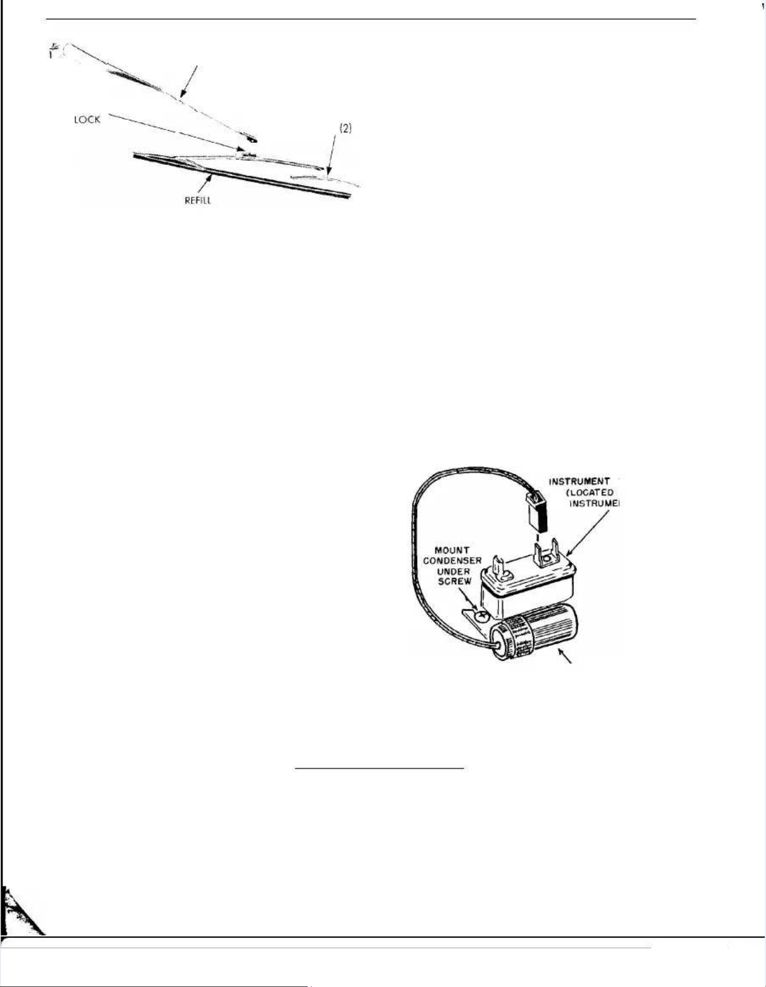
1. WINDSHIELD WIPER ‘BLADE1. WINDSHIELD WIPER ‘BLADE
FILLER REPLACEMENTFILLER REPLACEMENT
RemovalRemoval
( 1) Raise the wiper blade approximately 6 inches( 1) Raise the wiper blade approximately 6 inches
from the windshield and tilt the blade to expose thefrom the windshield and tilt the blade to expose the
arm and blade lock under the wiper arm (Fig. 1).arm and blade lock under the wiper arm (Fig. 1).
(2) Depress the lock lever and disengage the blade(2) Depress the lock lever and disengage the blade
assembly from the wiper arm.assembly from the wiper arm.

88 ACAC CCESESSSOORRIESIES
f f ‘‘\\
WIPER ARMWIPER ARM
//
..
.k.k
WIPER BLADEWIPER BLADE
K N O BK N O B
1212
61 xl 4261 xl 42
Fig. l-wiper Arm and Blade (Disassembled)Fig. l-wiper Arm and Blade (Disassembled)
(3) Holding the blade assembly at the center, de-(3) Holding the blade assembly at the center, de-
press one of the small plastic knobs (Fig. 1).press one of the small plastic knobs (Fig. 1).
(4) With knob depressed, slide the bracket off of(4) With knob depressed, slide the bracket off of
the tension arm and rubber filler.the tension arm and rubber filler.
(5) Withdraw wiper filler from remaining bracket(5) Withdraw wiper filler from remaining bracket
and tension arm assembly. Discard old rubber filler.and tension arm assembly. Discard old rubber filler.
installationinstallation
(1) Insert the new filler into the clamps of the(1) Insert the new filler into the clamps of the
bracket and tension arm assembly.bracket and tension arm assembly.
(2) Slide the mating bracket over the end of the rub-(2) Slide the mating bracket over the end of the rub-
ber filler.ber filler.
(3) With the plastic knob depressed, engage the(3) With the plastic knob depressed, engage the
end of the tension arm into the slots of the bracket andend of the tension arm into the slots of the bracket and
release the knob.release the knob.
(4) Elevate the end of the wiper arm from the wind-(4) Elevate the end of the wiper arm from the wind-
shield and holding the lock lever depressed, engageshield and holding the lock lever depressed, engage
the wiper blade slot over the pivot pin of the wiperthe wiper blade slot over the pivot pin of the wiper
arm.arm.
(5) Release the lock lever and lower blade and arm(5) Release the lock lever and lower blade and arm
assembly to the windshield.assembly to the windshield.
2. W2. WIPER IPER AARM ADJRM ADJ USUSTTMENTMENT
(1) Operate wiper and observe travel and parking(1) Operate wiper and observe travel and parking
position of wiper blade.position of wiper blade.
(2) Loosen wiper arms at pivots.(2) Loosen wiper arms at pivots.
(3) Operate motor several times and turn off wiper(3) Operate motor several times and turn off wiper
switch (Do not use ignition switch), this permits motorswitch (Do not use ignition switch), this permits motor
to stop at normal parking position.to stop at normal parking position.
(4) Position wiper blades at the lower windshield(4) Position wiper blades at the lower windshield
moulding and tighten pivot nuts. (Variable speedmoulding and tighten pivot nuts. (Variable speed
motors only).motors only).
(5(5 jj For single speed motors position wiper bladesFor single speed motors position wiper blades
one inch above moulding and tighten pivot nuts.one inch above moulding and tighten pivot nuts.
(6) Operate wipers and observe travel of both(6) Operate wipers and observe travel of both
blades.blades.
(7) Wet windshield and again operate blades and(7) Wet windshield and again operate blades and
observe wiping pattern.observe wiping pattern.
3. RADIO 3. RADIO CCOONDENSNDENSER ER INSTINSTAALLLLAATTIOIONN
With the use of thermal instrument gauges, a newWith the use of thermal instrument gauges, a new
voltage limiter is mounted on the rear of the instrumentvoltage limiter is mounted on the rear of the instrument
cluster. The voltage limiter reduces battery voltage tocluster. The voltage limiter reduces battery voltage to
approximately 5.0 volts by the means of vibrator points.approximately 5.0 volts by the means of vibrator points.
The The high high senssensitiitivitvity y of of the the radiradio o may may picpick k up up the the arc-arc-
ing of these points and the ing of these points and the addition, of a condenseraddition, of a condenser
will absorb this arcing or static.will absorb this arcing or static.
ThTh e e momounun titi ng ng brbr acackeke t t of of thth e e coco ndnd enen seser r is is slsl otottete dd
and may be inserted under the head of the attachingand may be inserted under the head of the attaching
screw (Fig. 2) without removing the voltage limiter.screw (Fig. 2) without removing the voltage limiter.
The The wire wire lead lead of of the the condenscondenser er is is attacattached hed to to the the prpro-o-
vided output post of the limiter.vided output post of the limiter.
Figures 3 and 4 shows the schematic wiring dia-Figures 3 and 4 shows the schematic wiring dia-
grams for the two model radios.grams for the two model radios.
VOL T AGE LIM IT ERVOLTA GE LIM IT ER
ON REAR OFON REAR OF
NT NT CC LL U S T E R)U ST E R )
CONbENSERCONbENSER
FFig. 2-Radio Cig. 2-Radio C ondeonde nser nser InstInstallaalla tiontion
61X32861X328
aa

ACACCCESESSSOORRIEIESS 99
--

1010 FRFROONT NT SUSUSPSPENSIOENSIONN
Fig. Fig. 4-Ra4-Radio dio WiriWiring Dng Diagriagram (am (ModeModell 109)109)
GROUP 2GROUP 2
FRONT SUSPENSIONFRONT SUSPENSION
The Service Procedures for the Front SuspensionThe Service Procedures for the Front Suspension
Group remain the same as those shown in the 1960Group remain the same as those shown in the 1960
Plymouth Service Manual with the following excep-Plymouth Service Manual with the following excep-
tions :tions :
Front Suspension Height has been changed to 2%Front Suspension Height has been changed to 2%
inches on Suburbans and cars equipped with heavyinches on Suburbans and cars equipped with heavy
duty springs.duty springs.
When installing the torsion bar, be sure the rearWhen installing the torsion bar, be sure the rear
anchor is positioned approximately 60 degrees downanchor is positioned approximately 60 degrees down
from the horizontal (at 4 o’clock position) then engagefrom the horizontal (at 4 o’clock position) then engage
front end of torsion bar in hex opening of lower con-front end of torsion bar in hex opening of lower con-
trol arm until full contact of torsion bar and lower con-trol arm until full contact of torsion bar and lower con-
trol arm shaft is made. Install lock ring in rear of reartrol arm shaft is made. Install lock ring in rear of rear
anchor, then move torsion bar rearward until it con-anchor, then move torsion bar rearward until it con-
tacts the lock ring. After installing adjusting bolts, seattacts the lock ring. After installing adjusting bolts, seat
and swivel, adjust Front Suspension Height as neces-and swivel, adjust Front Suspension Height as neces-
sary.sary.
Figure 1 shows an exploded view of the Front Sus-Figure 1 shows an exploded view of the Front Sus-
pension.pension.
MODELS . . . , , . . . . .MODELS . . . , , . . . . .
STEERING AXIS INCLINATION.STEERING AXIS INCLINATION.
C A M B E R . . . . . . . . . . . . . . . . . . . . .C A M B E R . . . . . . . . . . . . . . . . . . . . .
CASTER (Manual Steering) . .CASTER (Manual Steering) . .
(Power Steering) . .(Power Steering) . .
TOE-IN . . . . . . . . . . . . . . . .TOE-IN . . . . . . . . . . . . . . . .
SPEClFlCATlONSSPEClFlCATlONS
RP1-RP2RP1-RP2
. . . . . . . . . . . . . . . . . . . . .. . . . . . . . . . . . . . . . . . . . .
. , , . . . , . . . . . . . . . . . . .. , , . . . , . . . . . . . . . . . . .
sl/z” sl/z”
toto
71/2”71/2”
. . . . . . . . . . . . . . . .. . . . . . . . . . . . . . . .
**
. . .. LeftLeft
++
‘/2”‘/2”
ff
1/d”1/d”
(+(+
‘/2”‘/2”
Preferred)Preferred)
RightRight
+1/4O+1/4O
kk
1/4’1/4’
+1/4’+1/4’
Preferred) Preferred)
. . . . . , . . . . . . . .. . . . . , . . . . . . . .
Y2”Y2”
ILIL
Y2”Y2”
. . . . . . . . . . . . . . . . . . .. . . . . . . . . . . . . . . . . . .
+ + “1“1
?h”?h”
. . . . . . . . . . . . . . . . . . . . . . . . . . .. . . . . . . . . . . . . . . . . . . . . . . . . . .
&&
inch toinch to
55
inchinch
(l/s(l/s
inch Preferred) inch Preferred)

FRFROONT NT SUSSUSPENSIOPENSIONN 1111
SPECIFICATIONS (Cont’d)SPECIFICATIONS (Cont’d)
TOE-OUT ON TURNS.TOE-OUT ON TURNS. . . . .. . . .
211,~” 211,~”
(Al’)(Al’)
Inner Wheel, Inner Wheel,
When Outer Wheel isWhen Outer Wheel is
20”20”
TREADTREAD
Front . . . . . . . . .Front . . . . . . . . .
Rear. . . .Rear. . . .
W H E E L B A S E ( I n c h e s )W H E E L B A S E ( I n c h e s )
Suburban Models (Inches),Suburban Models (Inches),
C - 4 8 5 .C - 4 8 5 .
c-3409..c-3409..
c-3479.c-3479.
c-3553..c-3553..
C - 3 5 5 6 .C - 3 5 5 6 .
C-3560..C-3560..
60.960.9
.................... ,, . . . .. . . . .. .. .. .. .. .. .. .. .. .. .. .. .. 5599..77
............................................................ 118118
.. .. .. .. .. .. .. .. .. .. .. .. .. .. .. .. .. .. .. .. .. .. .. .. .. .. .. 122122
SPECIAL TOOLSSPECIAL TOOLS
Torque Wrench--Foot PoundsTorque Wrench--Foot Pounds
Gauge-Camber and CasterGauge-Camber and Caster
G a u g e a n d S c r i b e r - T o e - I nG a u g e a n d S c r i b e r - T o e - I n
Remover and Installer-Shock Absorber Lower BushingRemover and Installer-Shock Absorber Lower Bushing
(All Models)(All Models)
Installer-Lower Control Arm BushingInstaller-Lower Control Arm Bushing
Wrench (socket)- Ball Joint Assembly to Upper andWrench (socket)- Ball Joint Assembly to Upper and
Lower Control ArmLower Control Arm
C-3564 .C-3564 .
C - 3 6 0 8 .C - 3 6 0 8 .
C - 3 6 6 9C - 3 6 6 9
C-3675 .C-3675 .
C - 3 6 9 6C - 3 6 9 6
c-3710 . .c-3710 . .
(All Models)(All Models)
DDDD--434355.. .. .. .. .. .. .. .. .. TTururnntatabble le ~-~-WhWheeeel l AAlliiggnniinngg
SPSP-3-323233A3A.. .. .. .. .. .. .. AdAdapapteter-r-UUse se wiwith th ToTool Col C-3-3666699
Remover-Ball Joint Stud (All Models)Remover-Ball Joint Stud (All Models)
Gauge-Front End Height and LevelGauge-Front End Height and Level
Remover and Installer-Upper Control Arm BushingRemover and Installer-Upper Control Arm Bushing
Wrench, Camber and Caster Adjusting (long)Wrench, Camber and Caster Adjusting (long)
Wrench, Camber and Caster Adjusting (short)Wrench, Camber and Caster Adjusting (short)
Upper Control Arm Bushing Remover and InstallerUpper Control Arm Bushing Remover and Installer
TORQUE REFERENCETORQUE REFERENCE
Ball Joint in Control Arms.Ball Joint in Control Arms. .. .. .. .. .. .. .. .. .. .. .. .. .. .. .. .. .. .. .. .. .. .. .. .. .. .. .. .. .. .. .. .. .. .. .. .. .. .. .. ..
Lower Ball Joint Stud.Lower Ball Joint Stud. ............................................................................................
Upper Ball Joint StudUpper Ball Joint Stud . .. . .. . .. . . .. . . .. . .. . .. . .. . .. . .. . .. . .. . .. . .. . .. . .. . .. . . .. . . .. . . .. . . .. . .. . .. . .. . .. . .. . .. .
Lower Control ArmLower Control Arm
Bumper Nut.Bumper Nut. ....................................................................................................
Shaft Nut OuterShaft Nut Outer
3/i.3/i.
........................................................................................
InnerInner
s/8.s/8.
........................................................................................
Strut Bolt Nut.Strut Bolt Nut. ..................................................................................................
Strut Bushing Nut.Strut Bushing Nut. ..........................................................................................
Upper Control ArmUpper Control Arm
Bumper Nut.Bumper Nut. ....................................................................................................
Support Bracket Cam Bolt NutSupport Bracket Cam Bolt Nut ....................................................................
Sway Eliminator ShaftSway Eliminator Shaft
Cushion Retainer Bolt Nut.Cushion Retainer Bolt Nut. ............................................................................
Frame Bracket Screw.Frame Bracket Screw. ....................................................................................
Link Nut.Link Nut. . .. . . .. . . .. . . .. . . .. . . .. . . .. . . .. . . .. . . .. . . .. . . .. . . .. . . .. . . .. . . .. . .. . .. . . .. . . .. . . .. . . .. . . .. . . .. . . .. . . .. . ..
Front Shock AbsorberFront Shock Absorber
Upper Mounting Nut.Upper Mounting Nut. ..................................................................................
Lower Mounting Nut.Lower Mounting Nut. ......................................................................................
Steering Knuckle to Brake Support Bolt.Steering Knuckle to Brake Support Bolt. . . . . . . . . . . . . . . . . . . . . . . . . . .. . . . . . . . . . . . . . . . . . . . . . . . . .
Steering Knuckle to Steering Knuckle Arm Nut.Steering Knuckle to Steering Knuckle Arm Nut. ..................................
Foot-PoundsFoot-Pounds
125 Min.125 Min.
135135
100100
Inch-PoundsInch-Pounds
2020 00
1818 00
1010 00
100100
5050
200200
6565
3535
150150
100100
2525
5555
5555
5050

AXLE REARAXLE REAR 1313

AXLE-REARAXLE-REAR 1313
GROUP 3GROUP 3
REAR AXLEREAR AXLE
The Service Procedures for the Rear Axle GroupThe Service Procedures for the Rear Axle Group re-re- ice Manual except for the procedures listed in thisice Manual except for the procedures listed in this
main main the the samsame ae as os outlutlineined id in tn the he 1961960 P0 Plymlymoutouth Sh Serverv-- SupSuppleplemenment.t.
TYPE.TYPE.
DRIVE GEAR TYPE, . .DRIVE GEAR TYPE, . .
RATIOSRATIOS
Manual Three-Speed. .Manual Three-Speed. .
Optional-Mountain Ratio.Optional-Mountain Ratio.
T o r q u e F l i t e S i x .T o r q u e F l i t e S i x .
Optional-Mountain Ratio.Optional-Mountain Ratio.
PowePowerFlirFlite te ..
Optional-Mountain Ratio.Optional-Mountain Ratio.
TToorrqquueeFFlliitte Ee E ii gg hh tt ..
A v a i l a b l e .A v a i l a b l e .
R I N G G E A R S I Z E .R I N G G E A R S I Z E .
SPECIFICATIONSSPECIFICATIONS
RP-1RP-1
225 Cu. In.225 Cu. In.
RP-2RP-2 RP-2RP-2
33118 8 CCuu. . IInn.. 33661 1 CCuu. . IInn..
Semi-FloatingSemi-Floating
HypoidHypoid
RAM MAN.RAM MAN.
383 Cu. In.383 Cu. In.
Conv.Conv. SSuurree--GGrriipp CCoonnvv.. SSuurree--GGrriipp
33..5555** 33..5588 33..5588 33..5588
33..9911 33..9911
3.313.31 3.58 3.58
3.553.55
3.313.31 3.583.58
3.583.58
2.93 2.932.93 2.93
33..3311 33..5588
81/481/4
in. in.
****
Conv. Sure-GripConv. Sure-Grip
3.313.31 3.583.58
3.313.31
ii3ii3
2.932.93 3.583.58
8833//
in.in.
Conv.Conv.
3.233.23
..
3%3%
.006.006
to to .009 .009 incinchh
.OOO.OOO toto 903903 inch inch
RING GEAR TO DRIVE PINIONRING GEAR TO DRIVE PINION
CLEARANCECLEARANCE
(at point of minimum backlash)(at point of minimum backlash)
DIFFERENTIAL CASE RUN-OUTDIFFERENTIAL CASE RUN-OUT
DIFFERENTIAL SIDE GEARDIFFERENTIAL SIDE GEAR
C L E A R A N C EC L E A R A N C E .. ,001 ,001 to to .012 inch.012 inch
A X L E S H A F T E N D P L A Y . .A X L E S H A F T E N D P L A Y . . ,013 to ,013 to ,023 in,023 inchch
DRIVE PINION BEARING PRELOADDRIVE PINION BEARING PRELOAD 20-30 in. lbs. without seal20-30 in. lbs. without seal
L U B R I C A N T C A P A C I T Y ( P I N T S ) .L U B R I C A N T C A P A C I T Y ( P I N T S ) .
33
(6(6
Cyl.1Cyl.1
*83*83// 44
in. Ring Gear and 3.31 Ratio-Standard on 6 Cyl. Taxicab and Heavy Duty Packagein. Ring Gear and 3.31 Ratio-Standard on 6 Cyl. Taxicab and Heavy Duty Package
**83**83// 44
in. in. Ring Ring GeGearar - - StanStandard on 6 Cydard on 6 Cyl. Cars witl. Cars with Sure-h Sure-Grip AGrip Axlesxles
3%3%
88
Cyl.1Cyl.1
SPECIAL TOOLSSPECIAL TOOLS
C-C-292292.F.F2.2. .. .. .. .. .. .A.Axlxle, e, PiPininion aon and Dnd Dififfefererentntiaial Cal Case Rse Rololleler Ber Beararining Pug Pullller Ser Setet
C-C-40406-6-A.A. .. .. .. .. .. .. .. DiDiffffererenentitial Bal Beaeariring Ang Adjdjusustiting Wng Wrerencnchh
C-413.C-413. ................ .Rear .Rear Axle Shaft OutAxle Shaft Outer Bearing Cup er Bearing Cup DriverDriver
C-C-45452,2, .. .. .. .. .. .. .. .. .. UUnniviverersasal l JJoioinnt t FlFlaannge ge PuPulllleerr
C-485.C-485. .................. Torque Wrench (Foot-Pounds)Torque Wrench (Foot-Pounds)
1144 AXLE-REARAXLE-REAR

1144 AXLE-REARAXLE-REAR
SSPPECECIAIAL TL TOOOOLLS (CS (Cont’d)ont’d)
C-496. Pinion and Transmission Companion Flange or Yoke PullerC-496. Pinion and Transmission Companion Flange or Yoke Puller
C-499. .AxlC-499. .Axle e Shaft Shaft PullerPuller
C - 6 3 7 . A x l e S h a f t a n d I n n e r O i l S e a l P u l l e rC - 6 3 7 . A x l e S h a f t a n d I n n e r O i l S e a l P u l l e r
CC--668855 I n c h - P oI n c h - P o u n d u n d T o r q u e T o r q u e W r e n c hW r e n c h
C - 7 4 5 R e a r A x l e S h a f t O i l S e a l I n s t a l l i n g S l e e v eC - 7 4 5 R e a r A x l e S h a f t O i l S e a l I n s t a l l i n g S l e e v e
C - 7 5 8 - D 3C - 7 5 8 - D 3 Pinion Setting Gauge SetPinion Setting Gauge Set
CC -- 88 33 99 .. R eR ea r a r A xA xl e l e S hS ha fa ft It In nn ne r e r O iO il Sl Se ae al Dl Dr ir iv everr
CC -- 88 44 55 .. UUnniivveerrssaal l WWhheeeel l aannd d HHuub b PPuulllleerr
C - 3 0 0 5 . . F o o t - P o u n d T o r q u e W r e n c hC - 3 0 0 5 . . F o o t - P o u n d T o r q u e W r e n c h
CC -- 33 22 11 44 .. ..PPiinniioon On Oiil l SSeeaal l PPuulllleerr
CC -- 33 22 88 11 C oC om pm pa na ni oi on n F lF la na ng e g e H oH ol dl di ni ng Wg Wr er en cn chh
C -C - 3 33 3 3 93 9 . . ..DDiiaal Il I n d in d i c ac a t o rt o r
C - 3 5 6 5 A x l e S h a f t O u t e r S e a l D r i v e rC - 3 5 6 5 A x l e S h a f t O u t e r S e a l D r i v e r
C - 3 6 5 6 . P i n i o n O i l S e a l D r i v e rC - 3 6 5 6 . P i n i o n O i l S e a l D r i v e r
D DD D - 9- 9 9 6 9 6 ..PPiinniioon B en B e a ra r i ni n g I ng I n s ts t a la l l el e rr
D D - 9D D - 99 9 .9 9 . ..FFllaanngge e o r Y o k e I n s to r Y o k e I n s ta l l e ra l l e r
D D - 1 0 0 5 .D D - 1 0 0 5 . Differential Case Side and Cross Shaft Roller Bearing DriverDifferential Case Side and Cross Shaft Roller Bearing Driver
D D - 1D D - 1 014 . .0 1 4 . .RReeppaaiir r St a nS t a n d - Did - D i f f e rff e r en t i ae n t ia l C a rl C a r r i e rr i e r
TTOORQRQUE RUE REFEFERERENCENCEE
(Foot-Pounds)(Foot-Pounds)
AA x lx l e e SS hh aa ff t t NN uu tt ss .. . . . . . . .. ..
BraBrake ke SupSupporport t PlaPlate te to to HouHousinsing g MouMountinting ng BolBolt t NutNutss . . . . . . ..
Differential Carrier to Axle Housing Bolt Nuts. . .Differential Carrier to Axle Housing Bolt Nuts. . .
R e a r A x l e D r i v e G e a r t o C a s e B o l t s . .R e a r A x l e D r i v e G e a r t o C a s e B o l t s . . . . . . . .. . . . . .
DDiiffffeerreennttiiaal l BBeeaarriinng g CCaap p BBoollttss.. . . . . . . . . ..
Rear Axle Drive Pinion Companion Flange Nut.Rear Axle Drive Pinion Companion Flange Nut. .. . . . . . . ..
145 (Min.)145 (Min.)
30 to 3530 to 35
4545
4545
9090
240 (Min.)240 (Min.)
1. REAR AXLE SHAFT END PLAY1. REAR AXLE SHAFT END PLAY
Axle shaft end play is .01Axle shaft end play is .013 3 to to .023 inch. A minimum.023 inch. A minimum
ofof .013.013 inch end play is required since a loss of end inch end play is required since a loss of end
play results when the axle housing and axle shaft ex-play results when the axle housing and axle shaft ex-
pand by different amounts during warm up. Less thanpand by different amounts during warm up. Less than
.013.013 inch end play can result in excessive bearing inch end play can result in excessive bearing pre-pre-
load, under this condition, causing shorter bearing life.load, under this condition, causing shorter bearing life.
2. DRIVE GEAR AND PINION BACKLASH2. DRIVE GEAR AND PINION BACKLASH
The drive gear and pinion backlash should be .006The drive gear and pinion backlash should be .006
to .009 inch at point of minimum backlash.to .009 inch at point of minimum backlash.
3. PINION BEARING PRELOAD3. PINION BEARING PRELOAD
If the original pinion bearing is to be reinstalled, theIf the original pinion bearing is to be reinstalled, the
preload setting should be as follows:preload setting should be as follows:
Minimum Drag Torque-Zero, but with no end play.Minimum Drag Torque-Zero, but with no end play.
Maximum Drag Torque-13 inch-pounds.Maximum Drag Torque-13 inch-pounds.
4. PINION PRE-LOAD (Pinion with Spacer)4. PINION PRE-LOAD (Pinion with Spacer)
The illustration used in the 1960 Service Manual onThe illustration used in the 1960 Service Manual on
Page 11, Figure 20, was incorrect. The correct illustra-Page 11, Figure 20, was incorrect. The correct illustra-
tion is shown here (Fig. 1).tion is shown here (Fig. 1).
The rear axle used on Plymouth cars equipped withThe rear axle used on Plymouth cars equipped with
a 383 cubic inch engine, incorporates a drive pinion nota 383 cubic inch engine, incorporates a drive pinion not
using a pinion shaft spacer. When setting the Pinionusing a pinion shaft spacer. When setting the Pinion
Depth of Mesh and Pinion Bearing Pre-Load, proceedDepth of Mesh and Pinion Bearing Pre-Load, proceed
in the sequence as follows:in the sequence as follows:
5. PINION WITHOUT BEARING SPACER5. PINION WITHOUT BEARING SPACER
INSTALLATION USING TOOLINSTALLATION USING TOOL C-758-D3C-758-D3
(Fig. 2)(Fig. 2)
Depth of MeshDepth of Mesh
The position of the drive pinion with respect to theThe position of the drive pinion with respect to the
ring gear (depth of mesh) is determined by the loca-ring gear (depth of mesh) is determined by the loca-
tion of the bearing cup shoulders in the carrier andtion of the bearing cup shoulders in the carrier and
by the thrust portion of the pinion in back of the rearby the thrust portion of the pinion in back of the rear
bearing. The thickness of a pinion spacer washer suit-bearing. The thickness of a pinion spacer washer suit-
able for the carrier can be determined by using Toolable for the carrier can be determined by using Tool
C-7.58.D3.C-7.58.D3.
(1) Install the pinion locating spacer SP-2921 on the(1) Install the pinion locating spacer SP-2921 on the
main body of Tool C-758. Place large end of rear bear-main body of Tool C-758. Place large end of rear bear-
ing over shoulder of spacer and insert tool in the car-ing over shoulder of spacer and insert tool in the car-
rier.rier.
(2) Place front bearing (small end down), com-(2) Place front bearing (small end down), com-
pression sleeve SP-535, centralizing washer SP-534 andpression sleeve SP-535, centralizing washer SP-534 and
compression nut SP-533 on the main body.compression nut SP-533 on the main body.
(3) With the nose of the carrier up, place flange(3) With the nose of the carrier up, place flange
AXLE-REARAXLE-REAR 1515

PINION PINION LOCLOCATING WASHEATING WASHER OR SHR OR SHIMIM
---L-11---L-11
bb
ASSEMBLASSEMBLY OY OF SF SP-P-526526
‘ i‘ i
VV SPSP--17301730 57x 15257x 152
Fig. l-Fig. l- Setting Pinion BeSetting Pinion Beaaring Pre-ring Pre-Load Load with Twith Tooool l C-7C-75588-D-D22-3-3
holding Tool C-3281 on the compression sleeve. Allowholding Tool C-3281 on the compression sleeve. Allow
the assembly to rotate while tightening the nut 25 tothe assembly to rotate while tightening the nut 25 to
35 inch pounds torque.35 inch pounds torque.
(4) Rotate the tool several times in each direction(4) Rotate the tool several times in each direction
to align the bearing rollers and recheck the torque.to align the bearing rollers and recheck the torque.
(5) With the proper pre-load on the bearings, invert(5) With the proper pre-load on the bearings, invert
the carrier in the stand. Install gauge block SP-528 inthe carrier in the stand. Install gauge block SP-528 in
the end of thethe end of the too1too1 with allen with allen scscrewrew..
(6) Position arbor SP-561 (part of Tool C-758) in the(6) Position arbor SP-561 (part of Tool C-758) in the
differential bearing pedestals of the carrier. Center thedifferential bearing pedestals of the carrier. Center the
arbor so that an approximate equal distance is main-arbor so that an approximate equal distance is main-
tained at both ends.tained at both ends.
(7) Position the differential bearing caps and attach-(7) Position the differential bearing caps and attach-
ing bolts on the carrier pedestals.ing bolts on the carrier pedestals.
(8)(8) BetweenBetween the arbor and each cap, insert a piece the arbor and each cap, insert a piece
ofof .002.002 inch feeler stock. Tighten the cap attaching bolts inch feeler stock. Tighten the cap attaching bolts
securely.securely.
(9) Select a washer that will fit between the tool(9) Select a washer that will fit between the tool
gauge block and arbor. This fit must be snug but notgauge block and arbor. This fit must be snug but not
too tight, similar to the pull too tight, similar to the pull of a feeler gauge. Thisof a feeler gauge. This
washer is suitable for measurement, not for installa-washer is suitable for measurement, not for installa-
tion .t io n.
(10) To select a (10) To select a washer for installation, read thewasher for installation, read the
marking on the end of the marking on the end of the pinion (-0, -1, -2, pinion (-0, -1, -2, ++11
+2,+2, etc.) when the marking is etc.) when the marking is addadd that amountthat amount
to the thickness of the washer selected in step (9).to the thickness of the washer selected in step (9).
When the marking isWhen the marking is ++,, subtract subtract that amount. Ex-that amount. Ex-
ample: With a washerample: With a washer .086.086 inch thick and a pinioninch thick and a pinion
marked -2, installmarked -2, install aa washerwasher .088.088 inch thickinch thick (.086(.086 ++
.002.002 ==.088)..088). Exumple: With a washerExumple: With a washer ,086,086 inch thickinch thick
and a pinion and a pinion marked +2, install a marked +2, install a washerwasher .084.084 inchinch
thickthick (.086(.086 -- .002.002 == ,084) or when a washer ,084) or when a washer ,086,086
inch thick is too loose andinch thick is too loose and .088.088 inch too tight, use inch too tight, use .088.088
and the pinion marking.and the pinion marking.
(11) Remove the differential bearing caps and ar-(11) Remove the differential bearing caps and ar-
bor from the carrier.bor from the carrier.
ASSEMB1.YASSEMB1.Y
y Jy J ,,--
OFOF
SPSP--5; 65; 6
JJ
ii
II
-- --
TTIGIGHTHTEN GEN GAUGAUG E TE TOO
qq
40-50 FOOT POUNDS AND DETERMINE40-50 FOOT POUNDS AND DETERMINE
PINION PINION LLOOCCATING WASHEATING WASHERR 0NI.Y0NI.Y 60X16860X168
Fig. 2-SeFig. 2-Setting Ptting Pinioinion Bn Beaea ring Prring Pre-e-LoaLoad with d with TTooool l C-7C-75588-D-D33
1616 BRAKESBRAKES

(12) Reverse the carrier in the stand so the nut of(12) Reverse the carrier in the stand so the nut of
the tool is up and leave tool in the tool is up and leave tool in carrier, ready for bear-carrier, ready for bear-
ing preloading.ing preloading.
(13) While supporting the lower portion of the tool(13) While supporting the lower portion of the tool
in the carrier with one hand, remove the tool nut, toolin the carrier with one hand, remove the tool nut, tool
centering washer and compression sleeve. Lower thecentering washer and compression sleeve. Lower the
tool down and out of carrier.tool down and out of carrier.
((14) Remove the pinion front bearing cone from the14) Remove the pinion front bearing cone from the
carrier.carrier.
Pinion Bearing Pre-LoadPinion Bearing Pre-Load
(1) Place spacer SP-2921 on main body of Tool(1) Place spacer SP-2921 on main body of Tool
C-758 with the shoulder up. Place the selected pinionC-758 with the shoulder up. Place the selected pinion
spacer, spacer sleeve SP-2920 and the rear bearing onspacer, spacer sleeve SP-2920 and the rear bearing on
the tool.the tool.
(2) Insert the tool in carrier, install the(2) Insert the tool in carrier, install the orlgmalorlgmal shim shim
pile and the front bearing. Install the compressionpile and the front bearing. Install the compression
sleeve SP-535 (square hole down), centralizing washersleeve SP-535 (square hole down), centralizing washer
SP-534 and tool nut SP-535.SP-534 and tool nut SP-535.
(3) Tighten tool nut to 240 foot-pounds using holding(3) Tighten tool nut to 240 foot-pounds using holding
Tool Tool C-3281 C-3281 on thon the compe compression ression sleeve sleeve to hoto hold thld the as-e as-
sembly in several positions to make a complete revolu-sembly in several positions to make a complete revolu-
tion while tightening. Remove holding tool and rotatetion while tightening. Remove holding tool and rotate
assembly several turns in both directions to align theassembly several turns in both directions to align the
bearing rollers. Re-check torque to 240 foot-poundsbearing rollers. Re-check torque to 240 foot-pounds
(torque may have diminished as bearing rollers were(torque may have diminished as bearing rollers were
aligned by rotating).aligned by rotating).
(4) Correct bearing pre-load readings can only be(4) Correct bearing pre-load readings can only be
obtained with the nose of the carrier up. Useobtained with the nose of the carrier up. Use inch-inch-
pound torque wrench, C-685. With the handle of thepound torque wrench, C-685. With the handle of the
wrench floating, read the torque when the wrench iswrench floating, read the torque when the wrench is
moving through at least one full rotation. Correct read-moving through at least one full rotation. Correct read-
ing is 20 to 30 inch-pounds (without seal) and shoulding is 20 to 30 inch-pounds (without seal) and should
be uniform during the full rotations. If bearing pre-loadbe uniform during the full rotations. If bearing pre-load
is more than 30 inch-pounds, a thicker shim should beis more than 30 inch-pounds, a thicker shim should be
used under front bearing. If the bearing pre-load is lessused under front bearing. If the bearing pre-load is less
than 20 inch-pounds, a thinner shim should be used.than 20 inch-pounds, a thinner shim should be used.
Shims are available in thicknesses ofShims are available in thicknesses of .OlO,.OlO, .012,.012, .014.014
.016.016andand .018.018inch.inch.
(5) Remove the tool with shim pack, bearing cone,(5) Remove the tool with shim pack, bearing cone,
pinion locating washer, and spacer from the carrier andpinion locating washer, and spacer from the carrier and
the tool.the tool.
(6) Install the correct washer on the pinion shaft.(6) Install the correct washer on the pinion shaft.
The washeThe washer has a r has a chamfer ochamfer on one n one side.side. This chamferThis chamfer
must face the pinion gear thrust surface.must face the pinion gear thrust surface.
(7) Position the rear bearing cone on the pinion(7) Position the rear bearing cone on the pinion
shaft (small side away from the pinion gear). Makeshaft (small side away from the pinion gear). Make
certain the contacting surfaces of the correct washer,certain the contacting surfaces of the correct washer,
pinion pinion gear,gear, and cand contactiontacting surng surface face of rear of rear bearingbearing
cone are perfectly clean and free of any foreign par-cone are perfectly clean and free of any foreign par-
ticles. Install the rear bearing cone onto pinion shaftticles. Install the rear bearing cone onto pinion shaft
with Tool DD-996.with Tool DD-996.
(8) Install the selected shim pack.(8) Install the selected shim pack.
(9) Lubricate front and rear pinion bearings with(9) Lubricate front and rear pinion bearings with
heavy oil.heavy oil.
(10) Insert the pinion shaft up through the carrier(10) Insert the pinion shaft up through the carrier
and install the front bearing.and install the front bearing.
( 11) Install the oil seal in carrier with driver C-3656( 11) Install the oil seal in carrier with driver C-3656
with lip of seal toward the bearing.with lip of seal toward the bearing.
(12) Start the companion flange on the pinion shaft,(12) Start the companion flange on the pinion shaft,
completing the installation of the companion flangecompleting the installation of the companion flange
with installing Tool C-496 or DD-999. with installing Tool C-496 or DD-999. Remove the tool.Remove the tool.
(13) Install the plain washer (concave side of(13) Install the plain washer (concave side of
washer down) and nut. Hold companion flange withwasher down) and nut. Hold companion flange with
holding Tool C-3281 and tighten nut to 240 foot-poundsholding Tool C-3281 and tighten nut to 240 foot-pounds
torque. Rotate the assembly several times in both di-torque. Rotate the assembly several times in both di-
rections to align the bearing rollers. rections to align the bearing rollers. Recheck torque toRecheck torque to
240 foot-pounds (torque may have diminished as bear-240 foot-pounds (torque may have diminished as bear-
ing rollers were aligned by rotating).ing rollers were aligned by rotating).
GROUP 4 AND 5GROUP 4 AND 5
PARKING AND SERVICE BRAKESPARKING AND SERVICE BRAKES
Servicing Procedures for the 1961 Model parkingServicing Procedures for the 1961 Model parking
and service brakes remain the same as outlined in theand service brakes remain the same as outlined in the
1960 Plymouth Service Manual except as listed in this1960 Plymouth Service Manual except as listed in this
Supplement.Supplement.
(a) Parking brake pedal and release handle.(a) Parking brake pedal and release handle.
(b) Fitting and aligning brake shoes.(b) Fitting and aligning brake shoes.
(c) Police-Special service brakes.(c) Police-Special service brakes.
(d) Brake bleeding procedure.(d) Brake bleeding procedure.
(e ) Service brake adjustment.(e ) Service brake adjustment.
BRAKESBRAKES 1177

SPECIFICATIONSSPECIFICATIONS
SERVICE BRAKESERVICE BRAKE
TYPE. . . . . . . . . . . . . . . . . . . . . . . . .TYPE. . . . . . . . . . . . . . . . . . . . . . . . .
DRUM DIAMETER (Front-Rear)DRUM DIAMETER (Front-Rear) ..............................................................
(Police Special).(Police Special). ................................................................................
LINING TYPELINING TYPE ..............................................................................................
(Police Special).(Police Special). ..................................................................................
Method of Attachment.Method of Attachment. ....................................................................
T h i c k n e s sT h i c k n e s s ..................................................................................
Width-(118” Wheelbase)Width-(118” Wheelbase) ................................................................
(Police Special).(Police Special). ..................................................................................
(122” Wheelbase, Suburban Model)(122” Wheelbase, Suburban Model) ................................................
BRAKE SHOE RETURN SPRING TENSION POUNDSBRAKE SHOE RETURN SPRING TENSION POUNDS
(Front and Rear)(Front and Rear) ..................................................................................
PERCENT OF BRAKING TORQUEPERCENT OF BRAKING TORQUE
(Front)(Front) ....................................................................................................
((RReeaarr)) . .. . . .. . . .. . . .. . ..
DIAMEDIAMETER OF WHEETER OF WHEEL CYLINDERL CYLINDER BOREBORE
........................................................................................
DIAMETER OF MASTER CYLINDER BORE.DIAMETER OF MASTER CYLINDER BORE. ........................................
PISTON CYLINDER CLEARANCE (All Bores).PISTON CYLINDER CLEARANCE (All Bores). ..................................
BRAKE PEDAL FREE PLAY (Manual Brakes)BRAKE PEDAL FREE PLAY (Manual Brakes) ........................................
BRAKE PEDAL FREE PLAY (Power Brakes)BRAKE PEDAL FREE PLAY (Power Brakes) ........................................
PARKING BRAKEPARKING BRAKE
TYPE (Automatic Transmission)TYPE (Automatic Transmission) . . . . . . . . . . . . . . . . . . . . . . . . . . . . . . . .. . . . . . . . . . . . . . . . . . . . . . . . . . . . . . . .
(Manual Transmission)(Manual Transmission) ..................................................................
L O C A T I O NL O C A T I O N . . . . ..
DRUM DIAMETER (Automatic Transmission)DRUM DIAMETER (Automatic Transmission)
(Manual Transmission).(Manual Transmission).
L I N I N G T Y P E ( E x t e r n a l ) .L I N I N G T Y P E ( E x t e r n a l ) .
(Internal) . .(Internal) . .
WIDTH. . .WIDTH. . .
THICKNESS. . . . . .THICKNESS. . . . . .
L I N I N G T O D R U M C L E A R A N C E . .L I N I N G T O D R U M C L E A R A N C E . .
CC--665500.... BBlleeeeddeer r HHoossee
cc--774455.. SSeeaal l PPrrootteeccttoorr
CC--883377BB.. FFiilllleer r ((WWhheeeell))
CC -- 88 44 55 .. PPuulllleer r ((WWhheeeell))
CC--33008800.. HHoonne e ((WWhheeeel l CCyylliinnddeerr))
c - 3 2 2 9c - 3 2 2 9 Pliers (Power Brakes)Pliers (Power Brakes)
CC334499AA AAddaapptteer r ((BBlleeeeddeerr))
..
..
..
SPECIAL TOOLSSPECIAL TOOLS
C-3496C-3496
C-3508.C-3508.
C-3512.C-3512.
C-3578.C-3578.
c-3579.c-3579.
MT-19-HMT-19-H
TORQUE REFERENCETORQUE REFERENCE
Hydraulic-Total ContactHydraulic-Total Contact
Internal ExpandingInternal Expanding
11”11”
1122””
Molded AsbestosMolded Asbestos
Molded Metal Embedded AsbestosMolded Metal Embedded Asbestos
CyclebondCyclebond
‘ X 4 ”‘ X 4 ”
2” Front 2” Rear2” Front 2” Rear
21/z”21/z”
Fron t Fron t
21/z”21/z”
Rear Rear
21/2”21/2”
Front 2” Rear Front 2” Rear
45 to 5545 to 55
6060
40%40%
11
l/8”l/8”
11
‘/8”‘/8”
,003”,003”
toto
.0065”.0065”
Not RequiredNot Required
‘/6’‘/6’
t0t0
l/g”l/g”
Internal ExpandingInternal Expanding
External ContractingExternal Contracting
Rear of TransmissionRear of Transmission
7 inch7 inch
6 inch6 inch
Woven Compressed AsbestosWoven Compressed Asbestos
Moulded AsbestosMoulded Asbestos
2 inch2 inch
5/325/32
inch inch
.015.015
toto
.020.020
inch inch
P a r k i n g B r a k e C a b l e B r a c k e t B o l t .P a r k i n g B r a k e C a b l e B r a c k e t B o l t .
Parking Brake Lever to Instrument Panel.Parking Brake Lever to Instrument Panel.
..
..
..
Parking Brake Adjusting Bolt Cover, Bolt.Parking Brake Adjusting Bolt Cover, Bolt.
..
Parking Brake Drum Flange Bolt NutParking Brake Drum Flange Bolt Nut
s6.s6.
..
3/83/8
. .. .
..
..
..
..
7 5 6 . .7 5 6 . .
Foot-PoundsFoot-Pounds
2200
2200
3535
5050
Rear Wheel Brake Support to Axle Housing, . . . . . . . . . .Rear Wheel Brake Support to Axle Housing, . . . . . . . . . . 3535
Tank (Bleeder)Tank (Bleeder)
Gauge [Power Brakes)Gauge [Power Brakes)
WrenchWrench
Ring (Power Brakes)Ring (Power Brakes)
Pilot (Power Brakes)Pilot (Power Brakes)
Brake Shoe GaugeBrake Shoe Gauge
Inch-PoundsInch-Pounds
130130
9955

CCLLUUTTCCHH 1199
or stands back off the brake shoe adjusting cams toor stands back off the brake shoe adjusting cams to 5 BRAKE SHOE ADJUSTMENT5 BRAKE SHOE ADJUSTMENT

or stands, back off the brake shoe adjusting cams toor stands, back off the brake shoe adjusting cams to
the fully released position. (Wheel cylinder cups willthe fully released position. (Wheel cylinder cups will
contract and compress trapped air in the bleeder screwcontract and compress trapped air in the bleeder screw
area).area).
(4) Clean the dirt from all wheel cylinder bleeder(4) Clean the dirt from all wheel cylinder bleeder
valves.valves.
(5) Attach brake bleeder hose C-650 to the bleeder(5) Attach brake bleeder hose C-650 to the bleeder
valve of each wheel cylinder as they are bled.valve of each wheel cylinder as they are bled.
(6) Place open end of bleeder hose in an uncon-(6) Place open end of bleeder hose in an uncon-
taminated clear jar. (Clean fluid may be reused).taminated clear jar. (Clean fluid may be reused).
CAUTION:CAUTION: WaterWater and any type of mineraland any type of mineral
oil derivative such as gasoline, engine oil,oil derivative such as gasoline, engine oil,
etc.,etc., will cwill contamontaminatinate bre brake fake fluid. luid. It is It is ex-ex-
tremelytremely important that the container used toimportant that the container used to
catch the brake fluidcatch the brake fluid bebe clean, free from mois-clean, free from mois-
ture and must never have contained mineralture and must never have contained mineral
oil in anyoil in any form.form.
(7) Open brake bleeder and bleed for a minimum(7) Open brake bleeder and bleed for a minimum
of thirty seconds with a constant air pressure of twentyof thirty seconds with a constant air pressure of twenty
five pounds in bleeder tank.five pounds in bleeder tank.
(8) Bleed all wheel cylinders in the following order.(8) Bleed all wheel cylinders in the following order.
Right rear, left rear, right front lower, right front upper,Right rear, left rear, right front lower, right front upper,
left front lower and left front upper.left front lower and left front upper.
(9) Remove bleeder adapter and tank.(9) Remove bleeder adapter and tank.
(10) Determine that reservoir is full and install cover(10) Determine that reservoir is full and install cover
and gasket.and gasket.
(11) Readjust all brake shoes.(11) Readjust all brake shoes.
5. BRAKE SHOE ADJUSTMENT5. BRAKE SHOE ADJUSTMENT
FrontFront WheelsWheels
(1) With the vehicle elevated and wheels free to(1) With the vehicle elevated and wheels free to
turn, turnturn, turn bothboth adjusting cams of the same wheel inadjusting cams of the same wheel in
the direction the wheel rotates in a forward motion.the direction the wheel rotates in a forward motion.
(2) Rotate brake cams independently until each(2) Rotate brake cams independently until each
brake shoe seats firmly in the brake drum and locksbrake shoe seats firmly in the brake drum and locks
the wheel. Back off each adjusting cam until no dragthe wheel. Back off each adjusting cam until no drag
is felt when wheel is rotated.is felt when wheel is rotated.
Rear WheelsRear Wheels
(1) Rotate the front brake shoe adjusting cam in(1) Rotate the front brake shoe adjusting cam in
the direction the wheel rotates in a forward motion un-the direction the wheel rotates in a forward motion un-
til the brake shoe is firmly seated and wheel is locked.til the brake shoe is firmly seated and wheel is locked.
Back off the adjusting cam until no drag is felt whenBack off the adjusting cam until no drag is felt when
wheel is rotated.wheel is rotated.
( 2 ) Rotate the rear brake shoe adjusting cam in the( 2 ) Rotate the rear brake shoe adjusting cam in the
direction the wheel rotates when in a backward mo-direction the wheel rotates when in a backward mo-
tion until the brake shoe is firmly seated and the wheeltion until the brake shoe is firmly seated and the wheel
is locked. Back off the adjustment until no drag is feltis locked. Back off the adjustment until no drag is felt
when wheel is rotated.when wheel is rotated.
(3) Apply brakes several times and recheck brakes(3) Apply brakes several times and recheck brakes
for drag.for drag.
( 4 ) Recheck fluid level of master cylinder.( 4 ) Recheck fluid level of master cylinder.
NOTE: Use only Heavy Duty Brake Fluid.NOTE: Use only Heavy Duty Brake Fluid.
GROUP 6GROUP 6
CLUTCHCLUTCH
Servicing procedures for the Clutch Group remain theServicing procedures for the Clutch Group remain the
same as outlined in the 1960 Plymouth Service Manual.same as outlined in the 1960 Plymouth Service Manual. There are some changes in the Specifications.There are some changes in the Specifications.
SPEClFlCATlONSSPEClFlCATlONS
ModelsModels
Clutch Models. . . .Clutch Models. . . .
O u t s i d e D i a m e t e r o f D i s c .O u t s i d e D i a m e t e r o f D i s c .
Number of Springs in Pressure PlateNumber of Springs in Pressure Plate
Type . . . . . . . . . .Type . . . . . . . . . .
6 Cylinder6 Cylinder
Borg and BeckBorg and Beck
or Auburnor Auburn
99
in.in.
10 in. spe10 in. spec. c. equipequip..
91/491/4 in. B in. B && B-9 springs B-9 springs
91/491/4 in. Auburn 3 springs in. Auburn 3 springs
10 in. B10 in. B && B--9B--9 springs springs
SingleSingle Plate-Dry-Plate-Dry-
8 Cylinder8 Cylinder
Borg and BeckBorg and Beck
10 in. Std.10 in. Std.
lOI/lOI/
in. in. specspec. . equipequip..
10 in. B10 in. B && B-9 springs B-9 springs
101/z101/z in. B in. B && B-9 springs B-9 springs
11 in. B11 in. B && B-12 springs B-12 springs
(361(361 && 383 cu. in engines) 383 cu. in engines)
-Ventilated-Ventilated
2020 CCOOOOLLING ING SSYSYSTTEMEM
CLUTCH PRESSURE SPRINGSCLUTCH PRESSURE SPRINGS
This manual suits for next models
2
Table of contents
Other Plymouth Automobile manuals

Plymouth
Plymouth Plaza 1957 User manual

Plymouth
Plymouth Cranbrook User manual

Plymouth
Plymouth Valiant 1968 User manual

Plymouth
Plymouth Pl4S User manual

Plymouth
Plymouth Gran Fury1976 User manual

Plymouth
Plymouth Valiant 200 1969 User manual

Plymouth
Plymouth Valiant V-100 1965 User manual

Plymouth
Plymouth Fury 1369 User manual

Plymouth
Plymouth Gran Fury 1980 User manual

Plymouth
Plymouth Plaza 1955 User manual