Plymouth Gran Fury1976 User manual


Table of Con'tents
PAGE NO,
2 OFF TO A GOOD START -
Starting
-
Keys
-
Ignition
4 SEATS, SEAT BELTS
AND
MIRRORS -
Seat
Adjustment
-
Belt
Adjustment
10
INSTRUMENTS
AND
CONTROLS
-Instrument
Pane
ls -
Instrument
Clusters
18
OPERATION -
Transmission
-
Lights
-
Locks
-
Heater
26
OPTIONAL
ACCESSORIES -
Radios
-
Air
Cond
i
tioner
-
Other
Options
36 STATION WAGON FEATURES
41
TIRES AND WHEELS - Tire Sizes -
Load
Capacities
-
Tire
Care
49 APPEARANCE CARE
49 SAFETY
AND
SECURITY -
Safety
Index
-
Exhaust
Gas
Warn
i
ng
51
MA
I
NTENANCE
-
Required
and
Recommended
Maintenance
63 SPECIFICATIONS -
Capacit
i
es
-
Bulbs
-
Fuses
-
Trailer
Towing
-
License
Data
72 ASSIST STARTING
75 SERVICE ASSISTANCE, INDEX
AND
SERVICE STATION CHECKLIST -
Hood
Release
-
Gas
Cap
Locat
i
on
1

2
Off
to
a Good Start
A
Word
Abou
t
Your
Keys
A small numbered metal t
ag
is attach
ed
to
eac
h
se
t of keys.
Th
ese
number
s
ca
n
be
u
se
d to order duplicat
es
from
yo
ur
d
ea
ler or a
locksmith.
It
is a good id
ea
to r
ec
ord these numbers on
so
mething
you
alw
ays car
ry
w
ith
yo
u in yo
ur
wallet or
pur
se.
Aft
er recording
the numbers the lags sho uld be retained in a
sa
fe pla
ce.
If
YO
li
did
n
ot
recei
ve
t
ags
with yo
ur
keys,
as
k yo
ur
d
ea
ler to gi
ve
you t
he
numb
er
s.
Break·ln
Recom
m
endat
i
ons
A long
br
ea
k-in pe
ri
od is not required
for
the engine in yo
ur
new
car.
Dr
ive moderately during the first 300
mi
les.
After
the initial 60
Keys
Glove and Luggage
m
il
es,
sp
ee
ds
li
p to 50 or
55
mph are d
es
irable. While cru ising,
br
i
ef
ftill-
thr
ottle
acce
lerations within 11mits of state and l
oca
l
tr
a
ffi
c laws
co
ntr
ibute to a good break-in. Wi
de
ope
n
thr
ottle
acce
lera
ti
ons in
l
ow
gea
r c
an
be detrim
en
tal and sh
ou
ld
be
':lVo
ided.
Th
e o
il
in
stal-
led in the engine at the f
ac
tory is a
hi
gh qual
it
y lubri
ca
nt and should
be ret
ained
un
ti
l the first regular oil change .
Wh
en you stop f
or
ga
so
line
ha
ve the oil level
ch
ecked.
It
is not
unu
sual for a n
ew
engine to u
se
oil
durin
g the br
ea
k-
in
period.
No
n detergent or
st
raight mi
neral
oils must never be use
d.
Ign
i
tion
and
Steer
i
ng
Lock
T he ignition l
oc
k. l
oca
ted on the
ri
ght s
id
e
of
th
e st
ee
ring
co
lumn,
h
as
fi
ve p
os
iti
on
s. Starting from the
fu
ll
co
untercl
oc
kwise p
os
iti
on
,
th
ey
are: acce
sso
ry. l
oc
k, off, on, and start.
In
the " loc
k"
pos
it
ion
Ignition
&
Steering
Lock
LOCK
ACCESSORY \
'\
OFF
Ignilion
and 0
00
' Loc
ks
STA
RT
CAUTION: ALWAYS REMOVE KEYS
FR
OM THE IGNITION AND LOCK
AU
DOORS WHEN LEAVING CAR UN- ATTENDED.

the steering and ignition
sys
t
e.
ms are locked to prov
id
e anti-the
ft
prot
ec
ti
on for y
our
car.
Th
e key'can be
in
s
erted
or withdrawnonly
in
the " Ioc
k"
p
os
ition. .
Note:
If)
'
our
car
has a column mounted gearselectorthe key can not
be
turned to
"Lock"
until the selector
is
in the
Park
position (au-
tomatic transmission)
or
Reverse position (manual transmission).
00
not aHempt to pull the shift
Incr
out
of
Park
or
Reverse after the
key
is
in
the Lock position.
On cars with a console
or
Hoor mounted
gear
selector, a scparate
locking lever on the steering column must be pressed down and held
before the key can
be
turned
to
"lock"
, regardless
of
which gear the
transmission
is
in.
Key
Reminder
Buzzer
If
the
dr
iver
's
do
ori
s opene
d.
while the key is
in
the ignition l
oc
k, a
buzzer w
ill
sound to remind you to remove
th
e key.
Seat
Belt
Reminder
Light
and
Buzzer
The
FASTEN
SEAT
BELTS light will be illuminated for
no
more
than 8
seco
nds when the ignition
sw
itch is
turn
ed
ON
.
If
the
driver
doe
s not f
as
ten
hi
s seat belt the buzz
er
will also s
ound
during
the
sa
me
interval.
STARTING PROCEDURES
Automatic
Transmission
To start the eng
in
e the selector l
eve
r must be
in
the
Ne
utr
alor Park
p
os
iti
o
rt
s. Ap
pl
y the servi
ce
brake before shifting to any driving
gear range.
Manual
Transmission
Pl
ace the g
ear
shift
contr
ol l
ever
in
neutral a
nd
depr
ess
clutch
peda
l
to
fl
oo
r.
The
engine will not staJ1
un
less the
clutch
pedal is
depre-
ss
ed
.
Note:
The
starter
should not
be
operated for longer
than
15
second
intervals. A waiting period
of
a
few
seconds between such intervals
should be observed to protect
the
starter
from overheating.
Do
not place ignition switch
in
the ON position for an)' length
of
time
before starting engine, as this will reduce the amount
of
time the
carburetor
(hoke
is
on and thereby make the engine
harder
to
start
and
warm up.
Engine
Cold
De
pr
ess
acc
elerator pedal to the
fl
oo
r and rel
ease.
Turn
ignition
k
ey
to
start pos
it
ion and rel
ease
when
the
eng
in
e starts. I
f,
a
ft
er
three
to
fi
ve
seco
nd
s.
the eng
in
e sp
ee
d seems exc
ess
ive and y
our
cH
ri
s equipped with an automatic trans
mi
ssion,
li
ghtly de pr
ess
the
acce
l
er
ator pedal
to
reduce f
as
t idle speed
bef
o
re
shifting to any
driving range.
Engine
Warm
Ho
ld
the acceler
ato
r pedal part way
down
while starting. 3

4
Extremely
Cold
Weather
(Below
Zero)
Depress
the
accelerator
pedal to the floor. then hold pedal part way
down
while
star
ting. Allow the engine to run for approximately 30
seconds
before
engaging
transmis
sion.
If
temperature
fa
ll
s bel
ow
-20c
F.,
start
car
only
in neutral.
Pumping
Accelerator
Pedal
Depress
ing
the
accelerator
pedal to the floor several
extra
times
can
improve
cold
starts
espec
ia
ll
y at l
ow
temperatures
(bel
ow
IO
cF.) and
after
the
car
h
as
been
standing for
severa
l
days.
H
ow
-
eve
r, pedal pumping should not be used as a
start
ing a
id
during
restart
of
a
warm
eng
in
e.
Flooded
Engine
Depress
the
accelerator
pedal fully and hold to the
fl
oo
r until
engine starts.
How
To
Obtain
Maximum
Gasoline
Mileage
H
ow
many miles a car will travel on one gallon
of
gasoline depends
on
many different factors.
The
best appro
ach
to
fue l
economy
is to
make
yo
ur
self
aware
of
those
f
acto
rs that
you
can
co
ntr
ol.
Check
your
driving habits against the following suggestions. Maintain
and
ope
r
ate
yo
ur
car
so
as
to
get the maximum mileage possible.
J.
Take
it
easy
when pulling
away
from lights
or
stop
signs. Accel-
era
te sl
ow
ly and
smoo
thly.
2. When
you're
parked
,
even
for a short wait, don't idle the
engine-
shut it off.
3. Plan
yo
ur
trips to
avo
id
li
ghts
and
unnecessary
stops.
4.
Keep
your
tires
innated
10 the
recomme
nded
pre
ss
ur
es.
5.
Keep
you air
cleaner
clean
an
d your
car
lubricated as recom-
mended in this manua
l.
6.
Keep
you
car
·'
tuned-up
·'.
An
out-or-tune engine is wasting gas
and costing you money.
7.
Reduce
excess
we
ight.
Carry
ing items s
ll
ch as golf c
lu
bs, out-
board
motors
or
h
eavy
t
oo
ls
require
s more gas.
See
,. Fuel
Pacer"
in the
Optional
Accessories
section
of
this
manual.
Seats -Seat Belts -Mirrors
Seat
Adjustment
The ad
ju
sting l
eve
r is l
oca
ted
at
the
door
side
of
the
driver's
seat.
The
split,
or
bucket
front
seats
al
so
h
ave
an adj usting
lever
on the
pass
enger's
door
side of
the
seat.
Power
Seat
Adjustment
(optional
on
all
except
Valiant)
T he
three
swi
tch
p
owe
r
seat
adju
ster
provides six way ad
ju
stment
of
the front
sea
t.
The
center
s
witch
moves
the
seat
up
or
down
and
forward
or
backward.

The
fr
o
nt
sw
it
ch ti
lt
s the
fr
ont of the seat
anclth
c rear sw
it
ch ti
lt
s
the rear of the seat.
Do not put any
art
icle und
er
the front seal. as
it
m
ay
cause damage
to the seal
co
nt
rols.
Head
Restraints
Padded head restraints f
or
the
fr
o
nt
seat reduce the
ri
sk
of
whi
pl
ash
injury
in
the eve
nt
of impact
fr
om
th
e rear. Some head reslrainls
ar
e
adjuslilble vertica
ll
y.
Th
e upper edge should be set as h
ig
h as
possible. at least al the l
eve
l
of
the ears.
Seatback
Release
For access to the r
ea
r seat on two door models. it is n
ec
essary to
release t
he
front
sea
t l
oc
king mechanis
m.
T he release is conve-
ni
ently locat
ed
on the s
id
e or rear o
ut
s
id
e edge of the s
ea
tback.
Power
Seat
Controls
~
Fore~Aft
Q
.~~
Reclining
Passenger
Seats
(optional
on
some
models)
To
reclin
e.
pu
ll
the lever. lean back to the desired p
os
ition and
rel
ea
se the lever (0 ho
ld
seatback in place.
Th
e seatback
wi
ll
automati
ca
ll
y return to normal pos
iti
on
by
raising the lever and
le
aning f
orwa
rd
to re
li
eve pr
ess
ure on the seatbnck.
Reclining
60·40
Front
Seat
(optional
except
Gran
Fury
&
Valiant)
T
hi
s new
di
vided bench seat has an adjust
ab
le recliner for the
driver and passen
ge
r. T he recl
in
er is
ope
rated by a lever near the
f
Ol
wa
rd
end of the cus
hi
on s
id
e shiel
d.
To
recline :
li
ft up the l
ever,
l
ea
n b
ack
to the d
es
ired p
os
it
io
n a
nd
rel
ease
the l
ever.
T he seat-
back w
ill
return
to
the no
rm
al posi
ti
on when the lever is
li
fted w
hil
e
l
ea
ning
fo
rward.
Note:
The
scat belt will
provide
the
maximum
protection f
or
its
we
arer
, if the
recliner
se~ltb
ac k
is placed in its
mo
st
upright
position.
Wh
en the seatback is recline
d,
the
re
is
a gre:lter risk that the pas-
senger will slide
under
the
belt, especially in a forw
ar
d
impact
acci-
dent,
and
may be
injur
ed
by
the
belt
or
by s
trikin
g the
instrum
ent
I)anel.
5

Inside
Mirror
The
mirror shou
ld
be
ad
ju
sted while set
in
the d
ay
posi
ti
on
10
cent
er
on the
view
through
the rcar wind
ow.
Ann
oy
ing h
ea
dlight glare
ca
n
be
reduced
by
m
ov
ing t
he
small
con
trol
under t
he
mirror to the night pos
iti
on.
(optio
nal on
so
me
models)
Outside
Mirrors
To
recei
ve
maximum bene
fit
, adjust the o
ut
s
id
e mi
rror
(s) to ce
nt
er
on
the adjace
nt
lane
of
trallie with a s
li
g
ht
ove
rl
ap of the view
ob
tained on
(h
e inside mirror.
SEAT BELTS
Seat
be
lt
s are
in
sta
ll
ed in
your
Ca
r for the protection of the driver
and passengers. The chance
of
serio
liS
injury is grea
tl
y reduced
wh
en
both l
ap
and sh
ou
lder bells
arc
pr
ope
rl
y used.
T he
fo
ll
ow
ing pages contain the recommend
ed
procedure for
fa
s~
tening,
ad
ju
sting. and
weari
ng
the
belts fo r
maxi
mum
co
mf
ort and
safety.
Front
Seat-
Unibelt
Restraint
System
(Volare,
and
other
Four
Door
&
Wagon
Models
if
so
equipped)
Ca
rs equipped with a
UNIBELT
syste
m use a si
ng
le be
lt
an
d
retraclorto
provide
the
utmost
in
safety, comfort and
co
nve
ni
ence.
The
retractor
is vehicle s
en
sitive and r
est
ricts
the
belt travel only
during a sudden stop
or
imp
act.
In normal driving it a
ll
ows
the
6 shoulder belt to
mov
e freely with the
sea
t
occupant.
To Faslell Ihe U
nibdl:
Slide the latch plate (
rn
etal
tip
)
up
the belt to
(h
e turning l
oo
p mounted on the
ce
nt
er
"8"
p
ost.
Then pull the
latch plate
across
your body and
in
sert into the buckle
unti
la click is
hea
rd.
Pull the should
er
belt portion
of
the
webb
ing unt
il
the
lap belt is
snug.
To
relieve the shoulder be
lt
tension, l
ea
n forward abollt
two
in
ch
es
and then s
it
back.
This
should
ca
use the m
ec
ha
ni
sm to
se
t
with the
proper
amount
of sl
ack.
If the
retr
acto
r
doe
s not set. pull
out
six to eight
in
ches
of
webbing
by
ha
nd
,a
ll
ow
it
to r
et
II
III
to
your
che
st and then r
epea
l the leaning
ac
tion.
T he belts are released by pushing the button on the
I
~lc
e
of the
buckle. G uide the belts a
ll
the way b
ack
to the turning l
oop
so that
Unibelt
System
Slide
Metal
Tip up
Belt
Take
up
slack
in
lap
belt

the belt
stows
neatly. does not catch
in
the
door.
and is handy for
reuse.
To
return the belt to
the
stowed
condi.tion. when leaving the
car.
it
may be n
ecessary
to pull
out
six
to
eight inches
of
webbing
in
order
to deactivate the tension mechaFlis
l11
and a
ll
ow
the belt to withdraw
into the retractor.
Fro
nt
Seat -
Outboard
L
ap
a
nd
S
hould
er Be
lt
s
(all
model
s e
xc
e
pt
tho
se
us
ing
Unib
e
lt
sys
tem)
The
fr
ont
oLitboHrd scating posi
ti
ons
arc
equipped with a
comb
ina-
tion l
ap
and s
houlder
belt. a single ready to lise unit that
employs
an
aut
oma
ti
c
lo
cking
retractor
for the lap belt and
an
emergency
locking
retractor
for the s
houlder
belt.
Before applying the belt system be sure that the lap belt is fully
returned
to the
retractor
by push
in
g the belt webbing and metal
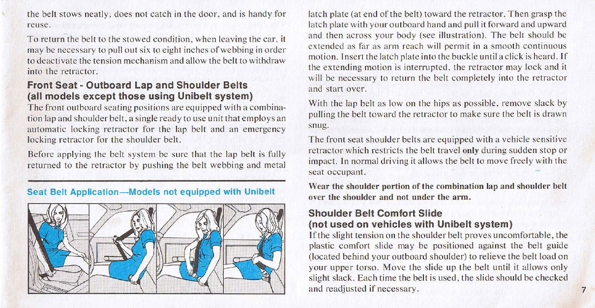
Seat
Belt
Application-Models
not
equipped
with
Unibelt
latch plate (at end
of
the belt) toward the retractor.
Then
grasp
the
latch
picHe
with
your
outboard
hand and pu
ll
it
forward and upward
and then
across
your body (see illustration).
The
be
lt
should be
extended
as far
as
arm reach will permit
in
a smooth
continuous
motion. Insert the latch plate into the buckle until a
cl
ick is heard.
If
the extending mot ion
is
interrupted. the
retractor
may lock and
it
w
ill
be
necessary to return the belt
complete
ly into the
retractor
and start over.
With the l
ap
be
lt
as low
on
the hips
as
poss
ib
le, remove sl
ack
by
pulling the belt towa
rd
the
retractor
to make sure the belt is drawn
s
nu
g.
The
front seat shoul
der
belts
are
equipped with a vehicle sensitive
retractor
which restricts the belt travel only during
sudden
stop
or
impact. In
norma
l driving
it
allows the belt to move freely with the
sea
t
occupant.
Wear the shoulder portion
of
the combination
la
p and shoulder belt
over the shoulder and not
under
the '}rrn.
Shoulder
Belt
Comfort
Slide
(not
used
on
vehicles
with
Unib
e
lt
syste
m)
If
the
slight tension on
the
shou
ld
er belt
proves
uncomfortable, the
plastic
comfort
slide may be positioned against
the
belt guide
(located behind
your
outboa
rd shoulder)
to
relieve the belt l
oad
on
your
upper
tor
so
.
Move
the sli
de
up
the
belt until it allows only
sl
ight slack.
Each
lime the belt is used ,
the
slide should
be
checked
and readjusted if
necessary.
7

8
AN
ADJUSTMENT
OF
THE
SLIDE
THAT
RESULTS
IN
MORE
SLACK
THAN
NECESSARY
TO
RELIEVE
THE
TENS
I
ON
MAY
REDUCE
THE
RESTRAINT
SYSTEM
EFFECTIVENESS.
To
Unfasten
and
Store
Belts
(except
on
vehicles
with
Uni
be
lt
system)
The
belts
arc
rel
eased
by
pushing
th
e button on the face
of
the
buckle.
Guide
the
belts
all the
way
back
into
thei
r r
etracto
r
s,
so
that
the
belt
stows
neally.
does
not
ca
t
ch
in
the
door
,
and
is
handy
for reuse.
On two
door
models the noor mounted
retractor
assembly
ca
n be
swiveled
toward
the
rea
r
of
the
ca
r
to
allow
eas
ier
en
tr
y
into
the
rear
seat.
However,
to permit the front seat
occupant
to r
each
the
belt
l
atc
h
plate
the
retractor
assembly
should
be
pushed
a
lilh
e
way
forward
once
the r
ear
scat
is
occupied.
Front
and
Rear
Lap
Belts
(all
models)
The
center
front
and
rear
seating
positions
arc
equipped
with
l
ap
belts
only.
(Rear
seat
shou
l
der
belts
are
avai
l
ab
le
at
your
dealer).
The
l
ap
belts
sh
ould
be
worn
with
the
upper
edge
of
the
belt
drawn
across
the
t
highs
and
snug
aga
inst
the
hips.
To
lengthen
the
belt.
tilt
the
l
atch
pl
ate
re
l
ative
to (
he
webbing
and
pull
to
the
desired
length.
To
reduce
the
risk
of
sliding
under
the belt in a
collision.
it
shou
ld
be
adjusted
as
tight
as
comfort
will
allow
WH
I
LE
SITTING
WELL
BACK
AND
ERECT
IN
THE
SEAT.
The
outboard
r
ear
sea
t
pos
iti
ons
(except
3rd
seat
on
stat
i
on
wagons)
are
equipped
with
automatic
locking
retracto
rs.
Withdraw
the belt
from
the
retractor
in a
co
nt
inuous
motion,
forward
and
upward
away
from
the
seat,
until
the
be
lt is
extended
as
far
as
possible.
Bling
the
belt
ac
ro
ss
the
body
and
insert
the
latch
plate
in
the
buck
le until a click is
heard.
Tighten
the
belt
by
pulling the
webbi
ng
back
toward.
and
into,
the
retractor
until
the
be
lt fits
snugly
on
the
hips.
Never lise the same lap belt on more
than
one person
at
a time.

Child
Restrain
t
When you are ca
rr
ying children in your
car
so
me
type
of
restraint
system should
be
us
ed
, regardless
of
the size
of
the child.
For
babies weighing up to 20
pounds.
ob
ta
in
a good in
fa
nt
carr
ier.
T he Chrysl
er
Safety Infant
Carrie
r (pa
ri
no. 3744975)
ca
n be
pur
cha
sed
from yo
ur
dealer.
This
method
of
carrying
a small child
is
recommen
de
d
if
the child is
unab
le to sit
up
by himsel
f.
The
chi
ld
is
sec
urely restrained faci ng
in
a rear
ward
di
r
ection
so that
in
the
event
ora
fo
rw
ard collision the child is
ade
quately supported.
For
c
hi
ldr
en weig
hi
ng l
ess
th
an
50 poun
ds
but
more
th
an
20 po
un
ds, we
recommend the purchase of a good Safety Seal. such as the
C
hr
ysler
Ch
ild
Sa
fely
Seal
(pa
rI
no. 3744976).
The
c
hi
ld
sea
l
assures
thai the l
oa
ds that might be
exerted
on
a child are dist
ri
·
buted
mor
e w
id
ely
over
the chil
d'
s body.
The
seat may be purch·
ased
from
your
dea
l
er
.
T he Child Scat
or
the Infant
Ca
rri
er
shou
ld
be belted inlo the
ce
nter seating
po
sition
of
the front or r
ear
seats.
This
provides the
greatest
prot
ectio
n in the
eve
nt your c
ar
is
struck
in
the side by
another
car.
Children weighing
ove
r 50
pound
s should
wear
the
sea
l belts
pro·
vided in the
ca
r.
The
c
hil
d should be se
ated
upright in
the
sea
t
wi
th
the l
ap
belt fastened low on the
hi
ps and as snug as p
ossib
le. A child
wear
ing a l
ap
be
lt
ca
n be el
evated
to sec out
of
th
e
car
if the
el
evat
in
g platform is rigid
and
unyie
ld
ing and light in weight
(styrofoam is good).
To
ins
ur
e
adequate
protectio
n
in
a side im·
pa
ct.
we suggest that
the
pla
tf
orm
height not
exceed
thr
ee
in
ches
.
and
th
at
it
should be
as
wide
as
the di
stance
between
the
be
lt
s used
to secure the seal. Children sh
ou
ld
be
sea
ted in a rear
sea
t
or
in the
center
front seat. If it is essential f
or
the c
hi
ld to sit in the right front
seat. and the shoulder belt lies
across
th
e
fa
ce
or neck
or
the child so
as 10
cause
di
sco
mf
ort.
extend the sho
ul
der
belt
webbing
out from
the re
tr
actor
and
position the comfort slide along
the
webb
ing
as
descr
ibed
ear
lier to
keep
the
webb
ing from
retrac
ting. A slight
amount
of
additi
ona
l sl
ack
will a
ll
Q\.\'
the
shou
l
der
be
lt
webb
ing to
fa
ll
away
fr
on
the chi
ld'
s neck or
I
~
l
ce.
9

Instruments and Controls -Gran Fury
I.
Headlight
Switch
2. Windshield Washer/Wiper
3. Re
ar
Window
(Doo
r-
gale)
4. Cl
ock
or
Gauge
Package
5. Cooling Ou
tl
ets
6. Doorgate Lock
7.
Radio-Tape Player
10
8. H
eater-A
ir
Cond
itioner
9.
Map
Light
Switch
10.
G l
ove
C
ompartment
'
11
. Remote
Mirror
(right s
id
e)
12.
Ash
Tra)
1
13. Lighter
14. R
ear
Defroster
15
.
Brake
Release
CLUSTER ASSEMBLY -GRAN FURY
A.
Fuel
Gauge
With ignilion
key
in
"On"
pos
it
ion. the
pointer
wi
ll
indicate
the
level of fuel
in
ga
soline tank.
Optional
Low Fuel
Indicator
- A small light in
the
upper
corner
will signal
when the
fucllcvel
is
bel
ow
approx
im
ately
\.1i
full.
When
the fuel
tank
is
ncar
this
le
vel
it
is
normal
for the
li
ght
to
nicker an
er
fast
SlOps.
while
turnin
g
co
rn
ers
or
while driving
on
hilly terrain.

B. Oil
Pressure
Light
'"
A red
lig
ht ind i
ca
t
es
engine
oi
l
pr
essure is below
normal. It may
be
on momentarily whcn the engine is first started or is
operating at
id
l
e.
If
Ih
e light sla
ys
on w
hil
e dri
vin
g, slop the eng
in
e im·
med
ia
tely and do not operate
car
unt
il
cau
se
is
co
rr
ected.
Li
ght does not
indicHte amount of oil in the crankcase.
C.
Turn
Signal
Indicators
Li
ghts
n::t
sh
in
unison with eXlerior li£hts when
signal
le
ver is operated.
D.
Gate
Aj
ar
Warning
light
(Station
Wagon)
On stat.ion wagons the
"Gate
Aj
a
r"
i
ndi
ca
tor wi
ll li
ght i
fl
he d
oo
r
ga
te is
110
t com pletely closed.
D.
Door
AjarW
a
rning
Light
(op
tion
al
a
ll
models)
Indicat
es
a side door
is
not completelyclosed.
On
station wagonsequipped wilhIhe
Op
tional
Li
ght
Package. the .,
Door
Ajar
" indicat
or
wi
ll
li
ghl
ifa
nyof the side doors or the
d
oo
rgatc is not closed.
Note :To
de
termine ir
"Ga
te Ajar" or
"Ooo
r Ajar" indicators are function·
iug sutisfactori
ly
, it is r
eco
mmended that each d
oo
r and doorgate be open
ed
individua
ll
y with the
ig
nition s
wi
tch
in
lhe "On" position.
Cluster
Details
-Gran Fury
1
o E H
10
90
r---, r-- •
'
E
i~~
~'I~
F
~~
~p
~
:
,
]
o
I
:
o
~
\
~
~
~
~
O
.;
ASO
I
NE
\
2)
\\~NA
T
OR
B A L
:-<:
J
E.
Fasten
Seat
Belt
Light Fo
rd
el
<lils
of the function and opera
ti
on
of
this
light
se
e page 3.
F. High
Beam
Indicator
A blue light signals that yo ur headlights are on
hi
gh beam.
G.
Brake
System
W
ar
ni
ng
Light
Thc
opera
tion ofthis
li
ght is explained in
detail on page 22.
H. Wi
ndshield
W
as
her
Fluid Leve l I
ndicator
Optional with 3-Spccd
Wiper - Whe n the w
as
her control is depressed a red
li
ght in
di
cat
es
that the
washer reservoir is below
~
fill
ed
.
I.
Cool
a
nt
Temper
a
tu
re
Light* When the light glows red it i
ndi
ca
tes the
engine coolant is overheated. T he
car
shou
ld
be parked, the en
gi
ne turned
0
1T
and not oper
ate
d until the
ca
use is c
or
rected.
The
red light com
es
on
momentar
il
y when engine is started. indicating
it
is function
in
g prope
rl
y.
J. Alte
rnator
Indi
cat
or
Indicales wheth
er
battery
is
be
in
g char
ge
d
("C
')
or
di
scharged C' 0 " ). P
oi
nler
wi
ll
nomm
l1
y stay ncar
ce
nt
er
if
ba{\
cry is
full
y charged.
Optional Low Baltery
Vo
lt
age Indicator - A sma
ll li
g
ht
in the upper co
rn
er
w
ill
signal that
th
e elec
tr
ic
al system should be ch
ec
ked. If the light ext
ing
-
uis
he
s
wi
th in
creas
ed eng
in
e speed,
or
reduced accessory load, y
our
bat·
lery is accepting a charge. If the
li
ght rema
in
s on and the alt
er
n
<l
tor indi·
ca
tor sh
ows
charge,
it
is an indication or a raulty battery w
hi
ch is n
ot
acce
pting a charge and should be immediately checked.
K, EGR
Ch
eck
Li
gh
t (If so e
quipp
ed) This l
ig
ht is d
es
igned to come on
at
15.000 mile
in
terv
al
s to remind you to pelforrn the EGR system m
ai
nte-
nan
ce
.
L.
Od
om
ete
r Indi
ca
t
es
to
tal
mil
eagc the
car
has been dri
ve
n.
*A temp
er
alur
e a
nd
o
il
pr
essure gauge assembly is available as optional
cquipmc
nL
If
o
rd
ered.
Ihi
s assembly is mounted in the opening provided
for the cloc
k.
11

Instruments and Controls -Fury
1. Headlight Switch
2. WiperfWasher
Co
ntrol
3. Map Light (optional)
4. Air Conditioner O
utl
ets
(o
pti
ona
l)
4A. Upper Level Ventilation
Outlets
12
(optiona
l)
5. Heated Rear Window (optional)
6. Doorgate Window lift a
nd
/or
Auto
Lock (station wagon
op
tion)
7. Heater and/or
Ale
Co
ntr
ols
8. Fr
esh
Air
Vent
Co
ntrol (not on cars
with AIC)
9. Radio (optional)
10. Ash T r
ay
a
nd
Lighter
11
. Glove
Box
L
ock
an
d
Re
l
ease

CLUSTER
DETAILS
-FURY
Note:
If
tachometer
or
clock option
is
selected, the Oil
Pressure
Gauge
and
Fu
el
Gauge will
be
grouped in location
"0"
and
the
Te
mperature
and
Alternator
Gauges in location
"E"
.
A.
High·Beam
Indi
c
ator
A blue light indicates 'when
yo
ur head-
li
ghts are on high b
ea
m.
B.
Turn
Signal
Indicators
Lights nash in uni
so
n
wi
th outside
lights when signal is operated.
C.
Temperature
Gauge
Indi
cates engi
ne
coola
nt
tempera
tur
e.
If
the
poinl
er rises su
ddenly
(except when restarting
after
a short
stop)
or
remains on " H
",
stop
ca
r, turn
off
engine and do n
ot
operate car until cause is located and
cor
rected.
Cluster
Details
-
Fury
A B c D E
F G H K
D.
Oil
Pressure
Light
A red light indicates the engine oil pressure
is bel
ow
n
orma
l.
It
may be on momentarily when the eng
in
e is first
started, or is operating at
idl
e.
lfth
e light stays on while driving, stop
the engine immediately and do not operate
car
until the cause
is
corr
ected. T he light
do
es
not indi
cate
amo
unt
of
oil
in
the crank-
case
. This
ca
n be determined by check
in
g the o
il
di
p
st
ick.
E.
Alternator
Indi
c
ator
Indicat
es
battery is being char
ged
('"C·)
or di
sc
harged
(",D··)
.
F.
Speedomete
r Indicates speed
in
MPH
and Kilometres
Per
HO
UI".
G.
Odometer
Indi
cates
t
ota
l m
il
eage the car has been driven.
H.
Fuel
Gauge
With the ignition
in
the
"On"
position the gauge
will indicate level
of
gaso
lin
e in fuel tank.
(Optional Low Fucl Indicator) - A sm
al
llight
in
the face
of
the gauge
w
ill
signal when the fuel level is below approximately !4 full. When
the
fu
el tank is n
ear
this levelit is normal
fo
rthe
li
ght to
fli
cker after
fast stops, while turning
co
rn
ers or wh
il
e d
ri
ving on hill y terra
in
.
I.
Fasten
Seat
Be
lt Light
Fo
r
deta
ils
of
the function and operation
of
this light
see
page
3.
J.
Brake
System
Warning
Light
The
opera
ti
on of t
hi
s
li
ght is
explained
in
detail on page 22.
K. EGR
Check
Light
(If
so
equipped)
This light is design
ed
to
come on at 15.000
mi
le intervals to reniind you to pelform the
EG
R
systcm maintenancc. 13

Instruments and Controls -Volare
1.
Air
Conditioner
Outlets
(optional) 7.
Map
Light
(if
so
equipped)
13
. Wi
per
Washer
Co
ntrol
2.
Clock
(optional) 8. Ash
Tray
and Li
ghter
14
. Fu
se
Access Door
3.
Instrument
C luster 9. Remote
Control
Mirror
Right Side (optional)
15
. Brake Release
4.
Heater
and/or
Air
Co
ndo
Controls
10.
Radio (optional)
16.
Head
light
Switch
5. G l
ove
Co
mpartment
11.
Inside
Hood
Rel
ease
(if
so
equipped)
14
6.
Vent
Control (not
on
Ale
equipped
cars)
12.
Rear
Window
Defroster
(optional)

CLUSTER DETAILS -
VOLARE
A.
Temperature
Gauge
Indicates engine coolant tempera
tu
re. If
the pointer
ri
ses
suddenly (except when restarting arter a short
stop)
or
remains on " H'·.
SlOp
car. turn
off
engine and do not
operate car unt
il
cause
is
located and corrected.
B. Tu
rn
Sign
al
Indica
t
ors
Lights on ins
tr
ument panel flash in
unison with
exterior
lights when turn signal is operated.
C.
Hig
h
Beam
I
nd
i
ca
tor A bl
ue
light signalswhen your headlig
ht
s
are on high beam.
Cluster
Details
-
Volare
D.
Fue
l
Gauge
With ignition key in the
"On"
position. the
po
inter
wi
ll
indicate
th
e level
of
fuel
in
gaso
li
ne
tank.
E: EGR
Check
Ligh
t (
If
so
equipped)
Th
is light is designed to
come
on
at 15,000 mile
in
terva
ls
(0
rem
ind
you
to
perform
the
EG
R
syst
em
maintenance.
F. Oil Pr
essu
re Light A red
li
ght indi
cates
en
gi
ne oil
pressure
is
below norma
l.
It
may be on momentarily when the engine
is
fi
r
st
started or
is
operati
ng
at
id
le.
If
the light stays on w
hi
le
driving, stop
the engine immediately and
do
not operate car until cause is cor-
rected. Light
does
not indicate amount
of
oil in the
crankcase.
This
can
be determined by checking the oil level dip stick.
G.
Bra
ke
System
Wa rning Light See page
22
for function
of
this
light.
H. Odomete r Indi
cates
total
mi
leage the
car
has been
dr
iven.
I.
Alterna
tor
Ga
uge
Indicates
whether
battery
is
being charged
("C
" )
or
discharged
("'
0").
Pointer will normally stay near
center
while driving if battery is fully charged.
J .
Fasten
Seat
Belt
Light
Fordetail
s
of
the function
and
operation
of
this light s
ee
page
3.
15

Instruments and Controls -Valiant
1. Head
li
g
ht
s.
Do
me a
nd
Panel
Li
ghts
2. Winds
hi
eld Wiper a
nd
W
as
her
Co
ntrols
3.
Fa
n Sw
it
ch
4. Heater or
op
ti
o
na
l
Ai
r Conditioner
16
Co
ntrols
,
5. Par
ki
ng
Brake
Re
l
ease
6. Map Light Switch (optional)
7. Check
EGR
Light
(If
so equipped)
8. RearWi
nd
ow
De
froster (optional)
9. Fasten Scat Bells
Li
g
ht
10. Hood Release (optional)
11. Rear Speaker Co
nt
ro
l (o
pt
ional)
12
. Ash T ray and Lighter
13
. Radio Controls (optional)

CLUSTER DETAILS -
VALIANT
A.
Alternator
Gauge
Indi
ca
t
es
whether
baltcry
is being char
ged
("C")
or
di
sc
har
ge
d
C'
D
O').
Po
inl
cr w
ill
normally st
ay
nearcenter
wh
il
e
dr
iving
if
battery
is fully charged.
B.
Temperature
Gauge
Indicates engine coolant
temp
erature.
If
the
pointer
ri
ses
sudde
nl
y
(excep
t
when
resta
rting a
flcr
a sh
or
t
SlOp)
or r
ema
in
s
near
250.
SLOp
the
c
ar.
turn
off
engine
and
do
not
ope
r
ate
car
until
ca
u
se
is lo
cated.
C. Fuel
Gauge
With
ignition key in the
"On"
position, the point
er
will
indicate the level
offuel
in gasoline tank.
D.
High
Beam
Indicator
A blue light signals when your headligh
ts
are
on
high b
ea
m.
Cluster
Details
-
Valiant
K J H G
E. Oil
Pressure
Light
A red light indi
cates
engine oil pre
ss
ure
is
be
l
ow
normal. II may be on
mom
entarily when
the
engine
is first
sta
rted o r is operating at idle.
If
th
e light stayson while
dr
i"ing, stop
the engine immediately
and
do not ope
rat
e car until cause is
cor~
reeled. Light
does
11
0t
indi
ca
te
amoun
t oroil
in
the
cr
ank
case.
T
hi
s
ca
n
be
determined
by ch
eck
in
g the oil l
eve
l dip stick.
F.
Brake
System
Warning
Light
See
page
22
for func
ti
on
of
this
light.
G.
Speedometer
Indi
ca
tes
car
sp
eed
in miles
per
hour.
H.
Turn
Signal
Indicators
Lights on
in
s
trumen
t panel
fl
as
h
in
unison with
exte
ri
or
li
ghts wh
en
turn
sig
nal is
operated.
I.
Odometer
Ind
icates
total mil
eage
th
e
ca
r has
driven.
J.
Fasten
Seat
Belt
Light
Fordetail
so
fthe
func
ti
on
and
operaiion
of
Ihi
s lighl
see
page
3.
K. EGR
Check
Light
(If
so
equipped)
Th
is lighl is design
ed
10
co
me
on
at
15
.000 mile intervals
to
remind
you
to
perform
the
EG
R
syste
m mai
nten
ance.

18
Operation
Glove
Compartment
To
open the glove com
pa
rtment rotate the latch in a cl
ockwi
se
di
rection.
Use
k
ey
with
r
ound
end
to
l
ock
compartment.
Luggage
Compartment
To
unlock, u
se
key
with
round end.
Turn
key to the right
an
d the
co
unt
erba
l
ance
d
tr
unk lid wi
ll
rai
se
easi
ly.
The
li
d will l
ock
when
closed, whether
or
not the key is
in
the lock.
Roof
Type
Carrier
Warning
Do not lISC a
roof
type
carrier
that
rests on
or
clamps
to the
drip
mO
lding.
If
loads
arc
app
li
ed
to
the
drip
molding the molding will
deform allowing the
rack
or
carrier
to
break
loose when the
car
is
underway.
Ash
Tray
and
Lighter
An
asht
ra
y and light
er
(optional on some
Valiant
models) are
l
ocate
d
in
the
ce
nter
of
the
in
str
ument
pan
e
l.
Caution
It
is
rct.
:
ommcn
dcd
that
011
1.\ th
t.'
li
g
ht
er
be insl'
rl
cd
in
the
rl
'cl'ph.u:k .
Usc of
"plu
g-in"
1
~p
('
an'
('
s~o
r
j('~
(
sp
otlig
ht-;
sha \
l'r
s, l'h
',)
nm
,'
d
~
II11
M
<lgl
'
th
e rcct'
ptadc
and
rt'.';ult in pnor
rd
t
ll
tioll
of
th
l'
li
gh
tl.!r,
Park
ing
Brake
When
the ignition swit
ch
is
in
the
'·O
n"
position
a
red
li
ght in
the
in
strume
nt
cluste
r
indicate
s
when
the
Parking
brake
is
app
lied.
Be s
ur
e
the
parking
bra
ke is
lirmly
set
whe
n
parked
and
th
e
gea
r-
shift
lev
er is in
Pa
rk posi
ti
on.
When
parking
on
a hill
you
s
hou
ld
app
ly
the
Parking
Br
ake
before
pl
acing
the
gea
r
sh
ift l
eve
r
in
"Park",
Thi
s
pr
even
ts
lo
adi
ng
the
parking
brake
pawl
again
st the
tr
ansm
i
ss
ion
ge
ar.
Wh
en
this
happen
s, it is
dilf
icult
to
m
ove
the
gear
sel
ecto
r out of
the
Park
position,
As
an
added
precaution
,
when
parking
on
a
dow
nh illgr
ade,
turn
the rront
wheels
Imvard
the
cur
b,
away
from the
curb
on
uphi
ll
gr
ade.
Caution
C
hi
l
dr
cn left unattended in a
car
should be
na
rn
ed not to touch the
park
ing
brakc
.'
c1c
a
.'Jc
Inc
r
or
the gea.' selector lever.
Pa
rkin
g Brake

AUTOMATIC TRANSMISSION
Column
Mounted
Selector
The
sel
ec
tor
l
ever
i
~
mounted on the right si
de
of
the steering
co
lumn
.
To
drive
,
move
the
selec
t
or
le ver
from
Park
or
Neutra
l
to
the
de
sir
ed
drive
po
siti
on.
Pull
se
l
ector
l
ever
toward
you
when
shifting into
Rever
se
.
Second,
First
or
Park
, or
when
shifting
ou
t
of
Park.
Cons
ole
Mounted
Selector
The
se
l
ec
tor,
on
the
conso
le
pane
l l
ocate
d at
the
driver's
right. is
illumin
alcd
for
ni
ght driving.
The
selector l
ever
may
be
shifted
fr
eely
from
Neut
ral to
Drive.
To
move
the
[
eve
r
to
or from
Park
po
si
ti
on
to
Second, First. or Reverse.
il
is necessary to depress the
shift
lever
button
, l
oeaied
on the
se
l
ector
l
eve
r.
Note
: A console
mounted
shift lever can be moved
out
of
park
after
the
ignition key
has
been renuI\:cd.
Therefore,
it
is
vcr}'
important
that
chil
dren
len
in
the
car be
ca
utioned
ag~linst
touching
the
shift
lever.
Also, the
parking
brake
should be fully
applied
before
leaving
the
car
on
an
incline.
Qu
i
ck
Sh
ift
Mechanism
(Fury)
-
Conso
le
mount
ed shift
co
ntr
ols
incor
po
r
ate
a
quick
shift feat ure.
The
q
ui
ck shi
ft
will faci
li
tate fast
accurate
manual
opera
tion
orlhe
transmi
ss
ion
and
prevent
mi
ss
ed
shifts. Shifting
th
e l
ever
to
First
activates
the
spee
d-shift
gate.
Then
when
you
move
the l
eve
r to
Second,
a
gate
s
tops
the shift
leve
r
from
moving
thru
this range.
Mov
ing the l
eve
r
forwa
rd
again
after
a
pause
will
engage
Dr
i
ve.
where
another
gate
stops
it
from
shifting
through
Neutral.
O n
ce
the
gate
sys
t
em
is in
operat
i
on.
the
bulton
on
the
shift l
ever
knob
mu
st
be
pus
hed
to
shift
to
Ne
utr
al.
If
the
gate
sys
t
em
is not
activat
ed
. shifts
can
be
made
from
Neutra
l
to
Drive
and
bac
k
to
Ne
u
tra
l
without
push
ing the
button.
AI
no
time
ca
n
Reverse
of
Park
be
engaged
without
first
pushing
the
button.
GEAR RANGES
DO
NOT
race
the engine
when
Sh
ifting
from
Park
or
Neutral
posi-
tions i
nto
another
gear
range
.
"P"
Park
Supp
l
ements
pa
rking
br
ake
by
l
ock
ing the
tr
ansmi
ss
ion.
Eng
in
e
can
be
sta
rted
in this
ran
ge.
Never
u
se
Park
while
ca
r is
in
motion.
Apply
parking
brake
when
leaving
car
in
this
range.
OR"
Reverse
Sh
ift
into
this range o
nl
y
afte
r the
ca
r
has
co
rn
e
to
a
complete
s
top.
"N"
Neutral
Eng
in
e
may
be start
cd
in
this range.
"0"
Drive
Fo
r most city
and
highway
dr
iv
in
g.
"
2"
Second
Fo
r driving slowly
in
heavy
city traffic
oron
mountain
road
s
where
more
prec
i
se
s
peed
co
ntrol is
desirable.
Usc
it al
so
whe
n Cli
mbing
long
grades.
and for
"engi
ne
braking
"
whe
n
desce
n
ding
moder-
ately
stee
p grad
es.
To
prevent
('xnssh'e
engine
speed
do not exceed
60 mile
per
hour
in Second.
19
This manual suits for next models
3
Table of contents
Other Plymouth Automobile manuals

Plymouth
Plymouth Cranbrook User manual

Plymouth
Plymouth Valiant 1968 User manual

Plymouth
Plymouth Pl4S User manual

Plymouth
Plymouth Valiant 200 1969 User manual

Plymouth
Plymouth Plaza 1957 User manual

Plymouth
Plymouth Valiant V-100 1965 User manual

Plymouth
Plymouth SAVOY 1961 Operating manual

Plymouth
Plymouth Fury 1369 User manual

Plymouth
Plymouth Plaza 1955 User manual

Plymouth
Plymouth Gran Fury 1980 User manual