0-2
LUBRICATION
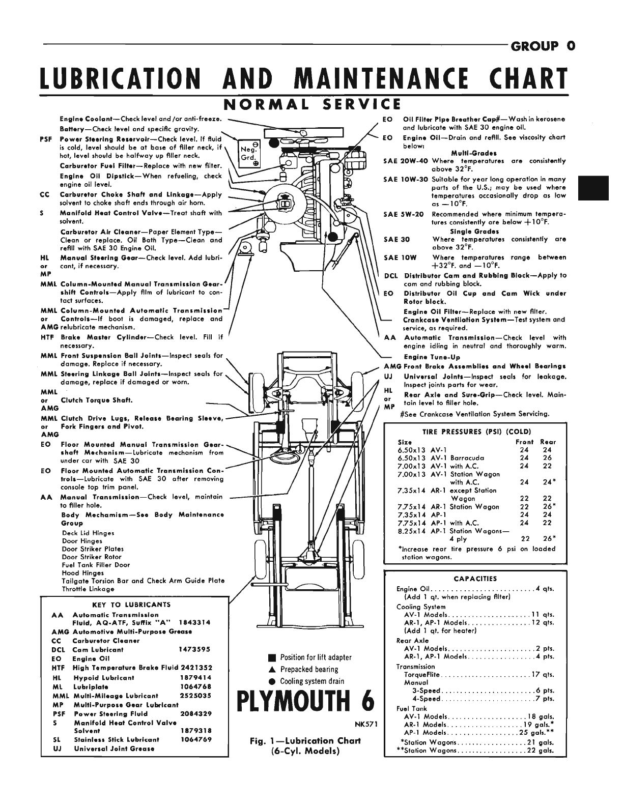
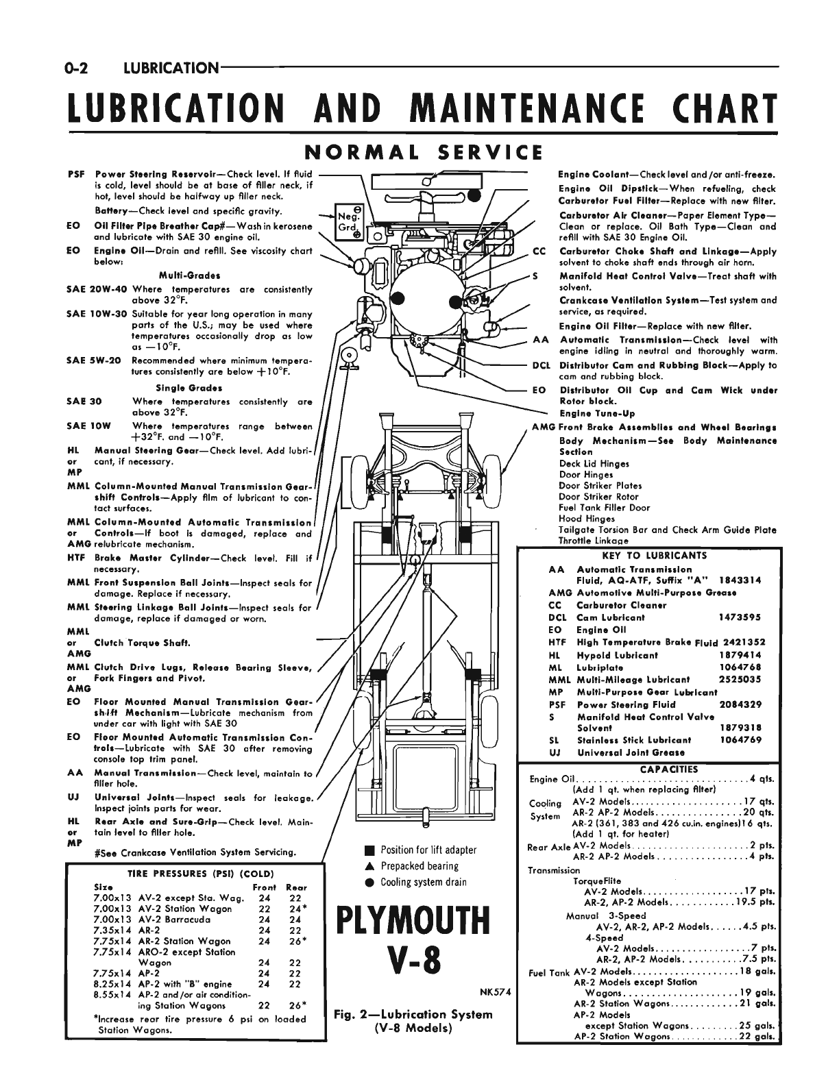
LUBRICATION AND MAINTENANCE CHART
NORMAL SERVICE
PSF Power Steering Reservoir-Check level.
If
fluid
is
cold, level should be at base of filler neck, if
hot, level should be halfway up flller neck.
Battery-Check level and specific gravity.
Oil
Filter
PipeBreatherCap#- Washinkerosene
and lubricate with SAE 30 engine oil.
below:
EngineCoolant-Check level and/or anti-freeze.
Engine
Oil
Dlpstlck-When refueling, check
Corburetor Fuel Filter-Replace with new filter.
Carburetor Air Cleaner-Paper ElementType-
EO Clean or replace. Oil Bath Type-Clean and
refill with SAE 30 Engine Oil.
EO
Engine Oil-Drain and refill. See viscosity chart CC Carburetor Choke Shaft and Linkage-Apply
solvent to choke shaft ends through air horn.
MultiOrades
S
Manifold Heat Control Valve-Treat shaft with
SAE 2OW-40 Where temperatures are consistently solvent.
above 32'F. Crankcase Ventilatlon System-Test system and
SAE 1OW-30 Suitablefor year long operation in many service, as required.
parts of the
US.;
may be used where Engine
Oil
Filter-Replace with new fllter.
temperatures occasionally drop as low AA Automatic Transmission-Check level with
engine idling in neutral and thoroughly warm.
as -1OOF.
DCL Distributor Cam and Rubbing Block-Apply to
Recommended where minimum tempera- cam and rubbing block.
tures consistently are below +1
O'F.
Single Grades EO Distributor Oil Cup and Cam Wlck under
SAE 5W-20
SAE
30 Where temperatures consistently are Rotor block.
SAE 1OW Where temperatures range between
G
Front Brake Assemblies and Wheel Bearlngs
Body Mechanism-See Body Maintenance
HL
Manual Steering Gear-Check level. Add lubri- Section
or cant,
if
necessary.
MP
MML
Column-Mounted ManualTransmissionGear-
shift Controls-Apply
film
of lubricant to con-
tact surfaces.
above 32'F. Engine Tune-up
+32OF. and -1 0°F.
MML
Column-Mounted Automatic Transmlsslenl
/
/I
2
or
Controls-If boot
is
damaged, replace and
AMGrelubricate mechanism.
necessary.
damage. Replace
if
necessary.
MML
Front Suspension BallJoints-Inspect seals for
HTF Brake Master Cylinder-Check level.
Fill
if
I//
l,T/$'f
7
MML
Steering Linkage Boll Joints-Inspect seals for
MML
or
Clutch Torque Shaft.
AMO
MML
Clutch Drive Lugs, Release Bearing Sleeve,
or
Fork Fingers and Pivot.
AMG
EO Floor Mounted Manual Transmission
Gear-
shMt Mechanism-Lubricate mechanism from
under car with light with SAE 30
Floor Mounted Automatic Transmission Con-
holr-Lubricate with SAE
30
after removing
console toD trim aanel.
damage, replace
if
damaged or worn.
EO
AA ManualTransmlrsion-Check level, maintain to
filler hole.
UJ
HL
or
Universal Joints-Inspect seals for leokage.
/
Inspect joints parts for wear.
Rear Axle and SureQrip-Check level. Main-
tain level to flller hole.
I\
ll
/
Positionfor liftadapter
MI
#See
Crankcase Ventilation System Servicing.
I
A
Prepackedbearing
0
Coolingsystem drain
TIRE
PRESSURES (PSI) (COLD)
Size Front Rear
1
7.00~13AV-2 exceDt Sta. woo. 24 22
1
7.00~13AV-2 Station Wagon
-
7.00~13AV-2 Barracuda
7.75~14AR-2 Station Wagon
7.75~14ARO-2 except Station
7.35~14AR-2
Wagon
775x14 AP-2
8.25~14AP-2 with
"B"
engine
8.55~14AP-2 and/or air condition-
ing Stotion Wagons
22 24%
24 24
24 22
24 26%
24 22
24 22
24 22
22 26*
*Increase rear tire pressure
6
psi on loaded
Station Waaons.
PLYMOUTH
I
V=8
NK574
Fig. 2-lubrication System
(V-8
Models)
Deck Lid Hinges
Door Hinges
Door Striker Plates
Door Striker Rotor
Fuel Tank Filler Door
Hood Hinges
Tailaate Torsion Bar and Check Arm Guide Plate
Throile Linkage
KEY TO LUBRICANTS
AA Automatic Transmission
AMG Automotive Multi-Purpose
Ormse
CC Carburetor Cleaner
DCL Corn Lubricant 1473595
EO Engine Oil
HTF High Temperoture Brake Fluid 2421352
HL
Hypold Lubricant 1879414
ML
Lubtipiate 1064768
MML
Multi-Mileage lubricant 2525035
MP Multi-Purpose
Gear
Lubricant
PSF Power Steering Fluid 2084329
S
Manifold
Heat
Control Valve
Solvent 1879318
SL
Stoiniess Stick Lubrlcant 1064769
UJ Universal Joint
Grease
Fluid, AQ-ATF, Suffix "A" 1843314
CAPACITIES
Engine Oil.
..............................
.4qts.
Cooling AV-2 Models..
..................
.17 qtr.
system AR-2 AP-2 Models..
.............
.2O qts
Reor AxleAV-2 Models.
....................
.2 pt%
AR-2 AP-2 Models.
...............
.4 ph.
AV-2 Models..
................
.I7
pth
AR-2, AP-2
model^.
..........
.19.5 pts.
AV-2, AR-2, AP-2 Models.
....
.4.5 ptS
AV-2 Models..
...............
.7
pts
AR-2, AP-2 Models.
.........
.7.5 pts
Fuel Tank AV-2 Models..
.................
.18
gals,
Wagons..
..................
.19
gob,
AR-2 Stotion Wagons..
..........
.21
gals,
(Add 1 qt. when replacing fllter)
AR-2 (361,383 and 426 cu.in. engines)l6 qts.
(Add
1
qt. for heater)
Transmission
TorqueFlite
Manual 3-Speed
4-Speed
AR-2 Models except Station
AP-2 Models
except Station Wogons.
.......
.25 gals.
AP-2 Station Wagons.
...........
.22 gath