Plymouth Plaza 1955 User manual


MyMopar.com

PLYMOUTHSERVICEMANUAL
1956
PLY
1955
OU T H
P-26,P-27
56P128
MyMopar.com

PLYMOUTHSERVICEMANUAL
Senvic¢... ô«men,
Customerconfidencepaysdividendsover
the
years.Treating
a
customer's
carasyouwouldyour
own
makes
an
ownerfeelthat
youare
rendering
a
service,
not
simplyselling
a
repair
job.
There's
a
greatdifferencebetween
anhonestdesire
tobeof
friendlyservice
toa
customerand
a
desire
to
simplysell
a jobof
service!
A
customerquicklyrecognizes
the
service
man
whotakes
a
personalinterest
inhis
welfare,
and
gets
a
feeling
of
confi-
dence
and
satisfactionthatmakes"habit"customers
outof
"now¯and¯
then"
customers.
Experience
has
shownthat
oneofthe
bestways
to
createcustomer
confidence
isto
offersafetyinspections
and
roadtests
asa
part
of
your
service
to
themotorists
in
yourcommunity.Likeothersuccessfulservicemen,
youwillfindthatmotoristsappreciateratherthanresenthavingyourrecom-
mendationsaboutwhatshould
be
done
to
maintainsafevehicleoperation.
Thereareoverfifty-fourmillionautomotivevehiclesinop-
eration
inthe
UnitedStates.Everyyear
asnew
vehicles
areput
into
use,
new
inexperienceddriverstake
the
wheel,increasing
the
problem
of
handlingtraffic
onour
streets
and
highways.Theremust
be
greatereffort
on
the
part
of
everyoneconcerned
to
helpkeepthesecars
in
safeoperating
condition.
Much
ofthe
responsibilityfalls
onthe
shoulders
of
service
men.
Servicemenhavetheresponsibilityofkeepingmotorists
informedabouttheoverallconditionoftheirvehicles—par-
ticularlythoseunitsuponwhichthedriverdependsforsafe
operation.
Servicemenhavetheresponsibilityofeducatingdrivers
aboutthehazardsofdrivinganunsafevehicle.
Servicemenhavetheresponsibilityofadvisingdriversabout
theneedforperiodicalsafety-inspections.
Servicemenhavetheresponsibilityofkeepingdriversin-
formedabouttheneedforperiodicalsafetymaintenance.
Servicemenwhoaccepttheseresponsibilitiesandtreateach
customer'scarasthoughitwerehisown,willreapthebenefits
ofcustomerconfidenceandsatisfaction.
MyMopar.com

PLYMOUTHSERVICEMANUAL
Model
P-26Plaza,Savoy,Belvedere
P-27Plaza,Savoy,Belvedere
P-28Plaza,Savoy,Belvedere
P-29Plaza,Savoy,Belvedere
StartingVehicleNumbers
Detroit
13,835,001
15,663,001
14,120,001
15,873,001
Evansville
20,745,001
22,182,001
20,820,001
22,247,001
LosAngeles
25,180,001
26,524,001
25,202,001
26,552,001
VEHICLENUMBERLOCATION
The vehicle number (serial number)
is
located
on a
plate which
is
attached
to
the
left front door hinge pillar post
ENGINENUMBERLOCATION
The engine number
is
stamped
on a
boss
on the
left side
at the
front
of the
cylinder block
on the
PowerFlow
6
engines.
On
157, 167,
and
180 horsepower
Hy-Fire V-8 engines,
the
number
is
located
on top of the
engine
at the
front,
next
to the oil
filler pipe.
On
187
and
200 horsepower Hy-Fire
V-8
engines,
the
number
is
located
on the
left front face
of the
cylinder block.
BODYNUMBERLOCATION
The body number
is
stamped
on a
plate which
is
attached
to the
left side of
the engine side
of the
dash.
Vote ¢utd
Sþec¿ftcœUo*¢>
Model
Number
oí
Cylinders
Bore
&
Stroke
PistonDisplacement
CompressionRatio
AAaximum
BrakeHorsepower
TaxableHorsepower
MaximumTorque
Wheelbase
Tread—Front
Tread—Rear
OverallLength
OveraUWidth
TurningDiameter
P¯26P-28
6
3½
x 4¾in.
230
cu.in.
7.4
to1
117
at
3600
RPM
25.4
194at1600
7.6
to1
131
at
3600RPM
25.4
2OOatl6OO
P-27
V-8
3%x3½in.
241cu.in.
7.6to1
157at
4400
RPM
37.9
217at
2400
3%x3½in.
260
cu.in.
7.6to1
167
at
4400
RPM
40.6
231at
2400
P-29
V-8
3¾x3¼in.
270
cu.in.
8.0to1
180at
4400
RPM
42.2
260at
2400
3¾x3½in.
277
cu.in.
8.0
to1
187
at
4400RPM
45
265at
2400
115
in.
58.4
in.
58.5
in.
203.8
in.
204.8
in.
203.8
in.
204.8
in.
74.6
in.
40
ft.1 in.40.6ft.
MyMopar.com

PLYMOUTHSERVICEMANUAL
ThisPlymouthServiceManualhasbeenpreparedasa referencebook
ofcompleteserviceinformationforthePlymouthmodelsillustratedon
Page2.
Forconvenience,thecontentsofthemanualhavebeenarrangedbysec-
tions.
Eachsectioncontainschartsofdataandspecifications,adjustments
andrepairinformation,anddiagnosisprocedures.A listofthesubjectscov-
eredineachsectionwillbefoundatthebeginningofthesection.A complete
alphabeticalindexappearsinthebackofthemanual.
TohelpdiagnosetheserviceneedsofthePlymouthcar,thismanualcon-
tainsover200diagnosisprocedures.Inmostinstancesitisadvisableto
makea roadtesttoverifytheconditiondescribedbythecustomersothat
thecorrectionsgiveninthediagnosisprocedurescanbeapplied.
Throughoutthemanual,servicedataandspecificationsaregiveninchart
form.
Theclearancesandspecificationsshownarebasedonthetypeof
equipmentnormallyavailableforserviceworkanddonotinallcases
representthemanufacturingspecifications.
Thismanualcontainsserviceinformationforunitsoriginallyinstalledon
Plymouthcarsas"specialequipment."Noattempthasbeenmadetodesig-
natesuchunitsas"specialequipment"inthismanual.
CHRYSLERCORPORATION
PlymouthDivision
ServiceDepartment
Detroit,Michigan
MyMopar.com

PLYMOUTHSERVICEMANUAL
NUT
SUSHtNG
AND
SPACER
WASHER
BOLT
BAR
SEAL
LOCK
SEAL
SCREW
BUSHING
BUSHING
5SPÌO58
Figure1 — FrontSuspensionParts
MyMopar.com

SECTIONI
FRONTSUSPENSIONSYSTEM
Page
DataandSpecifications8
1.
FrontWheelAlignment7
2.
FactorsofFrontWheelAlignment7
3.FrontWheelAlignmentCorrections10
4.TieRodEnds12
5.SteeringKnuckleandSupport12
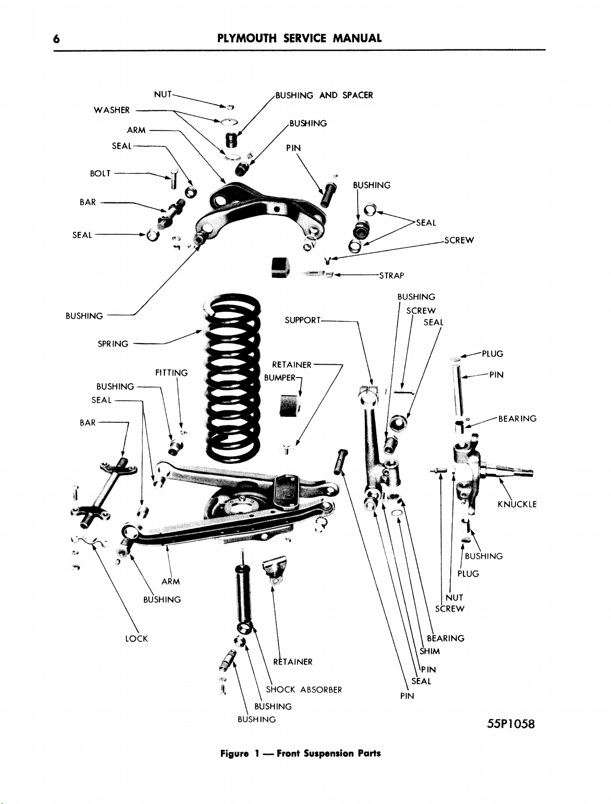
6.UpperControlArm14
7.UpperControlArmPin,BushingandDustSeal14
8.LowerControlArmandFrontSpring14
9.
FrontShockAbsorber15
10.
DiagnosisProcedures16
1.
FRONTWHEELALIGNMENT
Theneedforcheckingthealignmentofthefront
wheelsisusuallyindicatedbythewaythecar
steers,suchasa tendencyforthecartoleadto
oneside,ortowander.Certaintypesoftirewear,
suchastoe-inortoe-outwear,orcamberwear,
indicatetheneedforcheckingsomeofthefactors
ofwheelalignment.
Ifitisconsiderednecessarytocheckthewheel
alignmentofa newcar,itshouldberemembered
thatthefrontwheel suspensionpartsareclosely
fittedandtheirmovementis
stiff.
Asa result,a
newcarwillnotalwayssettletothepositionwhere
correctreadingscanbeobtained.Whenservicing
anewcar,itisbesttocheckonlythetoe-inofthe
frontwheels.Afterthecarhasbeendrivenabout
3,000miles,thestiffnessofnewpartswillbere-
lieved,andifwheelalignmentcorrectionsare
necessary,theycanbemadeatthenormalriding
level.
IMPORTANT
Frontwheel alignment equipment should be
checked frequently with the proper checking
equipment. Equipmentthat has
been
damaged
by dropping or rough handling should be care-
fully checked and adjusted before it is
used.
The floor must be level when using portable
equipment.
2.
FACTORSOFFRONTWHEEL
ALIGNMENT
Thefactorsoffrontwheelalignmentaregener-
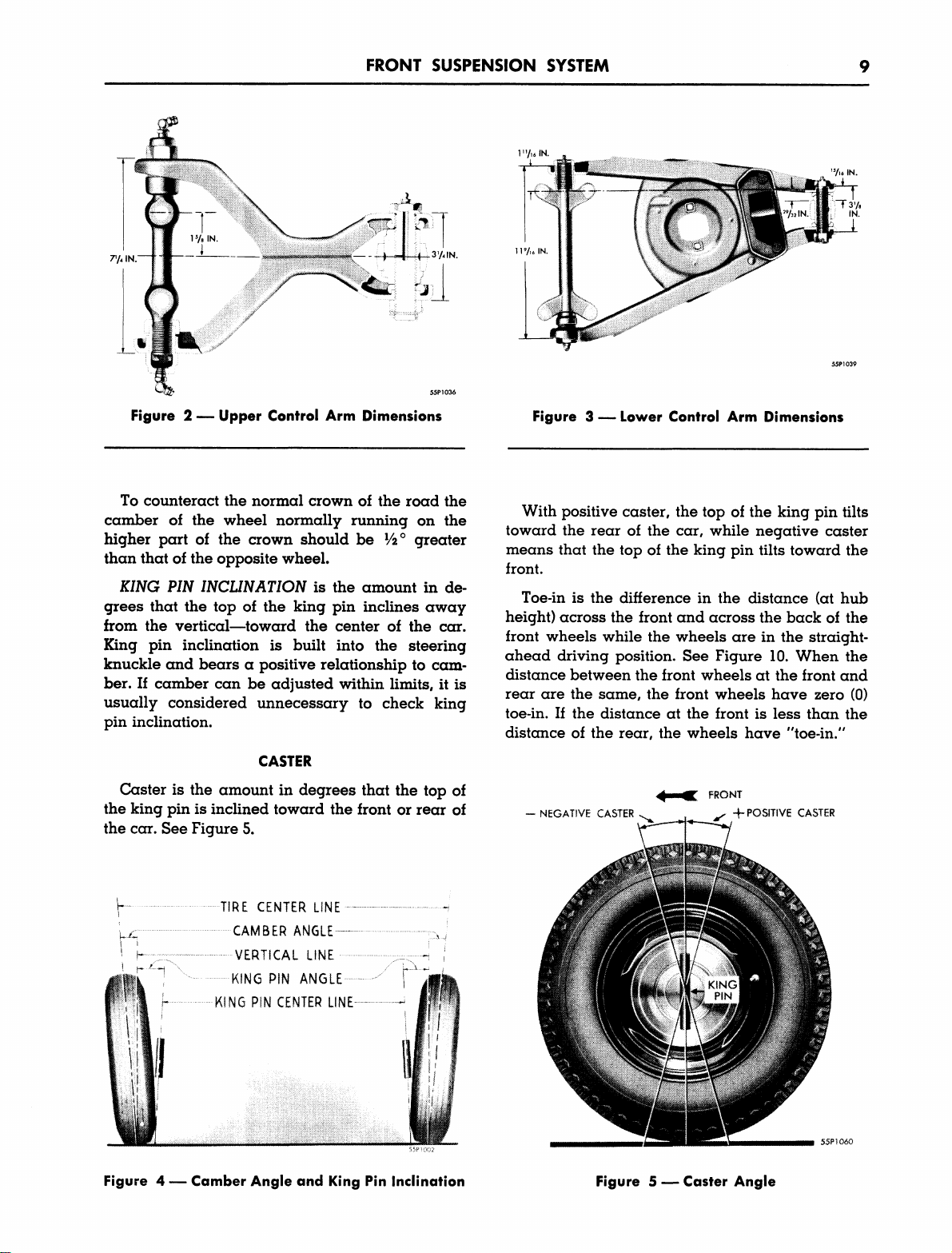
allyconsideredtobecamberandkingpininclina-
tion,
caster,toe-inofthefrontwheelsinthe
straight-aheadposition,andtoe-outofthefront
wheelsonturns.
Inadditiontothesefactors,thereareothercon-
ditionsthataffectsteeringcontrol.Theseare:im-
propertirepressure;wheelwobble;unbalanced
wheel andtireassemblies;saggedorbrokenfront
orrearsprings;damagedsteeringgearparts;
draggingbrakesorbentframe.
Frontwheelalignmentsettingsmustbeheldto
specificationswithinreasonablelimitsinorder
thatthevehiclemayexhibititsbeststeeringchar-
acteristicsandinordertoholdtherateandun-
evennessoftiretreadweartoa minimum.
Wheelalignmentmeasurementsshouldbetaken
withrecommendedtirepressureswithnopassen-
gerload,andwithcarstandinginitsnormallevel
positionwithnojacksunderit.Camber,casterand
toemeasurementsmustbemadewiththefront
wheelsonfloatingturn-tables.
CAMBERANDKINGPININCLINATION
CAMBER
istheamountindegreesthatthefront
wheelsinclinefromtheverticalwhenviewedfrom
thefrontofthecar.Seefigure4.Wheelswithposi-
tivecamberarefartherapartatthetopthanatthe
bottom.Wheelswithnegativecamberarefarther
apartatthebottomthanatthetop.
MyMopar.com

8PLYMOUTHSERVICEMANUAL
FRONTSUSPENSIONSYSTEM
DATA
AND
SPECIFICATIONS
Models
Type
Camber
Caster
Toe-In
Toe-OutonTurns
KingPinAngle
KingPinBushings—Ream
after installation
SteeringKnuckle
ThrustBearing
TieRods
ShortRod
LongRod
WheelBearingType
Tread
WheelBase
SwayEliminator
P-26-P-28P-27-P-29
CoilSpring—IndependentSuspension
—
Y/i
degreeonLeft
—
0 degreeonRight
-2to0 degrees
½inch
Withinsidewheel at20degrees,outsidewheel shouldbe
1712to 19degrees
5to6½degrees
Upper.7960to.7975in.
Lower.7960to.7975in.Upper—NeedleBearing
Lower—.7960to.7975in.
.005to.010inch
NominalLength12%in.
NominalLength33%in.
20%
in.
20%
in.
TaperedRoller
Front58.44in.
Rear58.50in.
115in.
Mountedonframeandconnectedtolowercontrolarmthrough
rubbercushions
TORQUESPECIFICATIONS
Lowercontrolarmbarbushing
Lowercontrolarmpin
Uppercontrolarmpivotbarbushing
Uppercontrolarmpin
Tierodclampbolts
Uppercontrolarmpivotbarbolts
Lowercontrolarmpivotbarbolts
165ft.lbs.(min.)
100to110ft.lbs.
120to140ft.lbs.
100to110ft.lbs.
10to15ft.lbs.
80ft.lbs.
60ft.lbs.
MyMopar.com

FRONTSUSPENSIONSYSTEM
7`/4
IN.
3'/«IN.
T'/ulN.
Vi«
•N.
Figure2 — UpperControlArmDimensionsFigure3 — LowerControlArmDimensions
Tocounteractthenormalcrownoftheroadthe
camberofthewheel normallyrunningonthe
higherpartofthecrownshouldbe½°greater
thanthatoftheoppositewheel.
KING PIN
INCLINATION
istheamountinde-
greesthatthetopofthekingpininclinesaway
fromthevertical—towardthecenterofthecar.
Kingpininclinationisbuiltintothesteering
knuckleandbearsa positiverelationshiptocam-
ber.Ifcambercanbeadjustedwithinlimits,itis
usuallyconsideredunnecessarytocheckking
pininclination.
CASTER
Casteristheamountindegreesthatthetopof
thekingpinisinclinedtowardthefrontorrearof
thecar.SeeFigure5.
TIRECENTERLINE™
CAMBER
ANGLE
—
VERTICALLINE
K!N6PINANGLE
KINGP\H CENTERLINE-
Withpositivecaster,thetopofthekingpintilts
towardtherearofthecar,whilenegativecaster
meansthatthetopofthekingpintiltstowardthe
front.
Toe-inisthedifferenceinthedistance(athub
height)acrossthefrontandacrossthebackofthe
frontwheelswhilethewheelsareinthestraight-
aheaddrivingposition.SeeFigure10.Whenthe
distancebetweenthefrontwheelsatthefrontand
reararethesame,thefrontwheelshavezero(0)
toe-in.Ifthedistanceatthefrontislessthanthe
distanceoftherear,thewheelshave"toe-in."
—NEGATIVECASTER
FRONT
4·POSITIVECASTER
Figure4 — CamberAngleandKingPinInclinationFigure5 — CasterAngle
MyMopar.com

10PLYMOUTHSERVICEMANUAL
TOE
.OUT
IFINDTHIS
|
•
DIFFERENCE
·
Figure6 — SteeringGeometryonTurns
COMPAR
Figure7 — MeasuringFrontSpringHeight
TOE-OUTONTURNS
Whenfrontwheelsareturnedtotherightorleft,
theyusuallytoe-out.SeeFigure6.Whenturning,
bothfrontwheelsmusttravelincircleswhichhave
acommoncenter.Thecircletraveledbytheinside
frontwheelhasa smallerradiusthanthatofthe
circletraveledbytheoutsidefrontwheel.Because
ofthis,theinsidefrontwheelmustturnfurther,
causingthefrontwheelstotoe-out.
3.FRONTWHEELALIGNMENT
CORRECTIONS
Beforeattemptingtocorrectthealignmentofthe
frontwheels,thetiresshouldbeproperlyinflated
andinspectedforwear.Aninspectionofthefront
suspensionsystemshouldbemadeforevidence
ofwear.Thecarshouldbeemptyofallluggageor
loadexceptthesparetire.(Wherea caroperates
undera loadedconditionatalltimesitisbestto
setwheelalignmentwiththisloadinthecar.)Set-
tlespringsandshockabsorbersintotheirnormal
positionsbybouncingfrontendof
carup
anddown
severaltimes.Thecarmustbeona levelsurface
beforeanycorrectionsaremade.
MEASURINGFRONTSPRINGHEIGHT
Tomeasurefrontspringheight,proceedasfol-
lows.
SeeFigure7:
1.
Findthedifferencebetweenthefollowing
measurementstakenatonelowercontrolarm.
(a)Fromfloortocenterofgreasefittinginthe
frontbushingofthelowercontrolarmbar.
(b)From
floor
tocenteroflowercontrolarmpin.
2.
Thenfindthedifferencebetweenthesame
measurementstaken
atthe
otherlowercontrol
arm.
3.
Comparethedifferenceinthemeasurements
ofonesideascomparedwiththeother.There
shouldbenomorethan¼"differencebetween
thesemeasurements.
Frontspringheightwillbeaffectediftherear
springheightvariesmorethan¾ inchononeside
ascomparedwiththeotherside.Comparerear
springheightbymeasuringwitha steeltapefrom
thespringplatestotheframeoneachsideofthe
car.
Coilspringsareidentifiedbypartnumbersnear
theendofthecoil.Themarksfollowingthe
stampednumberscorrespondtothelastdigitin
thepartnumber.Forexampleon6 cylinder
models,partnumber1618524willappearas
161852( ) ( ) ( ) ( ).
On8 cylindermodelspartnumber1618753will
appearas= 875( ) ( ) ( ).
Eachmarkfollowingthestampednumberon
thecoilindicatesonenumberhigher.Thepart
numberalsoindicatesa definitestepinrelationto
carheight,thehigherthenumber,thehigherthe
carwillberaised.
CHANGINGSPRINGHEIGHT
Carheightcanbechangedapproximately¾
inchbyusinga lowerorhigherpartnumber.For
example,ifa springwithtwomarksisreplaced
witha springofthesamepartnumberseriesthat
hasthreemarks,thecarheightonthatsidewillbe
increasedapproximately
%
inch.
MyMopar.com

FRONTSUSPENSIONSYSTEM11
CAMBERANDKINGPININCLINATION
Toadjustcamber,loosenlockscrew(Figure8),
andturntheeccentricbushing.Thecorrectsetting
canbeobtainedwithin½ revolutionineitherdi-
rectionfromthestartingpoint.Donotturnthe
eccentricbushinguntilitbindsagainsteitherside
oftheuppercontrolarmunderanycondition.Ad-
justcambertothecorrectspecificationsasshown
onpage8.Theleftsideshouldbeset½ degree
greaterthantherightsidetooffsetthetendency
ofthecartoleadtothesideona highlycrowned
road.
If
thecambercannotbeadjustedwithinstandard
limits,
andspringheighthasbeenchecked,meas-
urethekingpininclinationandinspectforbent
partsinthefrontsuspensionsystem.
CASTER
Thespecifiedcasterangleofminus(—)2 de-
greesto0degreeisobtainedbytheproperassem-
blyoftheupperandlowercontrolarms.Ifthe
casterangledoesnotcomewithinthese
limits,
look
forbentpartsinthefrontsuspensionsystem.
TOE-IN
J.
MEASURING TOE-IN
— Spinfrontwheels
andscribea thinlineinthecenterofthetreadof
eachtire.Placewheelsonturntablesandsetthem
inthestraight-aheadposition.Turnsteeringwheel
fulltravelinbothdirectionsthenreturnittomid-
travel,with
the
steeringwheel
in
thestraight-ahead
position.
Measurethedistanceathubheightbetween
pointsmarked"A"andpointsmarked"B."See
Figure10.Thedistancebetweenpoints
"A"
should
be¼"lessthanthedistancebetweenpoints"B."
2.
ADJUSTING TOE-IN — Withfrontwheelsin
straight-aheadposition,loosenclampingboltson
theendsofthetierodsandadjusttierodsanequal
amountinproperdirectionuntiltoe-inis¼".
Ifroadtestshowsthesteeringwheeltobeimprop-
erlycentered,adjustboththerodsanequalamount
untilthesteeringwheeliscentered.
Shorteningtheleftandlengtheningtheright
tie-rodwillmovethesteeringwheel clockwise.
Onefullturnofthetie-rodwillmovethesteering
wheelaboutthreeinches,measuredattherim.
AMBERADJUSTINGWRENCH
Figure8 — AdjustingCamberAngle
Figure9 — CheckingCamber
MEASUREDISTANCEBETWEEN"A
THEN
MEASUREDISTANCEBETWEEN"B
DISTANCE"A"SHOULD6£
!¾in.l£55THAN
DISTANCE••»"
Figure10— MeasuringToe-In
MyMopar.com

12PLYMOUTHSERVICEAAANUAL
Whenthetoe-inadjustmentiscorrect,position
theendsofthetierodsinthesocketssothatboth
studsareagainsteitherthefrontorbacksidesof
thesocketsandtightentheclampbolts.Thiswill
providesufficientangularrotationofthetierodon
theballstudsandpreventinterferenceonextreme
turns.
Tightenclampboltsto10to15footpounds.
Ifboltsaretightenedtoomuch,theclampwillbe
distorted,losingitsclampingaction.Alwaysre-
checkthemid-positionofsteeringwheelafter
adjustingtoe-in.
TOE-OUTONTURNS
Withthefrontwheelsonturntables,checkthe
outerwheelanglewithinnerwheelat20degrees.
Theturntableundertheouterwheelshouldindi-
cate17½to19degrees.
Ifthereadingisnotwithintheselimits,thesteer-
ingknucklearmorpitmanarmmaybebent.
4.TIERODENDS
REMOVAL
Iftheremovalofthetie
rod
endproves
to
bediffi-
cult,inserta prybarbetweenthetierodendand
thesteeringknucklearm.Thenjarthetierodend
loosebytappingontherearendofthesteering
knucklearmwitha hammer.SeeFigure11.
Tierod
endsshouldoperatefreely.Ifthereisany
evidenceofloosenessorbindingina tie-rodend,a
newoneshouldbeinstalled.
ASSEMBLY
Whennewtie
rod
endsareassembled
to
therod,
theendsmustbethreadedintherodanequal
amount.Clampboltsshouldbetightenedfrom10
to15footpounds.Ifboltsaretootight,clampwill
bedistortedandloseitsclampingaction.Always
makea finaladjustmentoftoe-inaftertierodends
havebeeninstalled.Thetierodendsmustbepo-
sitionedtoinsureequalclearancebetweenthe
socketsandballstudstopreventbinding.
5.STEERINGKNUCKLEAND
SUPPORT
REMOVAL
Whenitisnecessarytoserviceeitherthesteer-
ingknuckle,orthesupportarm,itisrecommended
thatthesteeringknucklesupport,steeringknuckle
andbrakesupportberemovedasanassemblyso
thatrepairscanbemadeona bench.Always
installnewbushings,sealsandlockpinswhen
overhaulingthesteeringknuckleandsupport
assembly.
Kingpinbushingsshouldberemovedandin-
stalledwiththeuseoftoolC-328.SeeFigures12
and13.
Thistoolremovesorinstallseitherbushingsor
needlebearingsinsteeringknuckle.
34x146
Figure11— RemovingtieRodEndFrom
SteeringKnuckleArm
Figure12— RemovingSteeringKnuckleBushings
withSpecialToolC¯328
(Useofpropersizeadaptor(2)willremoveoldpart(1)
withoutdamagingsteeringknuckle.)
MyMopar.com

FRONTSUSPENSIONSYSTEM13
I7XW
Figure13— InstallingSteeringKnuckleBushings
withSpecialToolC-328
(Useofpropersizeadaptor(1)fitsbushingorbearing(2)
andfollowsitthroughtoitsproperlocation.)
IDfcNT!F¡CAÍ¡ON
MARK
BUSHING
IDENTIFICATION
Figure14— KingPinBushingsand
BearingInstalled
NOTE
On8 cylinder models, the upper steering
knuckle location has a needle bearing in place
of a bushing.
INSTALLINGSTEERINGKNUCKLEBUSHINGS
Installtheupperbushingfromthetopoíthe
steeringknuckle.Installupperandlowerbushing
withthegreasegroovetowardthewelchplugas
showninFigure14.Installlowerbushingandline
ream
both
bushingswithreamerandpilotbushing,
toolC-691.SeeFigure15.
NOTE
On8 cylinder models the upper bearing
must be removed during this operation and
temporarily replaced with the pilot bushing
to align the
reamer.
Reamer
can be used with-
out pilot bushing on cars using two bushings.
Whena welchplughasbeeninstalledand
properlyseatedwitha special toolC-618,besure
tostakeit.SeeFigure16.
TOOLC369
Figure15— LineReamingKingPinBushings
withSpecialToolC-369
STAKEINPLA·lI
ASSHOWN
STAKESECURELY
4PLACESAS»
SHOWNBOTH'
ENDS
Figure16—WelchPlugInstalledandKingPin
LockPinStaked
MyMopar.com

14PLYMOUTHSERVICEMANUAL
6.UPPERCONTROLARM
Basicallytheuppercontrolarmremainsthe
sameasthoseusedinpreviousmodels,however
itisapproximately¼"widerandismountedtothe
framewithtwoboltsinsteadoffour.Duetothese
changesthemethodofcenteringthepivotbaris
somewhatdifferent,therefore,itisnolongerpos-
sibletousetoolC-608forlocatingthecenter.Itcan
beused,however,tomaintainthefixeddimension
of7¼inchesoftheuppercontrolarmwhen
newpivotbar,bushings,etc.areinstalled.See
Figure2.
To
installa newpivotbarandbushingsafterthe
removaloftheothersproceedasfollows:
Centerthepivotbarwithdustsealsinstalledin
thecontrolarm(as
it.
wouldbewheninstalledin
vehicles).Whileinthiscenteredposition,start
bushingsevenlyonbothendsofthepivotbarand
lubricatethemwitha suitablelubricant.Placetool
C-608onthepivotbarandexpandthetwojawsof
thetoolbytighteningtheexpanderwedgenutun-
tilthejawsofthetoolarejustsnugagainstthe
insideofthecontrolarm.
CAUTION
Make sure jaws of tool are seating fully on
inside face and not binding against control
arm flange.
Clamptoolandcontrolarmassemblyinvise
makingsurepivotbarremainedcentered.Thread
thebushingsintoeachsideofthecontrolarmuntil
theshoulderofthebushingscontactthesurfaceof
thecontrol
arm.
Tighten
with
a torquewrenchfrom
120to130footpounds.Removetoolandcheck
operationofthepivotbarforfreemovement(only
amoderategripshouldberequiredtoturnthe
pivotbar).
NOTE
Pivot bar may if necessary be rotated 1 turn
in either direction to correct a slight centering
error.
7. UPPERCONTROLARMPIN,
BUSHINGANDDUSTSEAL
Whenreplacingthepin,bushingordustseal
oftheuppercontrolarm,supportcarunderneath
lowercontrolarm,andremovethewheelandtire
assembly.Then,removethepivotbarattaching
boltsandliftthecontrolarmupandoutward.
Toinstalltheneweccentricbushinginthesteer-
ingknucklesupport,placeonesealonthebushing
atthehexagonalend.Placetheothersealonthe
oppositebossoftheuppercontrolarm.
ThenwithtoolC-736,depresstheouteredgeof
lipoftheseal.SeeFigure17.Slidethecontrolarm
andsealontothesteeringknucklesupportuntil
bothsealsfitsnuglyoverthebushing.Makesure
thepinholeisinalignment.Next,removethetool
andinstallthepin.
Lineupthepivotbarholeswiththeframecross
memberholesandinstalltheattachingboltsand
tighten.
8.LOWERCONTROLARMAND
FRONTSPRING
REMOVAL
Whenremovinga lowercontrolarmassembly
andfrontspring,removetheshockabsorberand
wheelandtire.Raisecarandplacea jackorsup-
portunderthelowercontrolarmtoberemoved.
Placejackorsupportunderframeneartheup-
sweepatthefront.Supportthelowercontrolarm
andlowerthecar.Removethecontrolarmpinand
raisefrontendofcartorelievepressureonfront
spring.Whenpressureisofffrontspring,remove
supportwhichwasplacedundercontrolarm,
swingarmdownandremovefrontspring.Thecon-
trolarmcanthenberemoved.
\fcAiANDB'<`>HING
IN'
lÀÍUNK~P ' I
46x43
Figure17— InstallingUpperControlArmPin
BushingandDustSealswithSpecialToolC-736
MyMopar.com

FRONTSUSPENSIONSYSTEM15
INSTALLATION
Whenoverhaulingthelowercontrolarmassem-
bly,alwaysinstallnewpivotbarbushingsand
dustseals.
Installdustsealsonpivotbarandpositionpivot
barinthecontrolarm.AssembletoolC-594tothe
pivotbar.
Thelowercontrolarmon6 and8 cylindermod-
els,
basicallyandappearancewiseremainsthe
same.Thespringseatismountedtothelowerside
ofthecontrolarm.Thelowercontrolarmpivotbar
mountingboltlocationsarethesameon6 and8
cylindermodels.Duetothelocationofthese
mountingholes,toolC-594cannotbeusedfor
centeringthelowerpivotbar,butcanbeused
tomaintainthesetdimensionofthecontrol
armwheninstallingnewpivotbar,etc.Tocen-
tera replacementpivotbar,proceedasfollows:
(SeeFig.3).
Installdustsealsonpivotbarandclampinvise,
(flatmountingsurfacedown).Centerlowercon-
trolarmonpivotbar(bottomofspringseatupand
steeringknucklesupportendrestingonbench).
Whileinthiscenteredposition,startbushings
evenlyonbothendsofpivotbarandlubricate
themwitha suitablelubricant.
ModifytoolC-594byremovinglocatingstuds
(savestudsforuseonpreviousmodels)andplace
inpositiononpivotbar(openendsoftooldown).
Makingsuretoolremains
in
place,threadthebush-
ing(onetoyourright)intocontrolarmuntilthe
shoulderofthebushingcontactsmachinedsurface
ofcontrolarm.Tightento180footpounds.
Removetoolfromassemblyandreverseposition
ofassembly
in
vise(topofspringseatupassembly
restingonbench).RepositiontoolC-594onpivot
barandthreadremainingbushingintocontrolarm
usingsametorque.Removetoolandassembly
fromviseandcheckpivotbarforfreemovement.
Pivot bar
direction to may be
correct
NOTE
rotated one turn in
aslight centering either
error.
Placea jackorsupportunderthelowercontrol
arm,
andlowerthecar
to
compressthespring.Line
uptheknucklesupportbushingandcontrolarm.
Installpinandtightennutto90-110footpounds.
IMPORTANT
Make certain the spring is properly seated
at both top and bottom.
9.
FRONTSHOCKABSORBER
REMOVAL
Theupperendofthepistonrodhastwoflatsto
providea meansofholdingtheshockabsorber
whileremovingtheuppernut.Afterremovingthe
uppernut,removethetwocapscrewsfromthe
lowersupportbracketandremovetheshockab-
sorberbypullingitdownwardthroughthecoil
spring.
Thelowerbushingisassembledtotheshock
absorberbypressingitintotheeyewitha press
fit.Endpressuremaybeappliedonlytotheouter
sleeveofthebushingassembly.Thiscanbeeasily
doneinanarborpressbyusinga tubulardrift
havinga smallclearanceintheshockabsorber
eyeuntilitiscenteredorbyusingtoolC-3413.
Toreplaceanupperrubberbushing,removein-
nersleeveandinstallnewbushinginframe.
CAUTION
Oil, soap, or other lubricants, except
water,
must
not be
used.
The
bushing
assembly
should
be thoroughly cleaned before installation.
INSTALLATION
Toreplaceshockabsorberassemblyextend
pistonrodfullyandplacelowerretainer(cup
washer)concavesideuponpistonrod.
UPPER
MOUNTING
LOWERMOUNTING
ASSEMBLY
SCREW
LOCKWASHER55PJ014
Figure18— FrontShockAbsorberInstallation
MyMopar.com

16PLYMOUTHSERVICEMANUAL
Insertshockabsorberthroughopeninginspring
seatsopistonrodentersupperbushing.Installthe
twolowermountingscrewsandtorqueto35foot
pounds.
Installupperretainer(cupwasher)concaveside
downandnut.Tightennutto35footpounds.
CAUTION
Donot lubricate either the shock absorber,
piston rod or the rubber bushing.
10.
DIAGNOSISPROCEDURES
CARLEADSTOONESIDE
Thetendencyofa cartoleadtoonesidecon-
tinuouslyissometimesreferredtoas"pullingto
theleft,"or"pullingtotheright."Besuretode-
terminewhethertheconditionisduetodriving
onhighlycrownedroads.
J.
CAMBER
AND CASTER — Ifcamberand
casterisnotequaloneachside,thecarwilllead
toonesideona levelroad.
Withunequalcamber,thecarmayleadtothe
sidewhichhasthehighestcamberreading.Ifcas-
ter
isnotequal,thecarmaylead
to
thesidehaving
thelowestcasterreading.
Onmostcars,thecambersettingshouldagree
withthespecificationsshownonpage8,butwhen
thecarisdrivenona highlycrownedroad,the
cambercanbeincreasedontheleftside.However,
thecamberfortheleftwheel shouldnotbemore
than½ degreegreaterthanthatfortherightwheel
withinthespecifiedlimits.Ifthecambersetting
exceedsthisrecommendation,excessivewearon
theleftfronttiremayresult.
2.
TIRES —
Unequaltirepressurewillcausethe
cartoleadtothesidehavingthelowestpressure.
3.
FRAME
AND
SUSPENSION UNITS
— Bent
suspensionparts,orunequalwheelbasemaycre-
atea change
in
camberandcastergreatenoughto
causethecartopulltooneside.Tocheckfor
theseconditions,measurethewheelbase,center-
to-center,betweenthefrontandrearwheelson
bothsides.Thesemeasurementsshouldbeequal.
Iftheyarenot,lookfor:A brokenmainleafin
rearspring;a brokencenterboltinrearspring;
bentpartsinfrontsuspensionsystem;ora bent
frame.
4.
BRAKES
— Inspecttheadjustmentofeach
frontandrearwheelbrakefor"Dragging."
5.
STEERING TUBE
AND WORM
ASSEMBLY—
Abentsteeringtubeandwormassemblywill
causehardsteeringandmayresultinthecar
pullingtooneside.Totestforthiscondition,jack
upthefrontendofthecarandturnsteeringwheel
toextremerightandleft.Ifintermittentdragis
felt,tubemaybebent.
WANDER
Theterm"wander"meansthetendencyofthe
cartodriftslightlytooneside,thentotheother,
undernormaldrivingconditionswhilethedriver
attemptstosteerstraightahead.
Thisconditionshouldnotbeconfusedwithnor-
malwandercausedbyhighorgustywindsstrik-
ingthesideofthecarwhendrivingathighspeeds.
J.
KING PIN BUSHINGS
AND
STEERING
CON-
NECTIONS
— Tocheckkingpinbushingsfor
looseness,jackupthefrontendofthecarand
movewheelsinandout.Thecondition,ifpresent,
canbedeterminedby"feel."
Iftightnessappearstooriginateinthesteering
gearorsteeringcolumn,disconnectthesteering
geararmandturnthesteeringwheel,tocheck
fora bindinthesteeringcolumn.
2.
STEERING WHEEL
— Animproperlycen-
teredsteeringwheel willgivetheeffectofwander.
Thesteeringwheeliscorrectlycenteredwhenthe
spokesareequallypositioned,withthefront
wheelspointingstraightahead.
3.
TIRES
— A smoothtreadonfronttires,may
causewanderwhenthecarisdrivenovergravel
or"black-top"roads.Under-inflationofbothfront
orreartiresmaycauseunstablesteeringandre-
sultinwander.
4.
CASTER — Bent
frontwheel suspensionparts,
orunequalwheelbase,maycreatea changein
thecastergreatenough
to
causethecar
to
wander.
Tocheckfortheseconditions,measurethewheel-
base,center-to-centerbetweenthefrontandrear
wheelsonbothsides.Thesemeasurementsshould
beequal.Iftheyarenot,lookfor:A brokenmain
leafinrearspring;a brokencenterboltinrear
spring;bentpartsinfrontsuspensionsystem;or
abentframe.
FRONTENDNOISES
Thisparagraphisconfinedonlytothosenoises
whichcouldoriginateinthefrontwheelsuspen-
sionsystem.Thesenoisesshouldnotbeconfused
withthosecomingfromotherpartsofthecar.The
possiblepointswherenoisecanoriginateare:
MyMopar.com

FRONTSUSPENSIONSYSTEM17
J.
UPPER
and LOWER CONTROL ARMS — In-
spectforloosenessintheupperandlowercontrol
armsbymovingthesteeringknucklesupportback
andforthwitha prybar.Loosenesscanbede-
terminedbyfeel#orpossiblybyshinyspotsonthe
cambereccentricbushingoneithersideofthe
wheel support.
Built-inclearanceisdesignedintothethreaded
bushingsofthefrontsuspensionlinkage
to
prevent
bindingofthejointsunderdeflection.Partsofthe
linkageshouldnotbereplacedunlesstheycause
noiseorunstablesteering,andshouldneverbe
replacedwithtightfittingpinsorbushings.
Thethreadedbushingsofthefrontsuspension
systemrequiremoreclearancethana smoothpin
andbushingtypejoint.Thethreadedpin"rides"
ontheV shapedthreadcutinthebushing.With
theweightofthecaronthebushing,thesideof
thepinthreadbearsagainstthesideofthethread
cutinthebushing.Newpartsshouldnotbein-
stalledunlessthereisendwisemovementofthe
pininthebushing.SeeFigure19.
2.
WHEEL BEARINGS
— Todetermineifthe
wheel bearingsarewornordamaged,roadtest
thecarandapplybrakes.Thisactionwilltake
someoftheloadoffthewheelbearings,andnoise
ifpresent,willdiminish,indicatingthatthebear-
NECESSARY
CLEARANCE
BUSHING
NOCLEARANCEONWORKINGSIDEOFPIN
INBUSHING-"V"THREADDESIGNPREVENTSEND
PLAYOFPINWHENUNDERNORMALLOAD
45X146
Figure19— NormalClearanceBetweenPin
andBushing
ingsareatfault.Raisefrontwheelsandcheck
forloosebearingsbymovingwheelsinandout.
Ifa wheelisloose,removeitandcheckcondition
ofbearingsandbearingcupsbeforetightening
thebearings.
MyMopar.com

18PLYMOUTHSERVICEMANUAL
REARAXLE
DATAANDSPECIFICATIONS
Models
Type
DriveGearType
RatiosConventional
Overdrive
Powerîlite
RingGeartoDrivePinionBacklash
DifferentialCaseRun-Out
DifferentialSideGearClearance
AxleShaftEndPlay
DrivePinionBearingPreload
LubricantCapacity
P-26—P-28P-27—P-29
Semi-Floating
Hypoid
3.73to1.
Optional—Mountains
andhillycountry
4.1to1.
4.1to1.
3.73to1.3.54to1.
Optional—Mountains
andhillycountry
3.9to1.
.006to.010in.
0to.003in.
.004to.012in.
.003to.008in.
20-30in.lbs.withoutseal(SeePage24)
3½pts.
TORQUESPECIFICATIONS
AxleShaftNuts
RearAxleRingGearBoltNuts
DifferentialBearingCapScrews
DrivePinionFlangeNut
142ft.lbs.(min.)
35to40ft.lbs.
85to90ft.lbs.
250to280ft.lbs.
MyMopar.com

19
SECTIONII
REARAXLE
Page
DataandSpecifications18
1.
AxleDriveShafts,SealsandBearings19
2.
DifferentialandCarrierAssembly21
3.DrivePinionBearingOilSeal30
4.DiagnosisProcedures31
1.
AXLEDRIVESHAFTS,SEALS
ANDBEARINGS
AXLESHAFTENDPLAY
CHECKING
ENDPLAY — Axleshaftendplay
is.003to.008inchwiththelowlimitpreferred.
Measureendplaybyclampinga dialgaugeon
thebrakesupport,withthewheel,hubanddrum
assemblyremoved.Placeindicatorbuttonagainst
endofaxleshaft.Thetotalendplayofbothaxle
shaftswillberecordedonthegaugewhenthe
shaftismovedinandout.SeeFigure1.
ADJUSTING END PLAY—End
playiscontrolled
byshimsbetweenthebrakesupportplateandthe
axlehousingflange.Usespecial toolC-745topro-
tectoilsealwhenremovingbrakesupportplate.
Ifnecessary
to
removemorethan
.020
inch
in
shims
todecreaseendplay,removeanequalamountof
shimsonbothsidestoretainthecentralposition
ofthethrustblock.Tootightanadjustmentwill
resultintheoverloadingofthewheelbearings.
AXLESHAFTREMOVAL
Removewheel,hubanddrumassembly,using
wheelpullerC-845.SeeFigure2.
CAUTION
Donot use knock-out type pullers or strike
endof axle shaft to
loosen
hub.
This
may dam-
age the rear wheel bearings, thrust blockand
opposite brake support plate.
Theaxlebearingouteroilsealismountedin
thebrakesupport.Toprotectsealagainstdamage
UNIVERSALWHfcü
AND
HUBPULLER
•J-
46x93
Figure1 — MeasuringAxleShaftEndPlayFigure2 — RemoveWheelandHub
ToolShownisNo.C-845
MyMopar.com
This manual suits for next models
5
Table of contents
Other Plymouth Automobile manuals

Plymouth
Plymouth Plaza 1957 User manual

Plymouth
Plymouth Valiant 1968 User manual

Plymouth
Plymouth Valiant 200 1969 User manual

Plymouth
Plymouth Valiant V-100 1965 User manual

Plymouth
Plymouth Gran Fury 1980 User manual

Plymouth
Plymouth Fury 1369 User manual

Plymouth
Plymouth Pl4S User manual

Plymouth
Plymouth Gran Fury1976 User manual

Plymouth
Plymouth SAVOY 1961 Operating manual

Plymouth
Plymouth Cranbrook User manual