Plymovent CONTROLPRO/DILUTER User manual

www.plymovent.com
EN Control panel with separate HMI
NL Besturingskast met aparte HMI
PL Panel sterowania z osobnym interfejsem HMI
EN Installation manual
NL Installatiehandleiding
PL
CONTROLPRO/DILUTER

010219/0 ControlPro/Diluter 1
EN – ORIGINAL INSTRUCTION
All rights reserved. The information given in this document has been collected for the general convenience of our clients. It has been based on general data pertaining to construction material
properties and working methods known to us at the time of issue of the document and is therefore subject at any time to change or amendment and the right to change or amend is hereby expressly
reserved. The instructions in this publication only serve as a guideline for installation, use, maintenance and repair of the product mentioned on the cover page of this document. This publication is to
be used for the standard model of the product of the type given on the cover page. Thus the manufacturer cannot be held responsible for any damage resulting from the application of this publication
to the version actually delivered to you. This publication has been written with great care. However, the manufacturer cannot be held responsible, either for any errors occurring in this publication or
for their consequences.
To improve comprehension for people whose rst language is not English, we have written parts of this manual in Simplied Technical English (STE). STE is a controlled language
originally developed for aerospace industry maintenance manuals. It offers a carefully limited and standardized subset of English, along with specic writing rules.
NL – VERTALING VAN DE OORSPRONKELIJKE GEBRUIKSAANWIJZING
Alle rechten voorbehouden. De in deze handleiding verstrekte informatie is gebaseerd op algemene gegevens aangaande de ons ten tijde van verschijnen bekende constructies, materiaaleigenschappen
en werkmethoden, zodat wijzingen worden voorbehouden. Om deze reden dienen de gegeven instructies slechts als richtlijn voor het installeren, gebruiken, onderhouden en repareren van het op de
voorzijde van dit document vermelde product. Deze handleiding is geldig voor het product in de standaard uitvoering. De fabrikant kan derhalve niet aansprakelijk worden gesteld voor eventuele schade
voortvloeiend uit de van de standaard uitvoering afwijkende specicaties van het aan u geleverde product. Deze handleiding is met alle mogelijke zorg samengesteld, maar de fabrikant kan geen
verantwoording op zich nemen voor eventuele fouten in deze handleiding of voor de gevolgen daarvan.
PL | TŁUMACZENIE ORYGINALNEJ INSTUKCJI
Wszelkie prawa zastrzeżone. Informacje zawarte w niniejszym dokumencie zostały zebrane dla ogólnej wygody naszych klientów. Został on oparty na ogólnych danych dotyczących właściwości
użytych materiałów konstrukcyjnych i metod pracy znanych nam w momencie wystawienia dokumentu i podlega zatem w każdej chwili zmianie. Prawo do zmiany lub uzupełnienia zostaje niniejszym
wyraźnie zastrzeżone. Instrukcje zawarte w niniejszej publikacji służą jedynie jako wytyczne dla instalacji, eksploatacji, konserwacji i napraw produktu wymienionego na stronie tytułowej niniejszego
dokumentu. Publikacja ta ma być stosowany do standardowego modelu produktu, typu podanego na pierwszej stronie. W ten sposób producent nie może ponosić odpowiedzialności za szkody wynikłe
ze stosowania niniejszej publikacji do wersji faktycznie dostarczonej do użytkownika. Niniejsza publikacja została napisana z wielką starannością. Jednak producent nie może być pociągnięty do
odpowiedzialności za jakiekolwiek błędy zawarte w niniejszej publikacji lub ich konsekwencje.

010219/0 ControlPro/Diluter 2
ENGLISH Page NEDERLANDS Pag. POLSKI Strona
Preface 3 Voorwoord 14 Wprowadzenie 25
1. Introduction 3 1. Inleiding 14 25
2. Product description 4 2. Productbeschrijving 15 2. Opis produktu 26
3. Safety instructions 4 3. Veiligheidsvoorschriften 15 26
4. Installation 4 4. Installatie 16 4. Instalacja 27
5. Commissioning 10 5. Ingebruikname 21 5. Uruchomienie 32
6. Use 11 6. Gebruik 22 33
7. Maintenance 12 7. Onderhoud 23 34
8. Troubleshooting 12 8. Verhelpen van storingen 23 34
9. Spare parts 13 9. Reserveonderdelen 24 35
10. Electrical diagram 13 10. Elektrisch schema 24 10. Schemat elektryczny 35
11. Disposal 13 11. Afdanken 24 11. Utylizacja 35
CE declaration 13 CE-verklaring 24 Deklaracja CE 35
TABLE OF CONTENTS

010219/0 ControlPro/Diluter EN - 3
PREFACE
Using this manual
This manual is intended to be used as a work of reference for
professional, well trained and authorised users to be able to
safely install, use, maintain and repair the product mentioned
on the cover of this document.
Pictograms and symbols
The following pictograms and symbols are used in this manual:
TIP
Suggestions and recommendations to simplify
carrying out tasks and actions.
ATTENTION
A remark with additional information for the user. A
remark brings possible problems to the user’s
attention.
CAUTION
Procedures, if not carried out with the necessary
caution, could damage the product, the workshop or
the environment.
WARNING
Procedures which, if not carried out with the
necessary caution, may damage the product or
cause serious personal injury.
CAUTION
Denotes risk of electric shock.
Text indicators
Listings indicated by “-” (hyphen) concern enumerations.
Listings indicated by “•” (bullet point) describe steps to
perform.
Product indications / Abbreviations
Product type: Equals to:
- ControlPro/Panel Panel
- ControlPro/HMI HMI1
- SCS-Diluter PRO SCS-Diluter
1 INTRODUCTION
1.1 Identication of the product
following data:
- product name
- serial number
- supply voltage and frequency
- power consumption
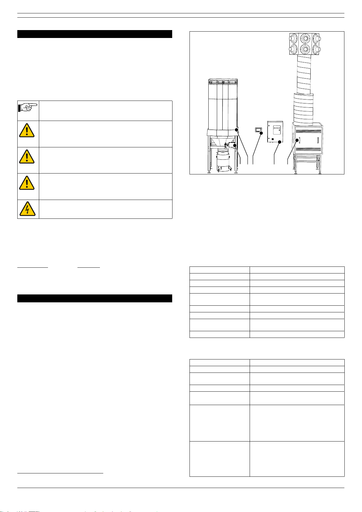
1.2 General description
ControlPro/Diluter of Plymovent is an intelligent control panel
with an integrated frequency inverter and a separate HMI, that
is supplied including the required connection cables. This
system controls the fan and the compressed air valves of the
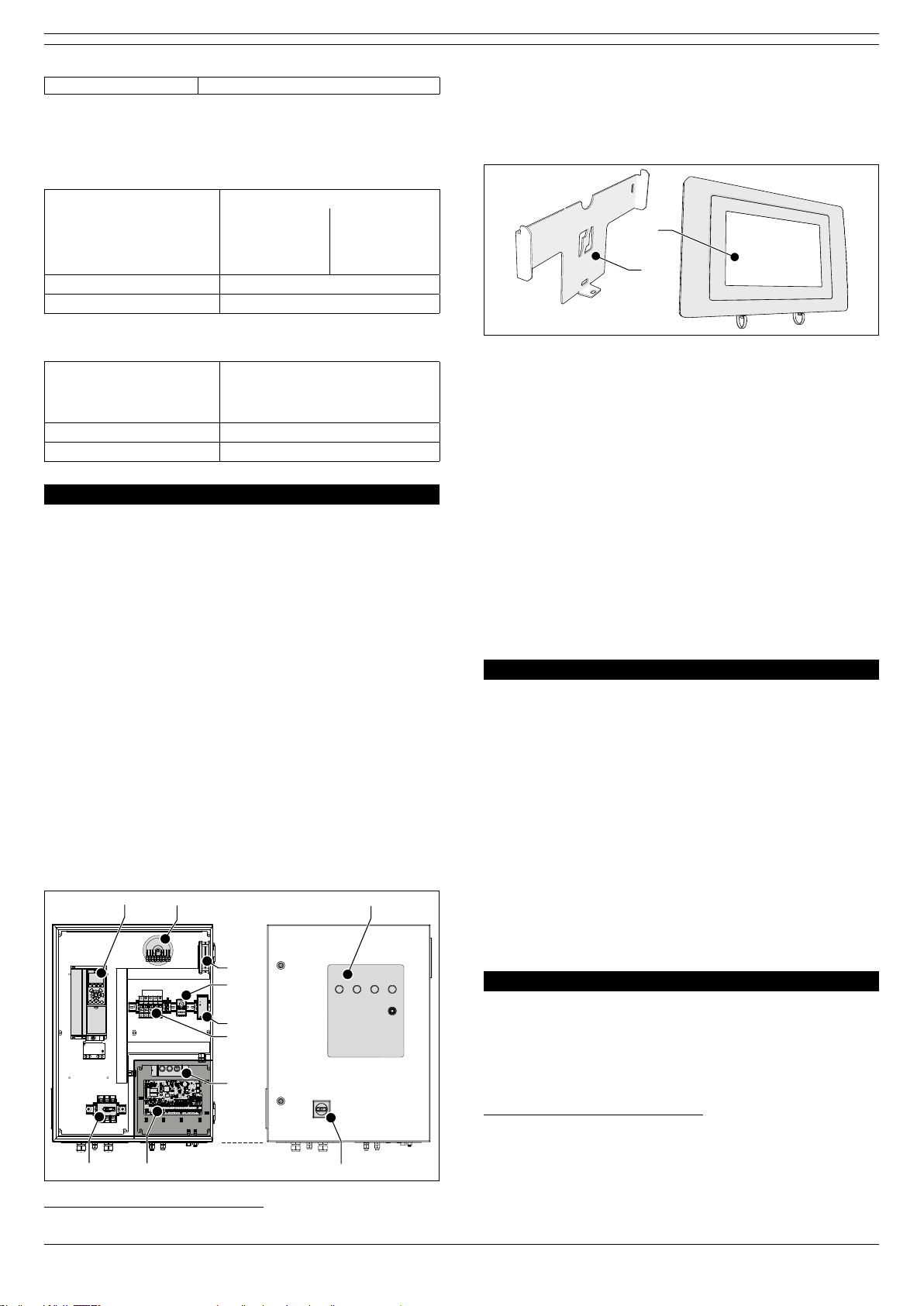
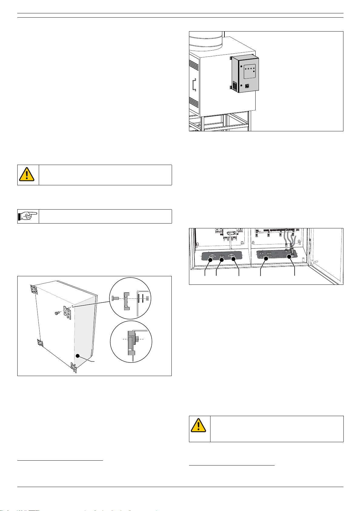
The control panel contains a frequency inverter and is divided
in two compartments (high voltage and low voltage).
Fig. 1.2
A Junction box CB-SCS
B Filter system SCS-Diluter
C HMI
D Panel [control panel]
E Extraction fan
1. Human Machine Interface
Fig. 1.2
B C D EA
A
B
CD
E
F
GH
SCS-Diluter + ControlPro/Diluter
1.3 Options and accessories
The following products can be obtained as an option and/or
accessory:
- Panel HMI cable 30 or 60 m (98 or 197 ft), instead of
standard length 15 m (49 ft)
- LightTower
- external pressure sensors (PT-1000 or PT-2500)
1.4 Technical specications
1.4.1 ControlPro/Panel
Dimensions refer to Fig. I on page 36
Weight 55 kg (121 lbs)
Material of housing sheet metal
Protection class IP 54
Input voltage 400V3ph/50Hz | 480V/3ph/60Hz |
600V/3ph/60Hz
Internal operating voltage 24 VDC (controls) | 115V / 230V (cooling fan)
Power consumption max. 7,5 kW
Internal pressure sensors
pressure and fan pressure)
400V: CE | 480V / 600V: cULus (UL 508A)
1.4.2 ControlPro/HMI
Dimensions 255 x 165 x 125 mm (10.0 x 6.5 x 4.9 in.)
Weight 900 g (2 lbs.)
Material of housing
-
PC/ABS
- UL94 V-0
Operating voltage 24 VDC (+/- 15%)
Power consumption -
- display on: max. 5 W
External connectors - CAN + power (connection to Panel)
[M12-5p shielded connector]
- USB 2.0 (host only)
[USB A receptacle, with dust cap]
- ethernet 10/100 Mbit/s
[RJ45, shielded, with dust cap]
Display:
- size
- type
- brightness
- colour
- resolution
- 7”
- resistive touch screen
- 300 cd/m²
- 262K
- 800 x 480 pixels

010219/0 ControlPro/Diluter EN - 4
CE
1.5 Ambient conditions
1.5.1 ControlPro/Panel
Pressure sensors:
Ambient temperature: internal external (option)
- min.
- nom.
- max.
0°C (32°F)
+20°C (68°F)
+50°C (122°F)
-20°C (-4°F)
+20°C (68°F)
+50°C (158°F)
Max. relative humidity 80%
Suitable for outdoor use no
1.5.2 ControlPro/HMI
Ambient temperature:
- min.
- nom.
- max.
0°C (32°F)
+20°C (68°F)
+50°C (122°F)
Max. relative humidity 80%
Suitable for outdoor use no
2 PRODUCT DESCRIPTION
2.1 Components
The product consists of the following main components and
elements:
2.1.1 ControlPro/Panel
Fig. 2.1
High voltage compartment
A VFD (frequency inverter)
B Transformer
C Cooling fan
D Thermostat
E Switch mode power supply
F Circuit protectors2
G Main switch (interior parts)
Low voltage compartment
H PC board
I Manual controls
Outside
J Status panel
K Main switch (exterior parts)
Fig. 2.1
A B
G
I
F
D
C
H
J
K
E
Main components Panel
2. CE (400V): circuit breakers | UL (480/600V): fuses
2.1.2 ControlPro/HMI
Fig. 2.2
A Touch screen
B Mounting bracket
Fig. 2.2
A
B
Main components HMI
2.1.3 Connection cables
- Panel HMI cable
- motor cable
- PTC cable
- control cable
2.2 Operation
system SCS-Diluter and the connected extraction fan. It
contains an extensive feature package to monitor and arrange
user-friendly HMI you can program all desired parameters. The
HMI gives a clear insight into the system status and
performance at all times.
ControlPro allows for remote access via a network connection.
3 SAFETY INSTRUCTIONS
General
SCS-Diluter of Plymovent. The safety instructions written in
the related manuals apply to the ControlPro/Diluter as well.
Intended use3
The product has been designed exclusively as control
Plymovent with the connected extraction fan. Using the
product for other purposes is considered contrary to its
intended use. The manufacturer accepts no liability for any
damage or injury resulting from such use. The product has
been built in accordance with state-of-the-art standards and
recognised safety regulations. Only use this product when in
technically perfect condition in accordance with its intended
use and the instructions explained in the user manual.
4 INSTALLATION
4.1 Tools and requirements
You need the following tools to install the products:
- basic tools
- tools for electrical connections4
3. “Intended use” as explained in EN-ISO 12100-1 is the use for which the
directions in the sales brochure. In case of doubt it is the use which can be
deduced from the construction, the model and the function of the technical
product which is considered normal use. Operating the machine within the
limits of its intended use also involves observing the instructions in the user
manual.
4. E.g. heat gun, cable stripping tool

010219/0 ControlPro/Diluter EN - 5
4.1.1 To be sourced locally
Mounting material5:
- to install the Panel to the fan housing or to the wall
(hardware max. Ø 10 mm)
- to install the HMI to the wall (head height of screws max. 6
mm, Ø max. 4 mm)
Connection cables6:
- refer to Table I
If necessary:
- additional cable glands M16
Optional (for remote access to HMI via network):
- ethernet cable, min. CAT 5E shielded
4.2 Unpacking
For the complete scope of supply, refer to the manual
SCS-Diluter.
4.3 Mounting
ATTENTION
Do not expose any component of ControlPro to
vibrations or heat radiation.
You must install the Panel and HMI at a clearly visible and
accessible position.
We recommend to install the Panel on the side of
the fan housing.
4.3.1 ControlPro/Panel
To install the Panel, do the following.
Fig. 4.3
• Attach the mounting brackets (A) to the Panel with the
supplied mounting material (B).
Fig. 4.3
B (4x)
A (4x)
Mounting brackets
Fig. 4.4
• Install the Panel to the fan housing or to the wall. Make
sure that it is level.
5. The type of mounting material depends on the wall type
6. Number and type of cables depend on the selected options and control
equipment
Fig. 4.4
B (4x)
A (4x)
Mounting of the Panel to the fan housing
The housing contains two removable bottom plates, that
contain the following cable glands and connectors:
Fig. 4.3
High voltage compartment (left bottom plate)
A Cable gland M25 for the motor cable
B Cable gland M16 for the PTC cable
C Cable gland M25 for the mains cord
Low voltage compartment (right bottom plate)
D Universal cable glands M16 (4)
E 7
Fig. 4.3
A B C D E
Bottom plates
Table I on page 38 gives an overview of the necessary and
optional cables that you need to install the system.
• Depending on the selected options, determine the number
and type of cables that you need.
If the number exceeds 4 cables (excluding the mains cord),
you must install additional cable glands in the right bottom
plate. In that case, do the following.
Fig. 4.4
•
the inside of the Panel.
• (2) Loosen and (3) remove the right bottom plate.
• Open the necessary number of knock-out holes8.
• (4) Put additional cable glands M16 (E) in the bottom plate
and tighten them.
• Install the bottom plate.
•
WARNING
You must remove the bottom plate to put additional
cable glands to avoid damage to the interior parts of
the Panel.
7. Fan pressure + | Filter pressure + and –
8. Max. 4

010219/0 ControlPro/Diluter EN - 6
1
3
4
2
1
3
4
2
Fig. 4.4 Additional cable glands (optional)
4.3.2 ControlPro/HMI
To install the HMI, do the following.
Fig. 4.5
• Loosen the locking screw (C) and the HMI (B) from the
bracket (A).
• Install the bracket to the wall. Use all 3 mounting points
and make sure that it is level.
• Put the HMI on the bracket.
Fig. 4.5
A B
C
Mounting of the HMI
Fig. 4.6
• Attach the HMI with the locking screw (A).
• Connect the HMI cable (C) to the CAN connector (B) and
tighten it.
Fig. 4.6
A C D
B
Locking screw and HMI cable
Optional:
Fig. 4.7
•
ethernet cable (A).
• Remove the dust cap (refer to Fig. 4.6D) and put the
ethernet cable in the corresponding LAN port.
Fig. 4.7
A
B
4.4 Electric connection
This chapter describes the electric connection of all necessary
and optional components to the Panel.
some of the connections on the PC board inside the Panel
remain unused. The PC board contains detachable screw
terminal blocks (“connectors”).
Table I on page 38 gives an overview of the necessary and
optional cables9that you need to install the system.
WARNING
- Shorten excessive cable lengths. A coil or bundle
of cables can cause electromagnetic interference.
- Make sure that you connect the wiring in the
correct way. Wrong wiring may cause permanent
damage to the PC board.
- Use cable glands to insert cables into the Panel.
- Keep the blanking plugs on the cable glands that
are not in use to avoid pollution of the Panel.
- For all connections, also refer to the separately
supplied electrical diagram.
-
of the digital inputs (high/low).
9.
mm² (AWG 16)

010219/0 ControlPro/Diluter EN - 7
General instructions to connect a cable to a
certain connector (unless otherwise stated)
Wire stripping:
A
B
mm in.
A50 2
B6 ¼
• (1) Put the cable through a cable gland M16 into the
Panel.
• (2) Carefully remove the connector from the PC board.
Pull the connector in a horizontal direction.
• Cut the cable to the correct length and strip the wires.
2
1
5
3
4
Shielded cables only:
• Put a shrink tube on the drain wire (A) and the cable
jacket (B).
• Use a heat gun (C) to tighten the shrink tube.
C
A B C
A B
All cables:
• (3) Put the wires into the connector.
• (4) Tighten the screws.
• (5) Put the connector back on the PC board.
• Tighten the cable gland.
2
1
5
3
4
Detachable screw terminal block (“connector”)
Overview of connections:
Cable For connection
of:
To:
APneumatic hose CB-SCS Compressed air
supply
BControl cable CB-SCS Panel
CFilter pressure tube (+) CB-SCS Panel (push-in
DFilter pressure tube (–)
EMains cord Panel Mains
FFan pressure tube (+) Panel Vertical duct
GMotor cable Fan motor Panel (frequency
inverter)
HPTC cable
B C D EA
A
B
CD
E
F
GH
4.4.1 Mains cord (cable #5)
To install the mains cord to the Panel, do the following.
CAUTION
High voltage connection
Fig. 4.8
• Put the mains cord (B) through the right cable gland.
• Connect it to connectors L1, L2 and L3 on the terminals of
the main switch (A) and to PE10 on the left connector.
• Fasten the cable gland.
A
B
PE
Fig. 4.8 Mains cord
4.4.2 Motor cable + PTC cable
The motor cable and the PTC cable are supplied in
- motor cable: 4-cored shielded cable 4 mm²
- PTC cable: 2-cored shielded cable 0,75 mm²
To install the motor cable and PTC cable to the Panel, do the
following.
10. PE = Protective Earth

010219/0 ControlPro/Diluter EN - 8
Fig. 4.9
• Put the motor cable (A) through the left cable gland.
• Put the PTC cable (B) through the middle cable gland.
Fig. 4.9
A
B
Motor cable and PTC cable
To connect the motor cable and the PTC cable to the VFD
(frequency inverter), do the following.
Fig. 4.9 + Fig. 4.12 (electrical diagram)
Connection of the motor cable to the VFD
• Remove the front cover (lower part) of the VFD inside the
Panel.
• Remove the outer insulation from the motor cable at the
position of the EMC clamp (A).
• Connect the motor cable in accordance with the electrical
diagram.
• Fasten the EMC clamp.
Fig. 4.10
PE
A
Motor cable to VFD
Fig. 4.11 + Fig. 4.12 (electrical diagram)
Connection of the PTC cable to the VFD
• Connect the PTC cable in accordance with the electrical
diagram.
- A: screwdriver
- B: wires 13+33
Fig. 4.11
B
A
PTC cable to VFD
Fig. 4.12
Control box
(CB-PMD)
Control box
(CB-PMD)
System control
panel (SCP)
M
3 Ø
L1 L2 L3
13
33
U 96
V 97
W 98
53
13
53
13
99 (PE)
X3.9-10
X3.11-12
X3.13-14
X1.5-6 solenoid
V1
5
PE
6
X3.1-2
X3.3-4
X3.5-6
X3.7-8
X1.7-8 solenoid
X1.3-4 (compressed air)
X1.1-2 ∂P filter
X1.5-6 solenoid
X1.7-8 solenoid
X1.3-4 (compressed air)
X1.1-2 ∂P filter
PTC cable
PMD cable
VFD
VFD
Mains cable PT cable
Solenoid cable
Pressure transmitter
(PT-1000)
Main switch
Mains
motor cable
PMD cable
System control
panel (SCP)
V1
5
PE
6
V2
7
PE
8
Solenoid cable
X3.9-10
X3.11-12
X3.13-14
X3.1-2
X3.3-4
X3.5-6
X3.7-8
VFD
53
12
X
1 2
P-
P+
PTC cable Danfoss
frequency inverter
(VFD)
motor cable
M
3 Ø
13
33
U 96
V 97
W 98
99 (PE)
PT cable
Electrical diagram
• Fasten the cable glands of the motor cable and the PTC
cable.
Connection of the motor cable and the PTC cable to the
fan motor
Fig. 4.13
• Connect the wires of the motor cable to the connectors U1,
V1, W1 (C) and PE (A) in the junction box of the fan.
• Connect the metal plates (supplied in a plastic bag within
the junction box) to obtain a “delta” connection. Make sure
that the connection is in accordance with the motor plate.
• Connect the wires of the PTC cable (incl. shield to PE) to
the PTC connection (B) in the junction box. This connection
is not phase sensitive.
Fig. 4.13
B
C
A
“Delta” connection of the motor cable to the fan motor

010219/0 ControlPro/Diluter EN - 9
4.4.3 Panel HMI
Indicator LED’s
Valves Dustbin
sensor
Fan Pressure
sensor Digital input 1-5 RS485 VFD CAN Slave
CAN HMI
Digital input 6-12
Filter Pressure
sensor
Analog
output
Light tower
Power
Relays
Cable #1
Indicator LED’s
Valves Dustbin
sensor
Fan Pressure
sensor Digital input 1-5 RS485 VFD CAN Slave
CAN HMI
Digital input 6-12
Filter Pressure
sensor
Analog
output
Light tower
Power
Relay 1 Relay 2
Ethernet
(for service only)
USB
(rmware updates)
RS-232
(for service only)
Filter pressure
(internal sensor)
Fan pressure
(internal sensor)
+
-
+
-
Valves
1
+ 24V
2
OUT 1
3
GND
4
+ 24V
5
OUT 2
6
GND
Indicator LED’s
1
+ 24V
2
PWR
3
RUN
4
ALA
5
WRN
6
+ 24V
7
BUZ
Dustbin
sensor
1
+ 24V
2
IN 1
3
GND
4
SHD
Fan Pressure
sensor
1
+ 24V
2
IN 2
3
GND
4
SHD
Analog
output
1
OUT
2
GND
3
SHD
Digital input 1-5
1
+ 24V
2
IN 1
3
+ 24V
4
IN 2
5
+ 24V
6
IN 3
7
+ 24V
8
IN 4
9
+ 24V
10
IN 5
11
COM1
12
GND
Digital input 6-12
1
+ 24V
2
IN 6
3
+ 24V
4
IN 7
5
+ 24V
6
IN 8
7
+ 24V
8
IN 9
9
+ 24V
10
IN 10
11
+ 24V
12
IN 11
13
+ 24V
14
IN 12
15
COM2
16
GND
CAN Slave
1 2
CAN_H
3
CAN_L
4
GND
5
SHD
+ 24V
Power
+ 24V
2
GND
1
1 2
A
3
B
4
GND
5
SHD
RS485 VFD
8
1NO 1
2NC 1
3COM 1
4
5NO 2
6NC 2
7COM 2
Light tower
1
+ 24V
2
PWR
3
RUN
4
ALA
5
WRN
6
+ 24V
7
BUZ
Filter Pressure
sensor
1
+ 24V
2
IN 3
3
GND
4
SHD
CAN HMI
1 2
CAN_H
3
CAN_L
4
GND
5
SHD
+ 24V
8
Relay 1 Relay 2
IN 5 External start/stop signal
IN 6 Fire alarm (ShieldControl)
IN 7 Sliding valve feedback 1
IN 8 Sliding valve feedback 2
IN 9 Fan alarm
IN 10 Compressed air switch
IN 11 External alert
IN 12 Dustbin level switch
SCS:
cleaning valves (1 or 2)
MDB: (only for ShieldControl)
- out1 sliding valves
- out2 conpressed air release
IN 1 BTN start/stop fan
IN 2 BTN lter cleaning
IN 3 Service mode switch
IN 4 Spare
Wiring colours
+24V red
CAN_H white
CAN_L blue
GND black
SHD drain wire (with
shrink tube)
[page 7]
Fig. 4.14 Connection Panel HMI
4.4.4 Control cable
Besides the compressed air switch, cable #20 connects the
compressed air valve of the SCS-Diluter as well.
Indicator LED’s
Valves Dustbin
sensor
Fan Pressure
sensor Digital input 1-5 RS485 VFD CAN Slave
CAN HMI
Digital input 6-12
Filter Pressure
sensor
Analog
output
Light tower
Power
Relays
Cable #20
Digital input 1-5
1
+ 24V
2
IN 1
3
+ 24V
4
IN 2
5
+ 24V
6
IN 3
7
+ 24V
8
IN 4
9
+ 24V
10
IN 5
11
COM1
12
GND
Digital input 1-5
1
+ 24V
2
IN 1
3
+ 24V
4
IN 2
5
+ 24V
6
IN 3
7
+ 24V
8
IN 4
9
+ 24V
10
IN 5
11
COM1
12
GND
Digital input 6-12
1
+ 24V
2
IN 6
3
+ 24V
4
IN 7
5
+ 24V
6
IN 8
7
+ 24V
8
IN 9
9
+ 24V
10
IN 10
11
+ 24V
12
IN 11
13
+ 24V
14
IN 12
15
COM2
16
GND
Digital input 6-12
1
+ 24V
2
IN 6
3
+ 24V
4
IN 7
5
+ 24V
6
IN 8
7
+ 24V
8
IN 9
9
+ 24V
10
IN 10
11
+ 24V
12
IN 11
13
+ 24V
14
IN 12
15
COM2
16
GND
Digital input 6-12
1
+ 24V
2
IN 6
3
+ 24V
4
IN 7
5
+ 24V
6
IN 8
7
+ 24V
8
IN 9
9
+ 24V
10
IN 10
11
+ 24V
12
IN 11
13
+ 24V
14
IN 12
15
COM2
16
GND
Digital input 6-12
1
+ 24V
2
IN 6
3
+ 24V
4
IN 7
5
+ 24V
6
IN 8
7
+ 24V
8
IN 9
9
+ 24V
10
IN 10
11
+ 24V
12
IN 11
13
+ 24V
14
IN 12
15
COM2
16
GND
Digital input 6-12
1
+ 24V
2
IN 6
3
+ 24V
4
IN 7
5
+ 24V
6
IN 8
7
+ 24V
8
IN 9
9
+ 24V
10
IN 10
11
+ 24V
12
IN 11
13
+ 24V
14
IN 12
15
COM2
16
GND
Digital input 6-12
1
+ 24V
2
IN 6
3
+ 24V
4
IN 7
5
+ 24V
6
IN 8
7
+ 24V
8
IN 9
9
+ 24V
10
IN 10
11
+ 24V
12
IN 11
13
+ 24V
14
IN 12
15
COM2
16
GND
Valves
1
+ 24V
2
OUT 1
3
GND
4
+ 24V
5
OUT 2
6
GND
Valves
1
+ 24V
2
OUT 1
3
GND
4
+ 24V
5
OUT 2
6
GND
[page 7]
input IN 10
Digital input 1-5
1
+ 24V
2
IN 1
3
+ 24V
4
IN 2
5
+ 24V
6
IN 3
7
+ 24V
8
IN 4
9
+ 24V
10
IN 5
11
COM1
12
GND
Digital input 1-5
1
+ 24V
2
IN 1
3
+ 24V
4
IN 2
5
+ 24V
6
IN 3
7
+ 24V
8
IN 4
9
+ 24V
10
IN 5
11
COM1
12
GND
Digital input 6-12
1
+ 24V
2
IN 6
3
+ 24V
4
IN 7
5
+ 24V
6
IN 8
7
+ 24V
8
IN 9
9
+ 24V
10
IN 10
11
+ 24V
12
IN 11
13
+ 24V
14
IN 12
15
COM2
16
GND
Digital input 6-12
1
+ 24V
2
IN 6
3
+ 24V
4
IN 7
5
+ 24V
6
IN 8
7
+ 24V
8
IN 9
9
+ 24V
10
IN 10
11
+ 24V
12
IN 11
13
+ 24V
14
IN 12
15
COM2
16
GND
Digital input 6-12
1
+ 24V
2
IN 6
3
+ 24V
4
IN 7
5
+ 24V
6
IN 8
7
+ 24V
8
IN 9
9
+ 24V
10
IN 10
11
+ 24V
12
IN 11
13
+ 24V
14
IN 12
15
COM2
16
GND
Digital input 6-12
1
+ 24V
2
IN 6
3
+ 24V
4
IN 7
5
+ 24V
6
IN 8
7
+ 24V
8
IN 9
9
+ 24V
10
IN 10
11
+ 24V
12
IN 11
13
+ 24V
14
IN 12
15
COM2
16
GND
Digital input 6-12
1
+ 24V
2
IN 6
3
+ 24V
4
IN 7
5
+ 24V
6
IN 8
7
+ 24V
8
IN 9
9
+ 24V
10
IN 10
11
+ 24V
12
IN 11
13
+ 24V
14
IN 12
15
COM2
16
GND
Digital input 6-12
1
+ 24V
2
IN 6
3
+ 24V
4
IN 7
5
+ 24V
6
IN 8
7
+ 24V
8
IN 9
9
+ 24V
10
IN 10
11
+ 24V
12
IN 11
13
+ 24V
14
IN 12
15
COM2
16
GND
Valves
1
+ 24V
2
OUT 1
3
GND
4
+ 24V
5
OUT 2
6
GND
Valves
1
+ 24V
2
OUT 1
3
GND
4
+ 24V
5
OUT 2
6
GND
input OUT 1
Fig. 4.15 Connection of the control cable
4.4.5 Input signals (options)
If desired, you can connect the ControlPro to a start/stop
- start/stop signal: cable #6
- alarm signal: cable #7
Indicator LED’s
Valves Dustbin
sensor
Fan Pressure
sensor Digital input 1-5 RS485 VFD CAN Slave
CAN HMI
Digital input 6-12
Filter Pressure
sensor
Analog
output
Light tower
Power
Relays
Cable #6
Digital input 1-5
1
+ 24V
2
IN 1
3
+ 24V
4
IN 2
5
+ 24V
6
IN 3
7
+ 24V
8
IN 4
9
+ 24V
10
IN 5
11
COM1
12
GND
Digital input 1-5
1
+ 24V
2
IN 1
3
+ 24V
4
IN 2
5
+ 24V
6
IN 3
7
+ 24V
8
IN 4
9
+ 24V
10
IN 5
11
COM1
12
GND
Digital input 6-12
1
+ 24V
2
IN 6
3
+ 24V
4
IN 7
5
+ 24V
6
IN 8
7
+ 24V
8
IN 9
9
+ 24V
10
IN 10
11
+ 24V
12
IN 11
13
+ 24V
14
IN 12
15
COM2
16
GND
Digital input 6-12
1
+ 24V
2
IN 6
3
+ 24V
4
IN 7
5
+ 24V
6
IN 8
7
+ 24V
8
IN 9
9
+ 24V
10
IN 10
11
+ 24V
12
IN 11
13
+ 24V
14
IN 12
15
COM2
16
GND
Digital input 6-12
1
+ 24V
2
IN 6
3
+ 24V
4
IN 7
5
+ 24V
6
IN 8
7
+ 24V
8
IN 9
9
+ 24V
10
IN 10
11
+ 24V
12
IN 11
13
+ 24V
14
IN 12
15
COM2
16
GND
Digital input 6-12
1
+ 24V
2
IN 6
3
+ 24V
4
IN 7
5
+ 24V
6
IN 8
7
+ 24V
8
IN 9
9
+ 24V
10
IN 10
11
+ 24V
12
IN 11
13
+ 24V
14
IN 12
15
COM2
16
GND
Digital input 6-12
1
+ 24V
2
IN 6
3
+ 24V
4
IN 7
5
+ 24V
6
IN 8
7
+ 24V
8
IN 9
9
+ 24V
10
IN 10
11
+ 24V
12
IN 11
13
+ 24V
14
IN 12
15
COM2
16
GND
Digital input 6-12
1
+ 24V
2
IN 6
3
+ 24V
4
IN 7
5
+ 24V
6
IN 8
7
+ 24V
8
IN 9
9
+ 24V
10
IN 10
11
+ 24V
12
IN 11
13
+ 24V
14
IN 12
15
COM2
16
GND
Valves
1
+ 24V
2
OUT 1
3
GND
4
+ 24V
5
OUT 2
6
GND
Valves
1
+ 24V
2
OUT 1
3
GND
4
+ 24V
5
OUT 2
6
GND
[page 7]
input IN 5
Cable #7
Digital input 1-5
1
+ 24V
2
IN 1
3
+ 24V
4
IN 2
5
+ 24V
6
IN 3
7
+ 24V
8
IN 4
9
+ 24V
10
IN 5
11
COM1
12
GND
Digital input 1-5
1
+ 24V
2
IN 1
3
+ 24V
4
IN 2
5
+ 24V
6
IN 3
7
+ 24V
8
IN 4
9
+ 24V
10
IN 5
11
COM1
12
GND
Digital input 6-12
1
+ 24V
2
IN 6
3
+ 24V
4
IN 7
5
+ 24V
6
IN 8
7
+ 24V
8
IN 9
9
+ 24V
10
IN 10
11
+ 24V
12
IN 11
13
+ 24V
14
IN 12
15
COM2
16
GND
Digital input 6-12
1
+ 24V
2
IN 6
3
+ 24V
4
IN 7
5
+ 24V
6
IN 8
7
+ 24V
8
IN 9
9
+ 24V
10
IN 10
11
+ 24V
12
IN 11
13
+ 24V
14
IN 12
15
COM2
16
GND
Digital input 6-12
1
+ 24V
2
IN 6
3
+ 24V
4
IN 7
5
+ 24V
6
IN 8
7
+ 24V
8
IN 9
9
+ 24V
10
IN 10
11
+ 24V
12
IN 11
13
+ 24V
14
IN 12
15
COM2
16
GND
Digital input 6-12
1
+ 24V
2
IN 6
3
+ 24V
4
IN 7
5
+ 24V
6
IN 8
7
+ 24V
8
IN 9
9
+ 24V
10
IN 10
11
+ 24V
12
IN 11
13
+ 24V
14
IN 12
15
COM2
16
GND
Digital input 6-12
1
+ 24V
2
IN 6
3
+ 24V
4
IN 7
5
+ 24V
6
IN 8
7
+ 24V
8
IN 9
9
+ 24V
10
IN 10
11
+ 24V
12
IN 11
13
+ 24V
14
IN 12
15
COM2
16
GND
Digital input 6-12
1
+ 24V
2
IN 6
3
+ 24V
4
IN 7
5
+ 24V
6
IN 8
7
+ 24V
8
IN 9
9
+ 24V
10
IN 10
11
+ 24V
12
IN 11
13
+ 24V
14
IN 12
15
COM2
16
GND
Valves
1
+ 24V
2
OUT 1
3
GND
4
+ 24V
5
OUT 2
6
GND
Valves
1
+ 24V
2
OUT 1
3
GND
4
+ 24V
5
OUT 2
6
GND
[page 7]
input IN 11
Fig. 4.16 Connection of external input signals
4.4.6 Output relays (cable #8 and #9) (options)
Both output relays are available for connection to an external
device. Possible events to activate the relays are:
- Start/stop fan
- Filter cleaning active
- System mode: Automatic
- Warning active
- Warning signals: no compressed air / dustbin full
- Alarm active
- Alarm signals: no compressed air
- Sliding valve output signal
ATTENTION
- You can choose to connect the cables as NO
(normally open) or NC (normally closed).
- Max. connection: 30 VDC / 2,5 A per relay.
• If desired, connect Relay 1 and/or Relay 2 to an external
device.
activate the relay(s) on the HMI (refer to screen no.
1.4).

010219/0 ControlPro/Diluter EN - 10
Indicator LED’s
Valves Dustbin
sensor
Fan Pressure
sensor Digital input 1-5 RS485 VFD CAN Slave
CAN HMI
Digital input 6-12
Filter Pressure
sensor
Analog
output
Light tower
Power
Relays 1 Relays 2
Cable #8
Indicator LED’s
Valves Dustbin
sensor
Fan Pressure
sensor Digital input 1-5 RS485 VFD CAN Slave
CAN HMI
Digital input 6-12
Filter Pressure
sensor
Analog
output
Light tower
Power
Relay 1 Relay 2
Ethernet
(for service only)
USB
(rmware updates)
RS-232
(for service only)
Filter pressure
(internal sensor)
Fan pressure
(internal sensor)
+
-
+
-
Valves
1
+ 24V
2
OUT 1
3
GND
4
+ 24V
5
OUT 2
6
GND
Indicator LED’s
1
+ 24V
2
PWR
3
RUN
4
ALA
5
WRN
6
+ 24V
7
BUZ
Dustbin
sensor
1
+ 24V
2
IN 1
3
GND
4
SHD
Fan Pressure
sensor
1
+ 24V
2
IN 2
3
GND
4
SHD
Analog
output
1
OUT
2
GND
3
SHD
Digital input 1-5
1
+ 24V
2
IN 1
3
+ 24V
4
IN 2
5
+ 24V
6
IN 3
7
+ 24V
8
IN 4
9
+ 24V
10
IN 5
11
COM1
12
GND
Digital input 6-12
1
+ 24V
2
IN 6
3
+ 24V
4
IN 7
5
+ 24V
6
IN 8
7
+ 24V
8
IN 9
9
+ 24V
10
IN 10
11
+ 24V
12
IN 11
13
+ 24V
14
IN 12
15
COM2
16
GND
CAN Slave
1 2
CAN_H
3
CAN_L
4
GND
5
SHD
+ 24V
Power
+ 24V
2
GND
1
1 2
A
3
B
4
GND
5
SHD
RS485 VFD
8
1NO 1
2NC 1
3COM 1
4
5NO 2
6NC 2
7COM 2
Light tower
1
+ 24V
2
PWR
3
RUN
4
ALA
5
WRN
6
+ 24V
7
BUZ
Filter Pressure
sensor
1
+ 24V
2
IN 3
3
GND
4
SHD
CAN HMI
1 2
CAN_H
3
CAN_L
4
GND
5
SHD
+ 24V
8
Relay 1 Relay 2
IN 5 External start/stop signal
IN 6 Fire alarm (ShieldControl)
IN 7 Sliding valve feedback 1
IN 8 Sliding valve feedback 2
IN 9 Fan alarm
IN 10 Compressed air switch
IN 11 External alert
IN 12 Dustbin level switch
SCS:
cleaning valves (1 or 2)
MDB: (only for ShieldControl)
- out1 sliding valves
- out2 conpressed air release
IN 1 BTN start/stop fan
IN 2 BTN lter cleaning
IN 3 Service mode switch
IN 4 Spare
[page 7]
Cable #9
Indicator LED’s
Valves Dustbin
sensor
Fan Pressure
sensor Digital input 1-5 RS485 VFD CAN Slave
CAN HMI
Digital input 6-12
Filter Pressure
sensor
Analog
output
Light tower
Power
Relay 1 Relay 2
Ethernet
(for service only)
USB
(rmware updates)
RS-232
(for service only)
Filter pressure
(internal sensor)
Fan pressure
(internal sensor)
+
-
+
-
Valves
1
+ 24V
2
OUT 1
3
GND
4
+ 24V
5
OUT 2
6
GND
Indicator LED’s
1
+ 24V
2
PWR
3
RUN
4
ALA
5
WRN
6
+ 24V
7
BUZ
Dustbin
sensor
1
+ 24V
2
IN 1
3
GND
4
SHD
Fan Pressure
sensor
1
+ 24V
2
IN 2
3
GND
4
SHD
Analog
output
1
OUT
2
GND
3
SHD
Digital input 1-5
1
+ 24V
2
IN 1
3
+ 24V
4
IN 2
5
+ 24V
6
IN 3
7
+ 24V
8
IN 4
9
+ 24V
10
IN 5
11
COM1
12
GND
Digital input 6-12
1
+ 24V
2
IN 6
3
+ 24V
4
IN 7
5
+ 24V
6
IN 8
7
+ 24V
8
IN 9
9
+ 24V
10
IN 10
11
+ 24V
12
IN 11
13
+ 24V
14
IN 12
15
COM2
16
GND
CAN Slave
1 2
CAN_H
3
CAN_L
4
GND
5
SHD
+ 24V
Power
+ 24V
2
GND
1
1 2
A
3
B
4
GND
5
SHD
RS485 VFD
8
1NO 1
2NC 1
3COM 1
4
5NO 2
6NC 2
7COM 2
Light tower
1
+ 24V
2
PWR
3
RUN
4
ALA
5
WRN
6
+ 24V
7
BUZ
Filter Pressure
sensor
1
+ 24V
2
IN 3
3
GND
4
SHD
CAN HMI
1 2
CAN_H
3
CAN_L
4
GND
5
SHD
+ 24V
8
Relay 1 Relay 2
IN 5 External start/stop signal
IN 6 Fire alarm (ShieldControl)
IN 7 Sliding valve feedback 1
IN 8 Sliding valve feedback 2
IN 9 Fan alarm
IN 10 Compressed air switch
IN 11 External alert
IN 12 Dustbin level switch
SCS:
cleaning valves (1 or 2)
MDB: (only for ShieldControl)
- out1 sliding valves
- out2 conpressed air release
IN 1 BTN start/stop fan
IN 2 BTN lter cleaning
IN 3 Service mode switch
IN 4 Spare
[page 7]
Fig. 4.17 Connection of relay outputs
4.4.7 LightTower (option)
The LightTower contains the same pilot lights as the Panel,
including the buzzer.
Indicator LED’s
Valves Dustbin
sensor
Fan Pressure
sensor Digital input 1-5 RS485 VFD CAN Slave
CAN HMI
Digital input 6-12
Filter Pressure
sensor
Analog
output
Light tower
Power
Relays
Cable #22
Indicator LED’s
Valves Dustbin
sensor
Fan Pressure
sensor Digital input 1-5 RS485 VFD CAN Slave
CAN HMI
Digital input 6-12
Filter Pressure
sensor
Analog
output
Light tower
Power
Relay 1 Relay 2
Ethernet
(for service only)
USB
(rmware updates)
RS-232
(for service only)
Filter pressure
(internal sensor)
Fan pressure
(internal sensor)
+
-
+
-
Valves
1
+ 24V
2
OUT 1
3
GND
4
+ 24V
5
OUT 2
6
GND
Indicator LED’s
1
+ 24V
2
PWR
3
RUN
4
ALA
5
WRN
6
+ 24V
7
BUZ
Dustbin
sensor
1
+ 24V
2
IN 1
3
GND
4
SHD
Fan Pressure
sensor
1
+ 24V
2
IN 2
3
GND
4
SHD
Analog
output
1
OUT
2
GND
3
SHD
Digital input 1-5
1
+ 24V
2
IN 1
3
+ 24V
4
IN 2
5
+ 24V
6
IN 3
7
+ 24V
8
IN 4
9
+ 24V
10
IN 5
11
COM1
12
GND
Digital input 6-12
1
+ 24V
2
IN 6
3
+ 24V
4
IN 7
5
+ 24V
6
IN 8
7
+ 24V
8
IN 9
9
+ 24V
10
IN 10
11
+ 24V
12
IN 11
13
+ 24V
14
IN 12
15
COM2
16
GND
CAN Slave
1 2
CAN_H
3
CAN_L
4
GND
5
SHD
+ 24V
Power
+ 24V
2
GND
1
1 2
A
3
B
4
GND
5
SHD
RS485 VFD
8
1NO 1
2NC 1
3COM 1
4
5NO 2
6NC 2
7COM 2
Light tower
1
+ 24V
2
PWR
3
RUN
4
ALA
5
WRN
6
+ 24V
7
BUZ
Filter Pressure
sensor
1
+ 24V
2
IN 3
3
GND
4
SHD
CAN HMI
1 2
CAN_H
3
CAN_L
4
GND
5
SHD
+ 24V
8
Relay 1 Relay 2
IN 5 External start/stop signal
IN 6 Fire alarm (ShieldControl)
IN 7 Sliding valve feedback 1
IN 8 Sliding valve feedback 2
IN 9 Fan alarm
IN 10 Compressed air switch
IN 11 External alert
IN 12 Dustbin level switch
SCS:
cleaning valves (1 or 2)
MDB: (only for ShieldControl)
- out1 sliding valves
- out2 conpressed air release
IN 1 BTN start/stop fan
IN 2 BTN lter cleaning
IN 3 Service mode switch
IN 4 Spare
[page 7]
Fig. 4.18 Connection of LightTower
4.5 Pneumatic connection
4.5.1 Filter pressure sensor
Fig. 4.19
• Connect the pneumatic hoses + and – to the corresponding
•
system, refer to the corresponding manual.
4.5.2 Fan pressure sensor
Refer to the manual of the SCS-Diluter PRO for
installation of the fan pressure sensor to the vertical
duct (ref. paragraph 4.4.11).
To monitor the fan pressure, you must connect the pneumatic
hose to the internal fan pressure sensor.
Fig. 4.19
• 11 on
the Panel.
Fig. 4.19
B
Filter +
Filter –
Fan +
Filter Pressure
++
―
Fan Pressure
B
A
Connection of pneumatic hoses to the Panel
5 COMMISSIONING
5.1 Installation wizard
• Make sure that the Panel is connected to the mains.
• Turn the main switch (refer to Fig. 6.1F) to “”. The
system will start up12.
• The HMI starts the installation wizard.
• Complete the installation wizard.
Refer to paragraph 5.3 and 5.3.1 for more
information about the VFD (frequency inverter) and
the PID setpoint.
Select the question mark on the touch
screen for extensive explanation on all
settings.
?
5.2 Extraction fan
• Turn the main switch (refer to Fig. 6.1F) to “” and open
the Panel.
• Turn the bar that is connected to the main switch to
energize the Panel manually.
• Push the START/STOP FAN button (refer to Fig. 6.1F) to
start the fan.
• Make sure that the direction of rotation of the motor is
correct.
If the direction of rotation of the motor is not correct:
• Invert any two connections (96/97/98) on the VFD to
change the motor direction.
• Push the button again to stop the fan.
5.3 VFD (frequency inverter)
The VFD is integrated in the Panel. The fan speed is controlled
by the system pressure. To operate the system, you must
11.
12. Indication: the white LED on the Panel is blinking

010219/0 ControlPro/Diluter EN - 11
get the correct throw and air circulation.
The required system pressure must be programmed in the HMI
system pressure is called the ‘PID setpoint’, which arranges
the necessary fan speed (Hz) accordingly.
fan speed13.
Throw Airow/
nozzle
Total airow Frequency
20 m (65 ft)
(590 CFM)
(3530 CFM)
30 Hz
40 m (130 ft)
(885 CFM)
(5300 CFM)
50 Hz
For more detailed information, refer to Fig. V on page 37.
Fig. VI shows the horizontal throw per nozzle.
5.3.1 PID setpoint of the fan pressure
To determine and set the PID setpoint, do the following.
• Go to the Settings menu on the HMI.
• Enter PIN.
Fig. 5.1
• Select menu PID setpoint of the fan pressure (or enter
2.2.1 on the numeric keypad).
• Select the button Start fan.
•
measuring position: approx. 500 mm (20 in.) below the
outlet unit of the SCS-Diluter.
• Use the buttons +or ─to determine the setpoint to reach
the desired airflow. At this setpoint, the frequency must
not exceed 45Hz.
• Select Stop fan when the desired airflow is reached.
• Select Finish to exit the screen. The new values will be
saved.
Fig. 5.1 PID setpoint
6 USE
6.1 Control panel / Panel
The control panel contains the following controls and
indicators:
13. All nozzles 100% open
Outside
Fig. 6.1 (also refer to Fig. II on page 36)
A White LED | POWER ON
- LED
- LED blinking: system is starting up
- LED on: system is ready
B Green LED | FAN RUNNING
-
- LED blinking: fan is ramping down14
- LED on: fan is running
C Yellow LED | WARNING
-
- LED on15: refer to the HMI for the cause of the warning
D Red LED | ALARM
-
- LED on16: refer to the HMI for the cause of the alarm
E Buzzer | acoustic signal
- together with the ALARM signal (D)
- in some cases: together with the WARNING signal (C)
F Main switch
Inside
ATTENTION
The buttons inside the Panel are for service
purposes only. You can control the entire system via
the HMI, therefore, the buttons inside the Panel are
not necessary for daily use.
G Button | START/STOP FAN
H Button | FILTER CLEANING
-
- to suppress the buzzer (push and hold for 5 seconds)
I Switch 0-1 | SERVICE MODE
- 0: normal mode
- I: to lock the touch screen of the HMI for service
purposes
Outside Inside
C
A B
A B DC E
F G H I
C
A B
A B DC E
F G H I
Fig. 6.1 Control panel
6.2 Use
on the HMI, you can activate the fan and cleaning system
manually or have the entire system run fully automatically.
14. Ramp down time: 60 seconds
15. The system continues to run
16. The system stops running

010219/0 ControlPro/Diluter EN - 12
6.2.1 HMI
The HMI shows the actual system status at all times.
Refer to the online user manual ControlPro for
extensive explanation:
www.plymovent.com/manuals/controlpro
ControlPro/HMI
EN User manual
NL Gebruikershandleiding
DE Betriebsanleitung
FR Manuel opérateur
ES Instrucciones para el uso
www.plymovent.com/manuals/controlpro
0000112733/0
6.2.2 Panel
Manually activated functions for service purposes only:
Fig. 6.1
- Button START/STOP FAN (G)
- Button FILTER CLEANING (H)17 18
7 MAINTENANCE
7.1 Periodic maintenance
The indicated maintenance intervals can vary depending on
recommend to thoroughly inspect the complete system once
every year beside the indicated periodic maintenance. For this
purpose contact your supplier.
WARNING
If applicable, put the Panel in the Service Mode
Fig. 6.1H.
Component Action Frequency:
every X months
X=3 X=12
Panel Clean the outside with a
non-aggressive detergent
X
Make sure that the cable
glands are correctly tightened
X
Make sure that all detachable
screw terminal blocks on the
PC board are connected
X
HMI Clean with a non-aggressive
detergent
X
Make sure that the HMI cable
is connected
X
refer to the online user
manual
X
17.
18.
Component Action Frequency:
every X months
X=3 X=12
For maintenance of the connected lter system, fan and
other components, refer to the corresponding manuals.
8 TROUBLESHOOTING
If the system does not function (correctly), consult the
checklist below to see if you can remedy the error yourself.
Should this not be possible, contact your supplier.
WARNING
If applicable, put the Panel in the Service Mode
Fig. 6.1H.
Symptom Problem Possible
cause
Solution
Panel
Yellow
WARNING
LED is on
(with or
without
buzzer)
Refer to HMI Refer to HMI;
for more info,
refer to the
online user
manual
Refer to HMI
Red ALARM
LED is on +
buzzer
Fan stops
Filter cleaning
stops
HMI
HMI screen is
locked
No control on
HMI possible
Panel is in
service mode
Put the switch
inside the Panel to
0 (refer to Fig. 6.1
I)
HMI is in lock
mode
Enter PIN and
unlock the
Homescreen
Black screen HMI does not
function
Loose
connection
Tighten the HMI
cable to the CAN
connector (refer to
Fig. 4.6B+C)
Loose or
incorrectly
connected cable
Connect the HMI
cable to the CAN
HMI connector
(refer to Fig. 4.14)
No
installation
wizard at
start up
of the system
not possible
System
an earlier stage
Direct to screen
5.8 to restart the
wizard manually
If necessary: reset
PIN (refer to online
user manual)
System does
not start
(white LED is
System does
not function
No mains
voltage
Connect the mains
voltage
Main switch is
Turn the main
switch to on (refer
to Fig. 6.1F)
White LED
No indication LED is defective Replace the LED
Filter and/or
fan pressure
value = 0
when system
is on
No pressure
indication
Loose
pneumatic
hose(s)
Connect the
hose(s)
Filter and/or
fan pressure
when system
Wrong
pressure
indication
Wrong pressure
setting
Do a zero point
calibration of the
internal sensors
(refer to screen
1.2)

010219/0 ControlPro/Diluter EN - 13
Symptom Problem Possible
cause
Solution
Fillter
pressure
value is
negative or
illogical
Wrong
pressure
indication
One pneumatic
hose is loose
Connect the hose
Inverted
connection of
the pneumatic
hoses (+ vs. –)
Correct the
connection (refer to
par. 4.5.1)
Wrong type of
external
pressure sensor
(PT-1000 vs.
PT-2500)
Set the correct type
of pressure sensor
(refer to screen
1.2)
Malfunction of
frequency
inverter
Fan pressure
value is
negative
Wrong
connection of
the pneumatic
hose (+ vs. –)
Correct the
connection (refer to
par. 4.5.2)
USB stick is
not
recognized
Firmware
update not
possible
USB-stick does
not comply with
USB 2.0
standard (too
slow)
Use a USB 2.0 or
USB 3.0 stick
9 SPARE PARTS
The following spare parts are available for the product.
9.1 ControlPro/Panel
Refer to exploded view Fig. III on page 36.
Article no. Description
0000103139 Switch mode power supply 24V DC 2.5A
0000113558 Indicator light yellow 24V
0000113559 PCB main board ControlPro
0324000300 Indicator light white 24V
0324000310 Indicator light green 24V
0324000320 Indicator light red 24V
0360000060 Buzzer
9.2 ControlPro/HMI
Refer to exploded view Fig. IV on page 36.
Article no. Description
0000112777 ControlPro/HMI (complete)
0000113560 Dust cap for ControlPro/HMI
10 ELECTRICAL DIAGRAM
Refer to the separately supplied electrical diagram.
11 DISPOSAL
After life of the product, dispose it of in accordance with
federal, state or local regulations.
CE DECLARATION
CE Declaration of Conformity for machinery
We, Plymovent Manufacturing B.V., Koraalstraat 9, 1812 RK
Alkmaar, the Netherlands, herewith declare, on our own
responsibility, that the product:
- ControlPro/Diluter
which this declaration refers to, is in accordance with the
conditions of the following:
Directives:
- EMC 2014/30 EU | EMC Directive
- LVD 2014/35 EU | Low Voltage Directive
Harmonised Standards:
- EN-IEC 60204-1:2006 | Safety of machinery - Electrical
equipment of machines - Part 1: General requirements
- EN-IEC 61439-1:2011 | Low-voltage switchgear and
controlgear assemblies - Part 1: General rules
- EN-IEC 61131-2:2007 | Programmable controllers - Part 2:
Equipment requirements and tests
- EN-IEC 61000-6-2:2005 | Electromagnetic compatibility
(EMC) - Part 6-2: Generic standards - Immunity for industrial
environments
- EN-IEC 61000-6-4:2007 | Electromagnetic compatibility
(EMC) - Part 6-4: Generic standards - Emission standard for
industrial environments
Alkmaar, Netherlands, 1 March 2019
Jeroen Crezee
Manager R&D
An installation is dened as a combination of several nished products
or components that are assembled by an installer at a given place. The
various parts of the installation are intended to operate together in a
particular environment and to perform a specic task. The entire
installation must comply with the relevant directives and standards. The
assembly instructions given by the manufacturer, as well as the whole
method of installation, must be in accordance with good engineering
practices within the context of installations, as well as installation rules.
Considering the above, the installer will be responsible for completing
the installation and issuing the nal CE Declaration of Conformity.

010219/0 ControlPro/Diluter NL - 14
VOORWOORD
Gebruik van deze handleiding
Deze handleiding is bedoeld als naslagwerk waarmee
professionele, geschoolde en daartoe bevoegde gebruikers het
aan de voorzijde van dit document vermelde product op veilige
wijze kunnen installeren, gebruiken, onderhouden en
repareren.
Pictogrammen en symbolen
In deze handleiding worden de volgende pictogrammen en
symbolen gebruikt:
TIP
handelingen gemakkelijker te kunnen uitvoeren.
LET OP!
Een opmerking met aanvullende informatie voor de
gebruiker. Een opmerking maakt de gebruiker attent
op mogelijke problemen.
VOORZICHTIG
Procedures die -wanneer ze niet met de nodige
voorzichtigheid worden uitgevoerd- schade aan het
product, de omgeving of het milieu tot gevolg
kunnen hebben.
WAARSCHUWING
Procedures die -wanneer ze niet met de nodige
voorzichtigheid worden uitgevoerd- ernstige schade
aan het product of lichamelijk letsel tot gevolg
kunnen hebben.
VOORZICHTIG
Gevaar voor elektrische spanning.
Tekstaanduidingen
Tekst aangegeven met een “-” (koppelteken) betreft een
opsomming.
Tekst aangegeven met een “•” (bulletpoint) beschrijft de te
verrichten stappen.
Productaanduidingen/-afkortingen
Producttype: Is gelijk aan:
- ControlPro/Panel Panel
- ControlPro/HMI HMI1
- SCS-Diluter PRO SCS-Diluter
1 INLEIDING
1.1 Identicatie van het product
- productnaam
- serienummer
- aansluitspanning en frequentie
- vermogen
1.2 Algemene beschrijving
ControlPro/Diluter van Plymovent is een intelligent
bedieningspaneel met een geïntegreerde frequentieregelaar en
een aparte HMI, dat wordt geleverd inclusief de benodigde
aansluitkabels. Dit systeem regelt de besturing van de
ventilator en de persluchtkleppen van het aangesloten
Het bedieningspaneel bevat een frequentieregelaar en is
verdeeld in twee compartimenten (hoogspanning resp.
laagspanning).
1. Human Machine Interface
Fig. 1.2
A Aansluitdoos CB-SCS
B Filtersysteem SCS-Diluter
C HMI
D Panel [bedieningspaneel]
E Ventilator
Fig. 1.2
B C D EA
A
B
CD
E
F
GH
SCS-Diluter + ControlPro/Diluter
1.3 Opties en accessoires
De volgende producten zijn als optie en/of accessoire
verkrijgbaar:
- Panel HMI kabel 30 of 60 m (in plaats van standaardlengte
15 m)
- LightTower | Signaalzuil
- externe pressure sensors (PT-1000 of PT-2500)
1.4 Technische specicaties
1.4.1 ControlPro/Panel
Afmetingen zie Fig. I op pagina 36
Gewicht 55 kg
Materiaal (behuizing) plaatwerk
Beschermingsklasse IP 54
Ingangsspanning 400V3ph/50Hz | 480V/3ph/60Hz |
600V/3ph/60Hz
Interne bedrijfsspanning 24 VDC (besturing)
115V / 230V (koelventilator)
Opgenomen vermogen max. 7,5 kW
Interne druksensors 2x geïntegreerde druksensor (voor
400V: CE
480V / 600V: cULus (UL 508A)
1.4.2 ControlPro/HMI
Afmetingen 255 x 165 x 125 mm
Gewicht 900 g
Materiaal (behuizing)
- ontvlambaarheids-
klasse
PC/ABS
- standaard UL94 V-0
Bedrijfsspanning 24 VDC (+/- 15%)

010219/0 ControlPro/Diluter NL - 15
Opgenomen vermogen - display uit: nom. 4 W
- display aan: max. 5 W
Externe connectors - CAN + voeding (aansluiting op Panel)
[M12-5p afgeschermde connector]
- USB 2.0 (alleen host)
[USB A bus, met blinddop]
- ethernet 10/100 Mbit/s
[RJ45, afgeschermd, met blinddop]
Display:
- formaat
- type
- helderheid
- kleur
- resolutie
- 7”
- resistief touchscreen
- 300 cd/m²
- 262K
- 800 x 480 pixels
CE
1.5 Omgevingscondities
1.5.1 ControlPro/Panel
Druksensors:
Bedrijfstemperatuur: intern extern (optie)
- min.
- nom.
- max.
0°C
+20°C
+50°C
-20°C
+20°C
+50°C
Max. relatieve vochtigheid 80%
Geschikt voor buitengebruik nee
1.5.2 ControlPro/HMI
Bedrijfstemperatuur:
- min.
- nom.
- max.
0°C
+20°C
+50°C
Max. relatieve vochtigheid 80%
Geschikt voor buitengebruik nee
2 PRODUCTBESCHRIJVING
2.1 Components
Het product bestaat uit de volgende hoofdcomponenten en
-elementen:
2.1.1 ControlPro/Panel
Fig. 2.1
Hoogspanningscompartiment
A VFD (frequentieregelaar)
B Transformator
C Koelventilator
D Circuitbeveiligingen2
E Thermostaat
F Schakelende voeding
G Hoofdschakelaar (onderdelen binnenkant)
Laagspanningscompartiment
H Printplaat
I Knoppen voor handmatige bediening
Buitenkant
J Statuspaneel
K Hoofdschakelaar (onderdelen buitenkant)
2. CE (400V): circuit breakers | UL (480/600V): fuses
Fig. 2.1
A B
G
I
F
D
C
H
J
K
E
Hoofdcomponenten Panel
2.1.2 ControlPro/HMI
Fig. 2.2
A Touchscreen
B Bevestigingsbeugel
Fig. 2.2
A
B
Hoofdcomponenten HMI
2.1.3 Aansluitkabels
- Panel HMI kabel
- motorkabel
- PTC kabel
- besturingskabel
2.2 Werking
ControlPro is een intelligent platform voor de bediening van
afzuigventilator. Het bevat een uitgebreid functiepakket om het
luchtopbrengst en de daarvoor benodigde ventilatorsnelheid te
controleren en te regelen. Via de gebruikersvriendelijke HMI
kunt u alle gewenste parameters instellen. De HMI verschaft
op elk moment een duidelijk inzicht in de status en de
prestatie van het systeem.
ControlPro biedt externe toegang via een netwerkverbinding.
3 VEILIGHEIDSVOORSCHRIFTEN
Algemeen
De ControlPro/Diluter wordt geleverd als onderdeel van een
ook van toepassing op de ControlPro/Diluter.

010219/0 ControlPro/Diluter NL - 16
Gebruik volgens bestemming3
Het product is uitsluitend ontworpen als besturingsapparatuur
en de aangesloten afzuigventilator.
Elk ander of verdergaand gebruik geldt niet als conform de
bestemming. Voor schade of letsel dat hiervan het gevolg is,
aanvaardt de fabrikant geen enkele aansprakelijkheid. Het
product is in overeenstemming met de vigerende normen en
richtlijnen. Gebruik het product uitsluitend in technisch
perfecte conditie, conform de hierboven beschreven
bestemming.
4 INSTALLATIE
4.1 Gereedschappen en benodigdheden
Om de producten te installeren, heeft u de volgende
gereedschappen en benodigdheden nodig:
- basisgereedschap
- gereedschap voor elektra4
4.1.1 Apart aan te schaen
Bevestigingsmateriaal5:
- om het Panel aan de ventilatorbehuizing of aan de muur te
monteren (bevestigingsmateriaal max. Ø 10 mm)
- om de HMI aan de muur te monteren (kophoogte van de
schroeven max. 6 mm, Ø max. 4 mm)
Aansluitkabels6:
- zie Table I
Indien nodig:
- extra wartels M16
Optie (voor externe toegang tot de HMI via een
netwerkverbinding):
- ethernetkabel, min. CAT 5E, afgeschermd
4.2 Uitpakken
Zie voor de complete leveringsomvang de handleiding van de
SCS-Diluter.
4.3 Installatie
LET OP
Zorg ervoor dat de componenten van ControlPro
niet aan trillingen of hittestraling worden
blootgesteld.
Het Panel en de HMI moeten op een duidelijk zichtbare en
bereikbare plaats worden geïnstalleerd.
Wij adviseren om het Panel aan de zijkant van de
ventilatorbehuizing te monteren.
4.3.1 ControlPro/Panel
Installeer het Panel als volgt.
Fig. 4.3
• Monteer de bevestigingsbeugels (A) aan het Panel met het
meegeleverde montagemateriaal (B).
3. “Gebruik volgens bestemming” zoals vastgelegd in de EN-ISO 12100-1 is het
gebruik waarvoor het technisch product volgens de opgave van de fabrikant
-inclusief diens aanwijzingen in de verkoopbrochure- geschikt is. Bij twijfel is
dat het gebruik dat uit de constructie, uitvoering en functie van het product als
gebruikelijk naar voren komt. Tot het gebruik volgens bestemming behoort ook
het in acht nemen van de instructies in de gebruikershandleiding.
4. Bv. hittepistool, afstriptang
5. Het bevestigingsmateriaal is afhankelijk van het type muur of wand
6. Het aantal en type kabels is afhankelijk van de geselecteerde opties en de
besturingsapparatuur
Fig. 4.3
B (4x)
A (4x)
Montagebeugels
Fig. 4.4
• Installeer het Panel aan de ventilatorbehuizing of aan de
muur. Het Panel moet waterpas hangen.
Fig. 4.4
B (4x)
A (4x)
Montage van het Panel aan de ventilatorbehuizing
De behuizing heeft twee uitneembare bodemplaten, die
voorzien zijn van de volgende wartels en connectors:
Fig. 4.3
Hoogspanningscompartiment (linker bodemplaat)
A Wartel M25 voor de motorkabel
B Wartel M16 voor de PTC-kabel
C Wartel M25 voor de voedingskabel
Laagspanningscompartiment (rechter bodemplaat)
D Universele wartels M16 (4)
E Insteekkoppelingen (3) voor de drukslangen7
Fig. 4.3
A B C D E
Bodemplaten
Table I op pagina 38 geeft een overzicht van de benodigde
en optionele kabels die u nodig heeft om het systeem te
installeren.
• Bepaal - afhankelijk van de geselecteerde opties - het
benodigde aantal en type kabels.
7. Ventilatordruk + | Filterdruk + en –

010219/0 ControlPro/Diluter NL - 17
Als het om meer dan 4 kabels (excl. de voedingskabel) gaat,
heeft u extra wartels nodig in de rechter bodemplaat.
Installeer de wartels als volgt.
Fig. 4.4
• (1) Maak de vier pneumatische slangen via de binnenkant
van het Panel los van de insteekkoppelingen.
• (2) Demonteer de rechter bodemplaat en (3) verwijder
deze uit het Panel.
• Maak het benodigde aantal uitdrukpunten8(A) open.
• (4) Monteer de extra wartels M16 (E) in de bodemplaat.
• Monteer de bodemplaat.
• Bevestig de pneumatische slangen aan de
insteekkoppelingen.
WAARSCHUWING
Voor het monteren van extra wartels moet de
bodemplaat van het Panel worden verwijderd om
beschadiging van interne componenten te
voorkomen.
1
3
4
2
1
3
4
2
Fig. 4.4 Extra wartels (optioneel)
4.3.2 ControlPro/HMI
Installeer de HMI als volgt.
Fig. 4.5
• Draai de borgschroef (C) los en neem de HMI (B) van de
bevestigingsbeugel (A).
• Monteer de beugel aan de muur. Gebruik alle drie de
bevestigingspunten en hang de beugel waterpas.
• Zet de HMI op de beugel.
Fig. 4.5
A B
C
Montage van de HMI
8. Max. 4
Fig. 4.6
• Bevestig de HMI met de borgschroef (A).
• Steek de HMI kabel (C) in de CAN connector (B) en draai
deze vast.
Fig. 4.6
A C D
B
Borgschroef en HMI kabel
Optioneel:
Fig. 4.7
• Sluit de meegeleverde ethernet veld-connector (B) aan op
de ethernetkabel (A).
• Verwijder de blinddop (zie Fig. 4.6D) en steek de
ethernetkabel in de overeenkomstige LAN-poort.
Fig. 4.7
A
B
Ethernet veld-connector
4.4 Elektrische aansluiting
Deze paragraaf beschrijft de elektrische aansluiting van alle
benodigde en optionele componenten aan het Panel.
in het Panel ongebruikt. De printplaat bevat afneembare
klemmenblokken met schroefaansluiting (“connectors”).
Table I op pagina 38 geeft een overzicht van de benodigde
en optionele kabels9die u nodig heeft om het systeem te
installeren.
WAARSCHUWING
- Kort overtollige kabellengte in. Een spoel of bundel
kabels kan elektromagnetische storingen
veroorzaken.
- Sluit de bedrading op de juiste wijze aan. Onjuiste
bedrading kan permanente schade aan de
printplaat veroorzaken.
- Gebruik wartels om de kabels door de bodemplaat
van het Panel te voeren.
- Laat de blinddoppen op de ongebruikte wartels
zitten om vervuiling van het Panel te voorkomen.
- Zie het separaat bijgevoegde elektrisch schema
voor een overzicht van alle aansluitingen.
-
van de digitale ingangen (hoog/laag).
9.
van 1,5 mm²

010219/0 ControlPro/Diluter NL - 18
Algemene instructies voor het aansluiten van
een kabel op een connector (tenzij anders
vermeld)
Het strippen van de bedrading:
A
B
mm in.
A50 2
B6 ¼
• (1) Voer de kabel door een wartel M16 in het Panel.
• (2) Neem de connector voorzichtig van de print. Trek de
connector in horizontale richting.
• Knip de kabel op de juiste lengte af en strip de draden.
2
1
5
3
4
Alleen voor afgeschermde kabels:
• Schuif een krimpkous over de afvoerdraad (A) en de
kabelmantel (B).
• Gebruik een hittepistool (C) om de krimpkous strak te
maken.
C
A B C
A B
Alle kabels:
• (3) Steek de draden in de connector.
• (4) Draai de schroeven vast.
• (5) Plaats de connector terug op de printplaat.
• Draai de wartel vast.
2
1
5
3
4
Afneembaar klemmenblok met schroefaansluiting (“connector”)
Overzicht van de aansluitingen:
Kabel Voor
aansluiting
van:
Op:
APneumatische slang CB-SCS Persluchtaansluiting
BBesturingskabel CB-SCS Panel
CFilterdrukslang (+) CB-SCS Panel (insteek-
koppelingen)
DFilterdrukslang (–)
EVoedingskabel Panel Elektriciteitsnet
FVentilatordrukslang (+) Panel Vertikale buis
GMotorkabel Ventilatormotor Panel frequentie-
regelaar)
HPTC kabel
B C D EA
A
B
CD
E
F
GH
4.4.1 Voedingskabel (kabel #5)
Sluit de voedingskabel als volgt aan op het Panel.
VOORZICHTIG
Hoogspanningsaansluiting
Fig. 4.8
• Voer de voedingskabel (B) door de rechter wartel.
• Sluit de kabel aan op de connectors L1, L2 en L3 op het
klemmenblok van de hoofdschakelaar (A) en op PE10 van
de linker connector.
• Draai de wartel vast.
A
B
PE
Fig. 4.8 Voedingskabel
10. PE = Protective Earth

010219/0 ControlPro/Diluter NL - 19
4.4.2 Motorkabel en PTC kabel
De motorkabel en de PTC kabel worden geleverd in
- motorkabel: 4-aderige afgeschermde kabel 4 mm²
- PTC kabel: 2-aderige afgeschermde kabel 0,75
mm²
Sluit de motorkabel en de PTC kabel als volgt aan op het
Panel.
Fig. 4.9
• Voer de motorkabel (A) door de linker wartel.
• Voer de PTC kabel (B) door de middelste wartel.
Fig. 4.9
A
B
Motorkabel en PTC kabel
Sliut de motorkabel en de PTC kabel als volgt aan op de VFD
(frequentieregelaar).
Fig. 4.9 + Fig. 4.12 (elektrisch schema)
Aansluiting van de motorkabel op de VFD
• Verwijder het afdekplaatje (onderste gedeelte) van de VFD
in het Panel.
• Verwijder de isolatie van de motorkabel ter hoogte van de
EMC-klem (A).
• Sluit de motorkabel aan volgens het elektrisch schema.
• Zet de EMC-klem vast.
Fig. 4.10
PE
A
Motorkabel op de VFD
Fig. 4.11 + Fig. 4.12 (elektrisch schema)
Aansluiting van de PTC kabel op de VFD
• Sluit de PTC-kabel aan volgens het elektrisch schema.
- A: schroevendraaier
- B: draden 13+33
Fig. 4.11
B
A
PTC kabel op de VFD
Fig. 4.12
Control box
(CB-PMD)
Control box
(CB-PMD)
System control
panel (SCP)
M
3 Ø
L1 L2 L3
13
33
U 96
V 97
W 98
53
13
53
13
99 (PE)
X3.9-10
X3.11-12
X3.13-14
X1.5-6 solenoid
V1
5
PE
6
X3.1-2
X3.3-4
X3.5-6
X3.7-8
X1.7-8 solenoid
X1.3-4 (compressed air)
X1.1-2 ∂P filter
X1.5-6 solenoid
X1.7-8 solenoid
X1.3-4 (compressed air)
X1.1-2 ∂P filter
PTC cable
PMD cable
VFD
VFD
Mains cable PT cable
Solenoid cable
Pressure transmitter
(PT-1000)
Main switch
Mains
motor cable
PMD cable
System control
panel (SCP)
V1
5
PE
6
V2
7
PE
8
Solenoid cable
X3.9-10
X3.11-12
X3.13-14
X3.1-2
X3.3-4
X3.5-6
X3.7-8
VFD
53
12
X
1 2
P-
P+
PTC cable Danfoss
frequency inverter
(VFD)
motor cable
M
3 Ø
13
33
U 96
V 97
W 98
99 (PE)
PT cable
Electrisch schema
• Draai de wartels van de motorkabel en de PTC kabel vast.
Aansluiting van de motorkabel en de PTC-kabel op de
ventilatormotor
Fig. 4.13
• Sluit de draden van de motorkabel aan op de connectors
U1, V1, W1 (C) en PE (A) in de aansluitdoos van de
ventilator.
• Sluit de metalen plaatjes (meegeleverd in een plastic zakje
in de aansluitdoos) aan om een “delta”-aansluiting te
maken. De plaatjes moeten overeenkomstig de motorplaat
gemonteerd worden.
• Sluit de draden van de PTC-kabel (incl. aarde op PE) aan
op de PTC-aansluiting (B) in de aansluitdoos. Deze
aansluiting is niet fasegevoelig.
Fig. 4.13
B
C
A
“Delta”-aansluiting van de motorkabel op de ventilatormotor
Table of contents
Languages:
Other Plymovent Control Panel manuals
Popular Control Panel manuals by other brands

inDESIGN
inDESIGN MMP-1 Installation & operation manual

Kidde
Kidde TM0058 user guide

CAME
CAME ZA3P installation manual

DEA SYSTEM
DEA SYSTEM NET24N Operating instructions and warnings

iO HVAC Controls
iO HVAC Controls ZP3-HCMS-ESP Installation and operation instruction

LEGRAND
LEGRAND Valena 7700 66 installation instructions