0000112607/010420/A ControlGo 4
preset threshold values.
Threshold values MDB:
Threshold
value
Pressure Oine
cycles
Delay Online
cycles
1 800 Pa 2 4 h 4
2 1000 Pa 4 2 h 8
3 1200 Pa 6 1 h 12
4 1400 Pa
1300 Pa pressure fallback
1600 Pa
compressed air pulse.
Threshold values SCS:
Threshold
value
Pressure Oine
cycles
Delay Online
cycles
1 1000 Pa 1 4 h 2
2 1200 Pa 2 2 h 4
3 1400 Pa 3 1 h 6
4 1600 Pa
1500 Pa pressure fallback
2000 Pa
sectionwise by compressed air pulses5
cleaning cycles take place after shutdown of the fan.
2.2.2 Forced lter cleaning
MDB
If the pressure drop has remained below 800 Pa (3.2 in. WG)
cleaning cycle takes place.
SCS
If the pressure drop has remained below 1000 Pa (4 in. WG)
cleaning cycles take place.
3 SAFETY INSTRUCTIONS
General
MDB or SCS of Plymovent. The safety instructions
written in the related manuals apply to the
ControlGo as well.
Intended use6
The product has been designed exclusively as control
Plymovent with the connected extraction fan. Using the
product for other purposes is considered contrary to its
5. 40 pulses per cycle
6. “Intended use” as explained in EN-ISO 12100-1 is the use for which the
directions in the sales brochure. In case of doubt it is the use which can be
deduced from the construction, the model and the function of the technical
product which is considered normal use. Operating the machine within the
limits of its intended use also involves observing the instructions in the user
manual.
intended use. The manufacturer accepts no liability for any
damage or injury resulting from such use. The product has
been built in accordance with state-of-the-art standards and
recognised safety regulations. Only use this product when in
technically perfect condition in accordance with its intended
use and the instructions explained in the user manual.
4 INSTALLATION
4.1 Tools and requirements
You need the following tools to install the products:
- basic tools
- tools for electrical connections7
4.1.1 To be sourced locally
Mounting material8:
- to install the Panel to the wall (hardware max.
Ø 10 mm)
Connection cables9:
- refer to Table I on page 19 (#3 to 13) for the cable
If necessary:
- additional cable glands M16
4.2 Unpacking
Make sure that the system is complete. The
package contains:
4.2.1 ControlGo/Panel
- Panel (control panel)
- double-bit key
- mounting bracket (4), incl. mounting material
- pneumatic hoses, incl. mounting material:
-
- installation and user manual
- electrical diagram
- UL compliance sticker10
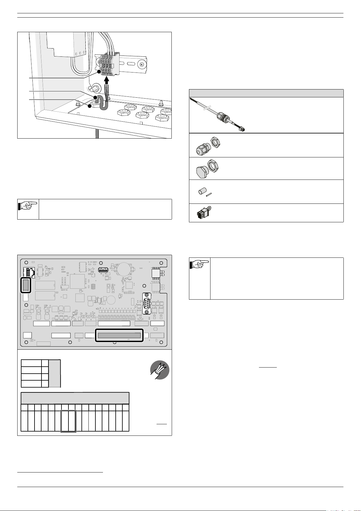
4.2.2 Connection cables11
Fig. 4.1
A Panel SlaveBoard cable11, incl. cable gland, termination
plug and heat shrink tubes
B SlaveBoard SlaveBoard cable12, incl. cable glands
A
[cable #1]
B
[cable #2]
Fig. 4.1 Connection cables
7. E.g. heat gun, cable stripping tool
8. The type of mounting material depends on the wall type
9. Number and type of cables depends on the selected options and control
equipment
10. For use in North America
11. The packages contain mounting material for the cables as well; refer to
paragraph 4.4.3 and 4.4.4
12. MDB only