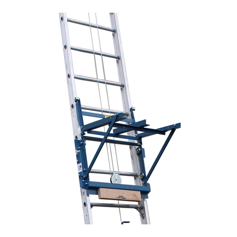
PMB Quick Access User manual

SAFETY
The general equipment used for erecting tower are as follows:
-Gloves -Ropes -Spirit Level
GENERAL EQUIPMENT
Always wear the Personal Protective Equipment (PPE) when erecting the access tower.
-Safety Helmet.
Wear a safety helmet in a construction site especially buildings where materials often fall from the upper level.
With safety helmet equipped, the chances of having injuries to the head can be minimized.
-Safety Footwear.
Wear appropriate footwear that completely covers the feet unless the type of work undertaken require otherwise.
-Safety Harness.
Wear safety harness when the maximum drop or free fall heights is 1.8m from ground to the working level.
The usage of safety harness with double lanyard is strongly recommended.
Always make sure the safety harness is hook to a safe and strong anchor support.
SAFE WORKING LOAD
The tower has a maximum total Safe Working Load (SWL) of 1000kg. This is the maximum load that can be
placed on the castors.
The safe working load at each level of platform is 275kg evenly distributed, regardless of whether one or two
platforms are installed. Therefore, even if two platforms are installed side by side, total cumulative load shall
not exceed 275kg distributed.
1
ERECTION MANUAL
USING 3T STEP
CORRECT
DOUBLE WIDTH LADDER SIDE
SAFE WORKING
LOAD 275 kgs
PER PLATFORM
SINGLE WIDTH LADDER SIDE

USAGE ADVISE
Erection
-Ensure that the instruction guide has been read and understood by anyone using the tower. If in doubt,
please contact your supplier.
-Check that all components are on site and that they are functioning correctly. Do not use damaged or
incompatible tower component. Make sure that you have the correct amount of components.
-Check if the ground on which the mobile access tower is to be erected and moved, is capable of
supporting the tower. Always take into account ground conditions. On soft ground a suitable base
must be provided.
-Tower must always be climbed from the inside during assembly and using the built in ladder provided
during use.
-Never lean a portable ladder against the tower, only use the built in ladder provided.
-Do not use the adjustable legs to gain extra height, they are for levelling the tower only.
-It is not permissible to attach bridging between a tower and a building.
-Do not use boxes or step ladders on the platform to gain additional height.
-It is forbidden to jump onto platforms.
-Towers used outdoors shall, whenever possible, be secured to a building or other structure.
-Tower shall only be moved manually and only on rm level ground which is free of obstacles. Normal
walking speed shall not be exceeded during relocation.
-For linking tower or special application always consult your supplier.
-It is not permissible to attach and use hoisting arrangement on towers unless specication provided
by design.
Lifting Equipment
-Tower component should be rmly secured by reliable lifting material (e.g. rope), employing a reliable
knot (e.g. clove hitch), to ensure safe fastening.
Stabilizers/Ballast
-Stabilizers and ballast weights shall always be tted when specied.
-Ballast is used at the base to stabilize towers against overturning. The quantity schedule shown the
recommended stabilization. In circumstances where there is restricted ground clearance for stabilizer,
contact your supplier for advice.
-If must be solid material (i.e. not water or loose sand) and should not be positioned to overload individual
legs. Ballast should be secured against accidental removal, and be supported on the lowest rung of the
bottom frame.
Dismantling tower
-Keep to the instructions in this guide.
-Never throw equipment from the tower.
-Always lower equipment down to ground level by rope or hand.
-Always report damaged equipment. Equipment should be maintained in a serviceable condition.
Wind Speed
-When wind exceeds Beaufort force 4, cease using the tower.
-If wind is expected to reach Beaufort force 6, tie tower to a rigid structure.
-If winds of Beaufort force 8 are forecasted, dismantle the tower or remove to shelter.
2
Force Peak mph Peak km/h Peak m/s Guidance
Moderate breeze-raises dust & loose paper
Strong breeze-dicult to use umbrella
Gale force-walking is dicult
8.1
13.9
20.8
29
50
74
18
31
48
4
6
8

MOVING TOWER
Before
-The tower should only be moved by manual eort, and only from the base.
-When moving the tower, beware of live electrical apparatus, particularly overhead, plus wires or moving
parts of machinery.
-No personnel or materials should be on the tower during movement.
-Make sure all castor wheels’ brakes are in release position.
-Caution should be exercised when wheeling a tower over rough, uneven or sloping ground, taking care
to unlock and lock castors. If stabilizers are tted, they should only be lifted suciently above the ground
to clear ground obstructions. The height of the tower, when being moved should not exceed 2.5 times the
minimum base dimensions, or 6 meters overall height.
After
-Relock castor and ensure that the tower is both vertically and horizontal aligned.
-Reposition stabilizers and ensure they have safe footing.
-Where necessary re-tie the towers to a rigid structure.
-Do not suspend mobile access towers without referring to your supplier.
-Atower must be kept in good working order. Any parts found to be faulty or missing should be
immediately replaced.
CARE & MAINTENANCE
-Equipment should kept clean, especially joints and moving parts.
-All working parts e.g. joints, threat should be lubricated lightly with oil.
-Do not let parts fall to the ground. Such abuse may reduce the structure integrity and
load capacity of the equipment.
-In the event of damage, the defective equipment must only be repaired by the qualied
personnel approved by the manufacturer
CHECK LIST
1. Inspect components before erecting the tower.
2. Ensure that the tower is upright.
3. Ensure all castors are locked.
4. Ensure all castors are rmly sited on the ground, not in hanging position
5. Ensure base plates are rmly sited on the ground. Sole plate needed when the tower is used on soft soil.
6. Ensure the tower is levelled by adjusting the adjustable leg.
7. Ensure Stabilizer are tted as specied in the assembly guide.
8. Ensure all the braces & platforms are properly installed.
9. Ensure the Handrails are tted in place.
10. Ensure Toe boards are correctly tted as specied in the assembly guide.
11. Ensure the Easy Access handrails are properly installed.*
12. Ensure the Couplers are locked rmly at the correct location.*
13. Ensure the Ballast is correctly in place.*
aa
a
aWALL
WALL
To position the tower in free
standing. Adjust the stabilizer
to form a square shape.
To position the tower against a
wall. Do not remove the
stabilizer, move parallel with
the wall.
To position the tower in a
corner. Remove the inside
stabilizer and place the
outside two parallel with the
wall.
STABILIZER BAR
Remarks: “*” - Applicable when item is used in the tower.
3
ASSEMBLY PROCESS
LOCK
UNLOCK
UNLOCK
LOCK

SPECIFIC PRODUCT INFORMATION
4
TABLE OF PARTS AND QUANTITIES
DOUBLE WIDTH LADDER SIDE/SINGLE WIDTH LADDER SIDE
PLATFORM HEIGHT (m)
WORKING HEIGHT (m)
TOWER HEIGHT (m)
TOWER WEIGHT IN kg
(2m PLATFORM)
TOWER WEIGHT IN kg
(2.5m PLATFORM)
TOWER WEIGHT IN kg
(3m PLATFORM)
2.36m
4.20m
3.70m
125kg
134kg
145kg
2.93m
4.70m
4.27m
134kg
154kg
166kg
3.50m
5.30m
4.84m
139kg
149kg
160kg
4.07m
5.90m
5.41m
149kg
159kg
172kg
4.64m
6.40m
5.98m
162kg
173kg
185kg
DW SW DW SW DW SW DW SW DW SW
104kg
112kg
119kg
115kg
132kg
140kg
119kg
126kg
134kg
127kg
134kg
143kg
140kg
147kg
158kg
4 RUNG LADDER
*DW-DOUBLE WIDTH LADDER SIDE
*SW-SINGLE WIDTH LADDER SIDE
4 RUNG NORMAL
3 RUNG LADDER
3 RUNG NORMAL
2 RUNG LADDER
2 RUNG NORMAL
HORIZONTAL BRACE
(2m,2.5m,3m)
DIAGONAL BRACE
(2m,2.5m,3m)
HATCH PLATFORM
(2m,2.5m,3m)
FIX PLATFORM
(2m,2.5m,3m)
STABILIZER BAR
TOE BOARD
ADJUSTABLE LEG
11212
11212
1
1
1
1
1
1
1
1
1
1
66666
46688
11111
11111
44444
11111
44444
(DW/SW)
(DW/SW)
(DW/SW)
(DW/SW)
(DW/SW)
(DW/SW)
*DW-DOUBLE WIDTH LADDER SIDE
*SW-SINGLE WIDTH LADDER SIDE
2.36m 2.93m 3.50m 4.07m 4.64mPLATFORM HEIGHT (m)

DOUBLE WIDTH ERECTION STEP
5
Step 1: Insert adjustable leg
with castor wheel into the
base of the ladder side frame.
Press down the braking
mechanism to lock the castor.
Step 2: Fit a horizontal brace
onto the vertical tube of the
frame, resting on the rst
horizontal tube. Ensure the
brace trigger is facing to the
outside of the tower.
Step 3: Fit the normal side
frame to the brace hook
resting on the opposite
horizontal rung. Fit the
second horizontal brace to
the horizontal tube as shown.
Level the base of tower using
spirit level and make
adjustment to the adjustable
leg until there is no
inclination from vertical.
Step 4: Place 4 rung frames &
secure them with frame clips.
Fit diagonal braces as
illustrated.
Step 5: Locate stabilizers to
each corners as shown and
ensure it touches the ground.
Step 6: Place hatch platform
as shown and ensure that the
hatch door opens outwards.
Step 7: Using Through The
Trapdoor (3T) method,
position yourself in a sitting
position on the hatch
platform as shown and t
4 horizontal braces, 2 on the
outside and 2 on the inside.
Step 8: Fit 4 rung frames as
illustrated.
Step 9: Place hatch platform
& xed platform and t
diagonal braces as shown.
Step 10: Using 3T method, t
4 horizontal braces as
illustrated.
NOTE: Repeat Step 6 to 8 until
desired platform height is
achieved and the follow
Step 9

DOUBLE WIDTH ERECTION STEP
6
Step 11: Fit diagonal braces
and toe board as shown.
Dismantling: - Reverse the steps of assembly.
Be sure to unlock the guardrail braces at the
end of the tower opposite the hatch platform
but leaving them in position. Then, return to
the seated position in the hatch platform
before unlocking the other ends and removing
the guardrail braces.
SINGLE WIDTH ERECTION STEP
Step 1: Insert adjustable leg
with castor wheel into the
base of the ladder side
frame. Press down the
braking mechanism to lock
the castor.
Step 2: Fit a horizontal brace
onto the vertical tube of the
frame, resting on the rst
horizontal tube. Ensure the
brace trigger is facing to the
outside of the tower.
Step 3: Fit the normal side
frame to the brace hook
resting on the opposite
horizontal rung. Fit the
second horizontal brace to
the horizontal tube as
shown. Level the base of
tower using spirit level and
make adjustment to the
adjustable leg until there is
no inclination from vertical.
Step 4: Place 4 rung frames &
secure them with frame clips.
Fit diagonal braces as
illustrated.
Step 5: Locate stabilizers to
each corners as shown and
ensure it touches the
ground.
Step 6: Place hatch platform
as shown.
Step 7: Using Through The
Trapdoor (3T) method,
position yourself in a sitting
position on the hatch
platform as shown and t
4 horizontal braces.
Step 8: Fit 4 rung frames as
illustrated.

7
Step 11: Fit diagonal braces
and toe board as shown.
Dismantling: - Reverse the steps of assembly.
Be sure to unlock the guardrail braces at the
end of the tower opposite the hatch platform
but leaving them in position. Then, return to
the seated position in the hatch platform before
unlocking the other ends and removing the
guardrail braces.
SINGLE WIDTH ERECTION STEP
Step 10: Using 3T method, t 4
horizontal braces as illustrated.
NOTE: Repeat Step 6 to 9 until
desired platform height is
achieved and then follow
step 10.
DISTRIBUTED BY: PMB QUICK ACCESS SDN BHD. (516692-V)
Lot 1797,Jalan Balakong,Bukit Belimbing,
43300 Seri Kembangan,Selangor D.E.
Malaysia
Tel : +603-8961 8355
Fax : +603-8961 1904
Email : sales@qaccess-scaolds.com
Website : www.qaccess-scaolds.com
SINGLE WIDTH LADDER SIDE
PART DETAIL
Horizontal Brace
Single Width
4 Rung Ladder
Side
Single Width
2 Rung Ladder
Side
Single Width
4 Rung Normal
Side
Hatch Platform
Single Width
2 Rung Normal
Side
Stabilizer Bar
Toe Board
Castor
Diagonal Brace
Step 9: Place hatch platform
and t diagonal braces as
shown.
DOUBLE WIDTH LADDER SIDE
PART DETAIL
Horizontal Brace
Double Width
4 Rung Ladder
Side
Stabilizer Bar
Double Width
2 Rung Ladder
Side
Castor
Diagonal Brace
Double Width
4 Rung Normal
Side
Double Width
2 Rung Normal
Side
Hatch Platform
Fix Platform
Toe Board
Table of contents
Popular Ladder manuals by other brands

MetalTech
MetalTech E-PWP7101AL Jobsite series instructions

Primal Vantage
Primal Vantage COMFORT ZONE HEH00582 Instruction and safety manual

Loft Centre
Loft Centre Caernarvon 400 Fitting instructions

Torklift
Torklift GlowStep Revolution owner's manual

KRAUSE
KRAUSE CORDA 916280 Instructions for assembly and use

Max
Max 57689 instruction manual