www
.polatrak.com
| 10851 Train Court, Houston, TX 77041 USA | Telephone: +1 (713) 983 7117 | Email: [email protected]© 2013 Deepwater Corrosion Services Inc. Specications subject to change without notice
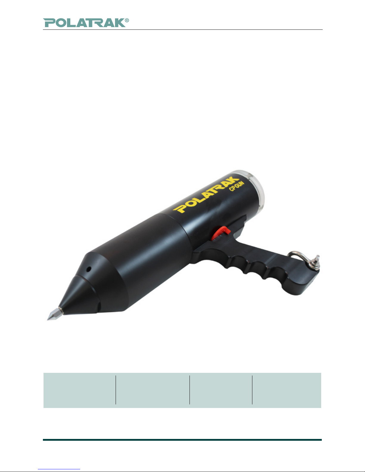
CP Gun operation manual
7Document 352-MN01-ENG, Rev. D
6.3 LED readout unit
Each reference electrode is connected to its own voltmeter LED readout. Both voltmeters are con-
tained in a pressure housing facing the rear of the CP Gun. Power is supplied to these voltmeters by
two standard, replaceable PP3 9-volt alkaline batteries. To access, see Section 8, maintenance.
6.4 Bulkhead connector
The probe tip and reference cells are connected to the voltmeters via a Seacon 3-pin bulkhead con-
nector. Before use, ensure that the connector is properly tightened. A thin layer of connector sealant
should be applied to the rubber shoulder of the male end, ensuring no sealant is applied to the cop-
per pin. Please refer to the MSDS before handling. All appropriate Personal Protective Equipment
(PPE) shall be worn including safety glasses and disposable gloves as a minimum.
6.5 Lens
The lens is made from a clear, acrylic material. The only reason to remove the lens is to replace the
9-volt batteries which power the LED readout unit.
6.6 Contact tips
Tips should be replaced once a stable potential reading can no longer be obtained.
Tips should not be sharpened with a le or hammered into a point.
To replace, remove the existing tip with a 7/16” (or 10mm) wrench; ats are best. Ensure that the new tip
is tight, but do not overtighten (max torque 50 inch-lbs).
6.7 On/o power switch
The CP Gun is powered on with the red rotational magnetic switch. With the switch in the rear (off)
position, rotate the switch to the on (forward) position. If the meter does not power on, check the
batteries (Section 8, maintenance). When the CP Gun is not in use, switching it off will extend the life
of the batteries, enabling use of the CP Gun throughout an entire survey season without the need to
replace the batteries.
CAUTION
The contact tip has been machined to a very sharp point to enable easier readings through
coatings. This point can also easily cut or poke through human skin. Please handle with care.
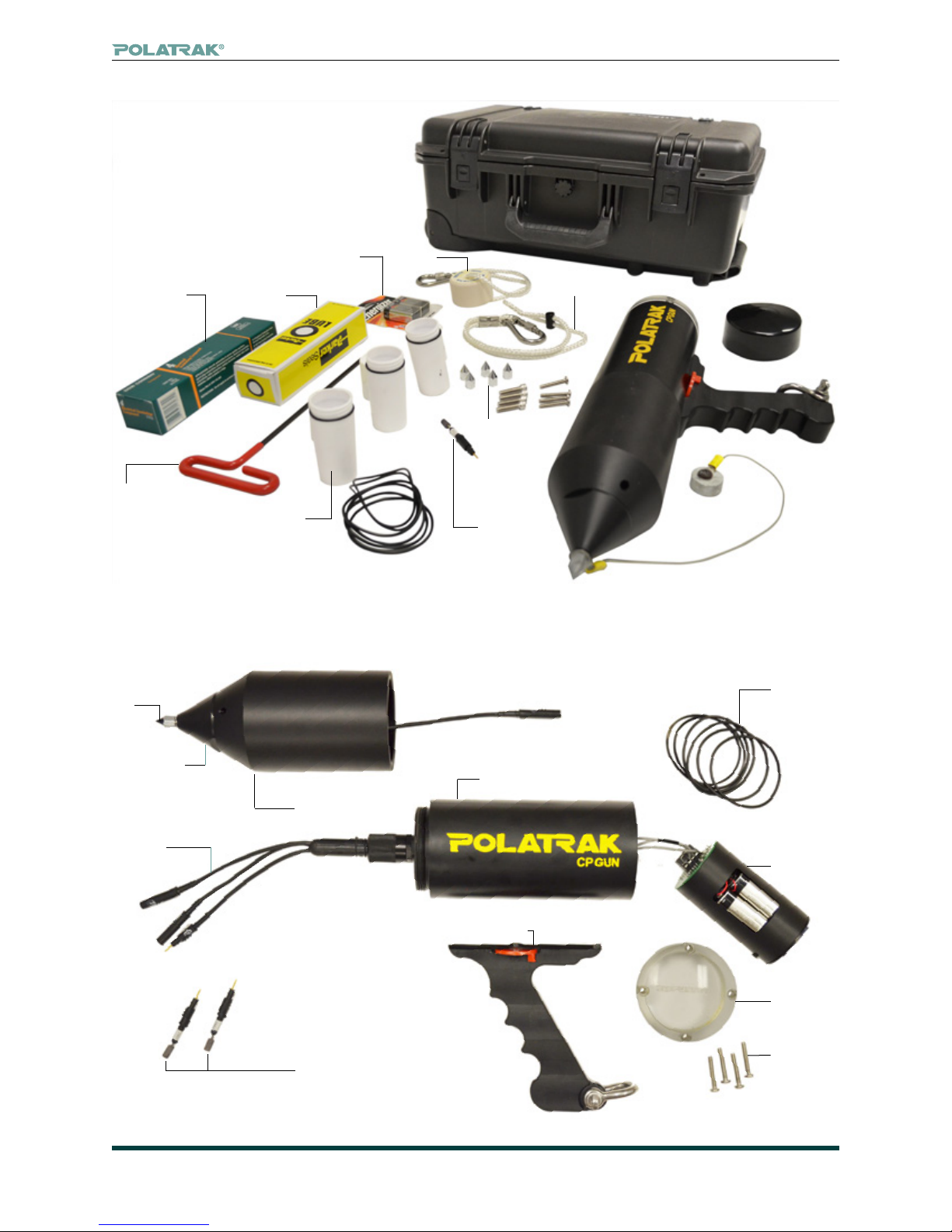
6.8 Spare parts and accessories
The CP Gun is shipped in a waterproof transit case and includes the following spares and accesso-
ries. Please contact your Deepwater representative to order additional spares if required.
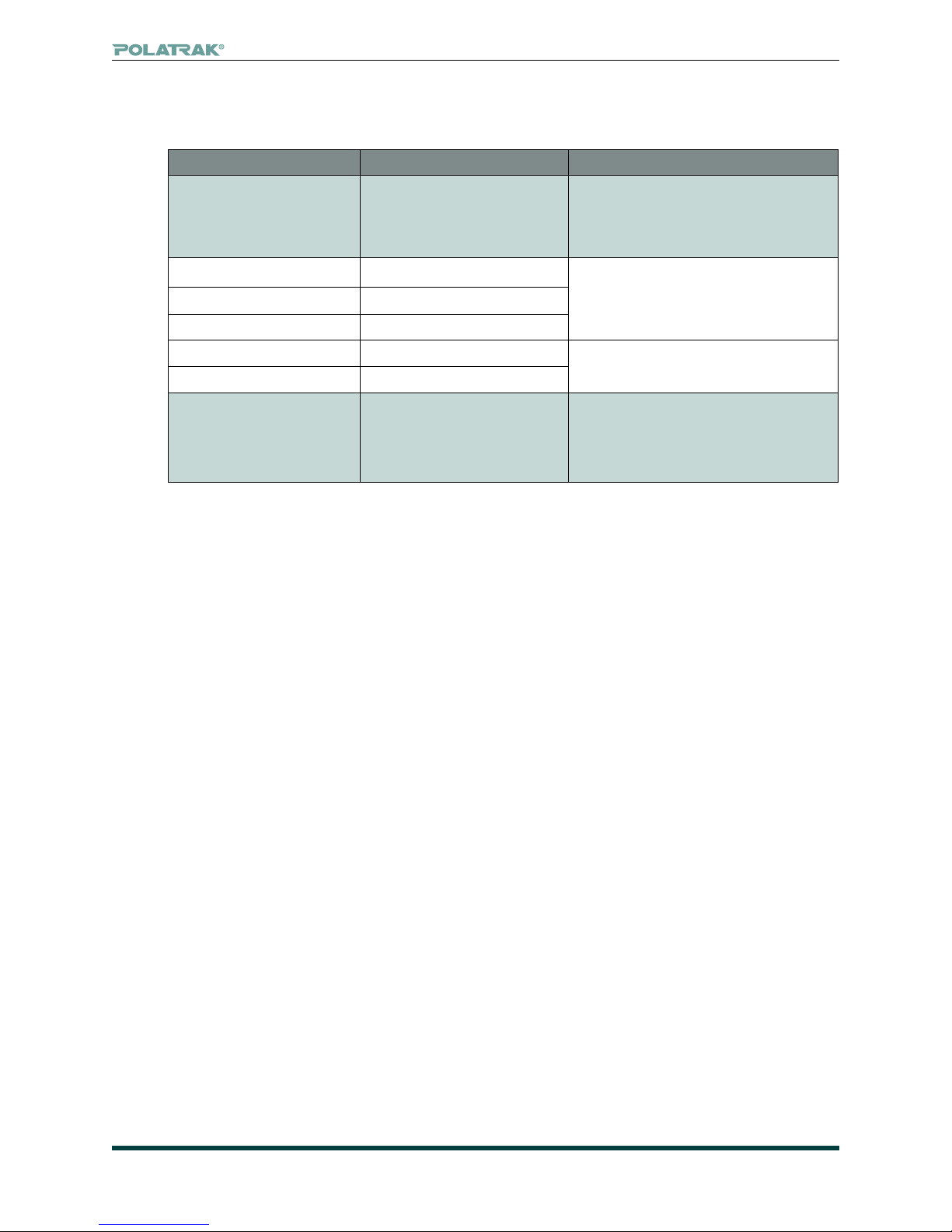
• Zinc calibration block (1) • Silicone connector lube (1)
• Contact tip (3) • Ag/AgCl electrode element (1)
• Lens retaining screw (4) • Lens back-up ring (2)
• O-Ring lube (1) • Lens O-ring (4)
7. Calibration test
(Please also refer to schematic in Fig. 6)
7.1 Bucket calibration check
7.1.1 Fill a clean, non-metallic bucket or container with enough seawater or simulated seawater to
completely submerge the probe unit. Ensure the bucket has been completely degreased and rinsed.
7.1.2 Place the probe in the bucket with the tip pointing up to ll body with seawater. The entire
probe, including the tip, must be immersed. Make sure there is no trapped air in the unit.
7.1.3 With a le or sandpaper, remove any layer of oxide from the zinc coupon before placing it in
the bucket.