CAUTION
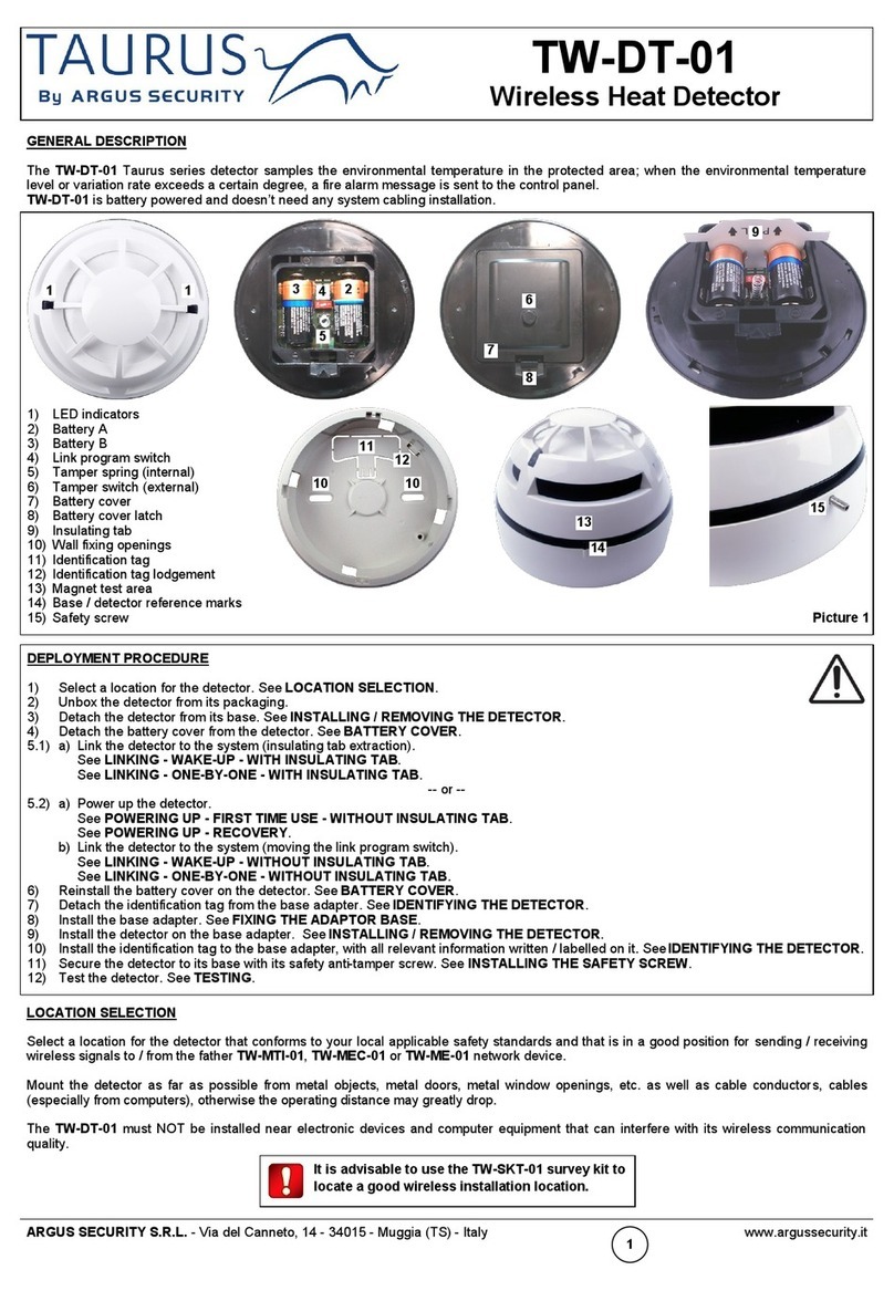
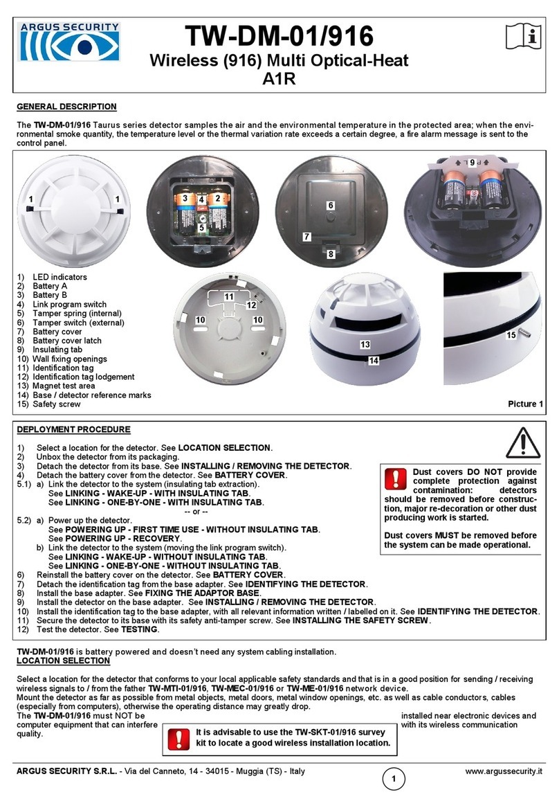
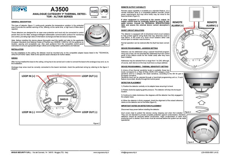
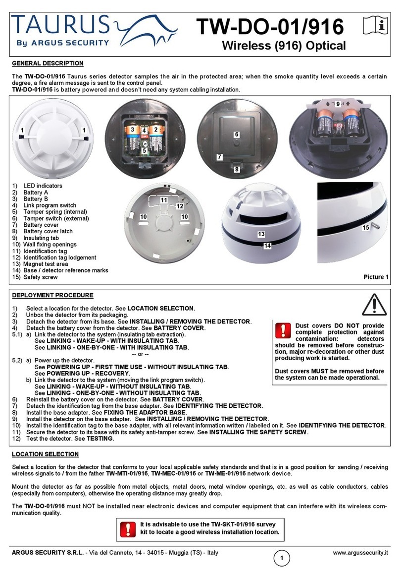
Dust covers help to protect the devices
during shipping and when first installed.
They are not intended to provide complete
protection against contamination, therefore,
detectors should be removed before con-
struction, major re-decoration or other dust
producing work is started. DUST COVERS
MUST BE REMOVED BEFORE THE SYSTEM
CAN BE MADE OPERATIONAL.
WARNING
Disconnect loop power before installing the
detector.
5. When the detector is firmly engaged verify the alignment
between the detector and the raised reference marks on the
base (figure 7).
6. After all detectors and other loop devices have been
installed, apply power to the loop in accordance with the
control panel’s installation instructions.
7. Test the detectors as described in the section headed
“TESTING”.
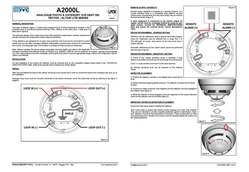
1. Position the detector centrally
on its mounting base (ensure it is
level).
2. Rotate clockwise applying
gentle pressure. The detector will
drop into its keyed location.
3. Press more firmly to win the
force of the contacts.
4. Continue to rotate clockwise a
few degrees until the detector has
fully engaged in the mounting
base.
Alignment between the detector and
the base’s reference raised marks.
Figure 7 - The correctly installed detector.
Magnet test position (model TMD-01).
WARNINGS AND LIMITATIONS
Our devices use high quality electronic components and plastic materials that are highly resistant to
environmental deterioration. However, after 10 years of continuous operation, it is advisable to replace the
devices in order to minimize the risk of reduced performance caused by external factors. Ensure that this
device is only used with compatible control panels. Detection systems must be checked, serviced and
maintained on a regular basis to confirm correct operation.
Smoke sensors may respond differently to various kinds of smoke particles, thus application advice
should be sought for special risks. Sensors cannot respond correctly if barriers exist between them and
the fire location and may be affected by special environmental conditions.
Refer to and follow national codes of practice and other internationally recognized fire engineering stand-
ards.
Appropriate risk assessment should be carried out initially to determine correct design criteria and updat-
ed periodically.
WARRANTY
All devices are supplied with the benefit of a limited 3 year warranty relating to faulty materials or manu-
facturing defects, effective from the production date indicated on each product.
This warranty is invalidated by mechanical or electrical damage caused in the field by incorrect handling
or usage.
Product must be returned via your authorized supplier for repair or replacement together with full infor-
mation on any problem identified.
Full details on our warranty and product’s returns policy can be obtained upon request.
ARGUS SECURITY S.R.L.
Via del Canneto, 14
34015 Muggia (TS)
Italy
09
0832-CPD-1067
EN 54-7
Point type smoke detector
(optical)
EN 54-5
Point type heat detector
Class A1R
EN 54-17:2005
Short circuit isolator
CEA 4021
V200
Technical data: see docu-
ment
TDS-V200X held by the
manufacturer.
0832
ARGUS SECURITY S.R.L.
- Via del Canneto, 14 - 34015 - Muggia (TS) - Italy www.argussecurity.it [email protected] SPNK-754431-052 (v2.4) ATTENZIONE
I copri-polvere proteggono i dispositivi du-
rante la spedizione e la prima installazione.
Non assicurano una protezione totale contro
agenti contaminanti: i sensori dovrebbero
essere rimossi prima di iniziare lavori di
costruzione, manutenzione, o, in generale,
lavori che producono polvere. I COPRI-
POLVERE DEVONO ESSERE RIMOSSI PRIMA
CHE IL SISTEMA DIVENTI FUNZIONANTE ED
OPERATIVO.
ATTENZIONE
Disconnettere l’alimentazione del loop prima
di installare il sensore.
5. Quando il sensore è agganciato in modo sicuro, effettuare la verifica di
allineamento tra il sensore ed i riferimenti rialzati sulla base (figura 7).
6. Dopo che i sensori e gli altri dispositivi del loop sono stati installati, ali-
mentare il loop in conformità alle istruzioni operative della centrale.
7. Testare i sensori come descritto nel paragrafo “COLLAUDO”.
1. Posizionare il sensore central-
mente sulla base di montaggio
(assicurarsi che sia a livello).
2. Ruotare il sensore in senso
orario usando una leggera pressio-
ne. Il sensore si innesterà nella
base.
4. Continuare a ruotare di qualche
grado in senso orario finché il
sensore non si aggancia salda-
mente alla base di montaggio.
3. Applicare una maggiore pressio-
ne per controbilanciare la forza dei
contatti.
Allineamento tra i riferimenti rialzati
del sensore e della base.
Figura 7 - Il sensore correttamente installato.
Posizione del magnete di test (modello TMD-01).
AVVERTENZE E LIMITAZIONI
I nostri dispositivi sono costruiti con componenti elettronici di alta qualità e materiali plastici molto resi-
stenti al deterioramento ambientale. Ciononostante, dopo 10 anni di operatività, si consiglia di sostituire i
dispositivi al fine di minimizzare il rischio di una ridotta prestazione derivata da fattori esterni. Ci si assicuri
che questo dispositivo sia usato soltanto con centrali compatibili. I sistemi di rilevamento devono essere
controllati e sottoposti regolarmente a manutenzione per ratificarne la corretta operatività.
I sensori di fumo possono rispondere differentemente a diversi tipi di particelle di fumo, quindi, per rischi
particolari, chiedere consulenza riguardo alla compatibilità di questo prodotto al proprio fornitore.
I sensori potrebbero non rispondere adeguatamente se tra gli stessi ed il luogo dell’incendio esistono
barriere; inoltre, particolari condizioni ambientali possono influire sulla loro risposta.
Fare riferimento ed applicare normative nazionali ed altri standard di sicurezza antincendio riconosciuti
internazionalmente.
Un’adeguata valutazione dei rischi dovrebbe essere effettuata inizialmente per definire i criteri di progetta-
zione ed aggiornata periodicamente.
GARANZIA
Tutti i dispositivi sono garantiti fino a 3 anni, limitatamente a materiali difettosi o difetti di fabbricazione, a
decorrere dalla data di produzione indicata su ogni prodotto.
Questa garanzia non copre danni meccanici od elettrici causati in campo da un uso scorretto ed inade-
guato.
Il prodotto deve essere ritornato, tramite il proprio fornitore, per riparazione o sostituzione, assieme ad
una descrizione completa di qualsiasi problema riscontrato. Tutti i dettegli sulla garanzia e sulla modalità
di ritorno dei prodotti possono essere ottenuti su richiesta.
ARGUS SECURITY S.R.L.
Via del Canneto, 14
34015 Muggia (TS)
Italy
09
0832-CPD-1067
EN 54-7
Point type smoke detector
(optical)
EN 54-5
Point type heat detector
Class A1R
EN 54-17:2005
Short circuit isolator
CEA 4021
V200
Dati tecnici: consultare il
documento TDS-V200X in
possesso del costruttore.
0832
SETTING THE ADDRESS
Detectors can be addressed using a special hand-held programming unit or they can be auto-addressed by the control panel after
they have been installed (the implementation of the auto-addressing feature depends on the control panel’s manufacturer).
Addresses may be selected from a range from 1 to 240, although, of course, each device on the loop must have a unique address.
SENSITIVITY SETTINGS
A choice of four sensitivity levels are available which can be set via the hand-held programming unit or by panel selection (if provid-
ed). Level 1 is most sensitive, level 4 is least sensitive.
ANTI-TAMPER MECHANICAL BLOCK FEATURE
The detector may be locked onto its base by removing
the small plastic element on the base’s detector block-
ing hook by using a suitable tool (e.g. a small screw-
driver) inserted through the access hole on the side of
the mounting base (figure 6).
To remove the detector from the base, if mechanically
blocked, insert a suitable tool (e.g. a small screwdriver)
through the access hole on the side of the mounting
base (figure 6).
TAMPER DETECTION
A fault condition is triggered on the Vega protocol compatible control panel if a detector, on the loop, is removed from its mounting
base.
TESTING
Detectors should be tested after installation and during periodic maintenance visits (it is recommended each device should be tested
at least once per year). When the system has been reset, allow, after each test, at least one minute for power stabilisation before the
next test. Detectors can be tested as follows:
Magnet test
Position the magnet (model TMD-01, optional) next to the detector, between the two raised marks on the base (figure 7). The magnet
test simulates smoke in the optical chamber and heat on the thermistor, and verifies the function of all electronic circuits of the detec-
tor and its communication with the control panel. The detector should trigger an alarm message to the control panel, and, successive-
ly, the detector’s red LED should be activated by the control panel itself.
Aerosol (simulated smoke) test
For this test only use test aerosols from an approved manufacturer, in accordance with their application instructions, in order to
prevent contamination or possible damage to the detector. We suggest to spray the aerosol into the detector by using a recommend-
ed applicator. The detector should trigger an alarm message to the control panel, and, successively, the detector’s red LED should be
activated by the control panel itself.
Heat test
Use a hair dryer of 1000-1500 W or an heat tool from an approved manufacturer. Direct the heat towards the sensor from its side.
Hold the heat source at about 15 cm away from the sensor in order to prevent damage to its cover during testing.
The detector should trigger an alarm message to the control panel, and, successively, the detector’s red LED should be activated
by the control panel itself.
If the detector does not respond to the tests correctly it may be necessary to clean it: in this case follow the instructions indicated in
the “MAINTENANCE” paragraph.
If testing fails again after maintenance then replace the detector with a new one and return the faulty one for servicing.
MAINTENANCE
Before starting any maintenance work, isolate and disable the system in order to avoid accidental and unwanted alarm or fault condi-
tions. Remove the detector from its mounting base to allow inspection in good light at ground level. Inspect the smoke entry ports
around the detector and the thermistor area; use a small, soft bristle brush to dislodge any evident contaminants such as insects,
spider webs, hairs, etc. Use a small vacuum tube or clean, dry and compressed air to suck up or blow away any remaining small
particles from the smoke entry screen area and the thermistor area.
Wipe the exterior housing of the detector with a clean, damp, lint free cloth to remove any surface film that can later attract airborne
contaminants. Use the hand-held programming unit to read the pollution percentage of the chamber; please, refer to the program-
ming unit instruction manual. After all detectors have been inspected, repositioned on their mounting bases and power has been re-
applied, check correct operation as described under the “TESTING” paragraph.
Figure 6 - The anti-tamper block and its handling.
IMPOSTARE L’INDIRIZZO ANALOGICO
I sensori possono essere indirizzati usando uno speciale programmatore manuale; in alternativa possono essere indirizzati diretta-
mente dalla centrale in seguito all’avvenuta installazione, sempreché la funzione di indirizzamento automatico sia stata implementata
dal costruttore della centrale.
Gli indirizzi selezionabili spaziano da un campo di valori che va da 1 a 240, anche se, ovviamente, ogni dispositivo su un singolo loop
deve avere un indirizzo univoco.
IMPOSTAZIONE DELLA SENSIBILITA’
Sono disponibili quattro livelli di sensibilità impostabili tramite programmatore o direttamente da centrale (sempre che questa funzio-
ne sia stata implementata dal costruttore). Il livello 1 è il più sensibile mentre il livello 4 è il meno sensibile.
BLOCCO MECCANICO ANTI-EFFRAZIONE
Il sensore può essere bloccato al suo supporto rimuo-
vendo il rialzo di plastica sul gancio di bloccaggio della
base; per fare ciò usare uno strumento adatto (es. un
piccolo cacciavite) inserito attraverso il foro di accesso
laterale della base (figura 6).
Per rimuovere il sensore dalla base, se meccanicamen-
te bloccato, usare uno strumento adatto (es. un piccolo
cacciavite) inserito attraverso il foro di accesso laterale
della base (figura 6).
RILEVAZIONE DI EFFRAZIONE
La centrale analogica segnala una condizione di guasto se un sensore, sul loop, viene rimosso dalla sua base.
COLLAUDO
I sensori dovrebbero essere collaudati dopo l’installazione ed in seguito periodicamente (si consiglia di collaudare ogni dispositivo
almeno una volta l’anno). Quando il sistema è stato ripristinato (reset), far passare, dopo ogni prova, almeno un minuto di stabilizza-
zione prima di passare al prossimo test. Le prove da effettuare sui sensori sono le seguenti:
Test magnete
Posizionare il magnete (modello TMD-01, opzionale) molto vicino al sensore, tra i due riferimenti rialzati della base (figura 7). Questo
test simula fumo nella camera ottica e calore sul termistore, verifica il funzionamento dell’elettronica del sensore e la sua comunica-
zione con la centrale. Il sensore dovrebbe mandare un messaggio di allarme alla centrale; successivamente il LED rosso dovrebbe
essere attivato direttamente dalla centrale stessa.
Test aerosol (fumo simulato)
Per questo test usare solamente aerosol da fornitori approvati, in conformità con le loro istruzioni operative, per evitare di contamina-
re od eventualmente danneggiare il sensore stesso. Si suggerisce di spruzzare l’aerosol usando un applicatore raccomandato.
Il sensore dovrebbe mandare un messaggio di allarme alla centrale, e, successivamente, il LED rosso del sensore dovrebbe essere
acceso dalla centrale stessa.
Test col calore
Usare un asciugacapelli da 1000-1500 W od un dispositivo di test per rilevatori termici da un fornitore approvato. Dirigere il calore
sul lato del sensore, tenendo la sorgente di calore lontana almeno 15 cm per evitare che la plastica esterna si danneggi durante il
test.
Il sensore dovrebbe mandare un messaggio di allarme alla centrale, e, successivamente, il LED rosso del sensore dovrebbe
essere acceso dalla centrale stessa.
Se il sensore non risponde al test correttamente può essere necessario pulirlo: in questo caso eseguire le istruzioni riportate nel
paragrafo “MANUTENZIONE”.
Se il test, dopo avere effettuato la manutenzione, fallisce di nuovo, sostituire il dispositivo con un altro e mandarlo in
assistenza.
MANUTENZIONE
Prima di iniziare qualsiasi lavoro di manutenzione, disabilitare il sistema allo scopo di evitare l’innescarsi di condizioni di allarme e di
guasto indesiderate. Rimuovere il sensore dalla sua base al fine di effettuare un’ispezione con una buona illuminazione ed a livello
del suolo. Controllare le entrate per il fumo attorno al rilevatore e l’area del termistore ed usare una piccola spazzola con setole
morbide per rimuovere gli agenti contaminanti evidenti come insetti, ragnatele, capelli, ecc.
Usare un piccolo aspiratore od aria compressa pulita e secca per aspirare o soffiare via le piccole particelle di contaminanti rimanenti
dall’area di entrata del fumo e del termistore. Pulire la superficie esterna del sensore con un panno pulito, umido e senza filacci per
rimuovere qualsiasi patina di impurità superficiale che potrebbe, in futuro, attrarre eventuali agenti contaminanti nell’aria. Usare il
programmatore manuale al fine di leggere la percentuale di contaminazione della camera ottica; fare riferimento al manuale operativo
del programmatore.
Dopo che tutti i sensori sono stati ispezionati, riposizionati sulle loro basi e l’alimentazione è stata ripristinata, verificarne il corretto
funzionamento come descritto nel paragrafo “COLLAUDO”.
Figura 6 - Il gancio anti-effrazione e come
sbloccarlo.
