Politec Sandor S Series Guide

1
Installation
And commissioning
manual
Series S
Double Beam

2
Index
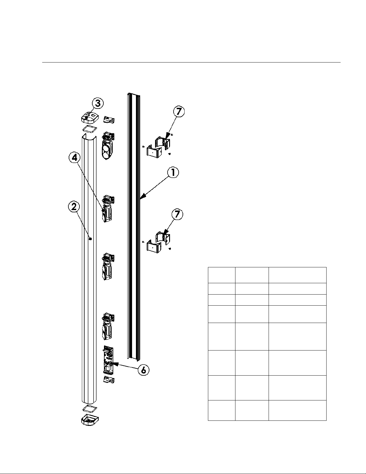
Main components list Pag. 3
Installation reccomendations Pag. 4
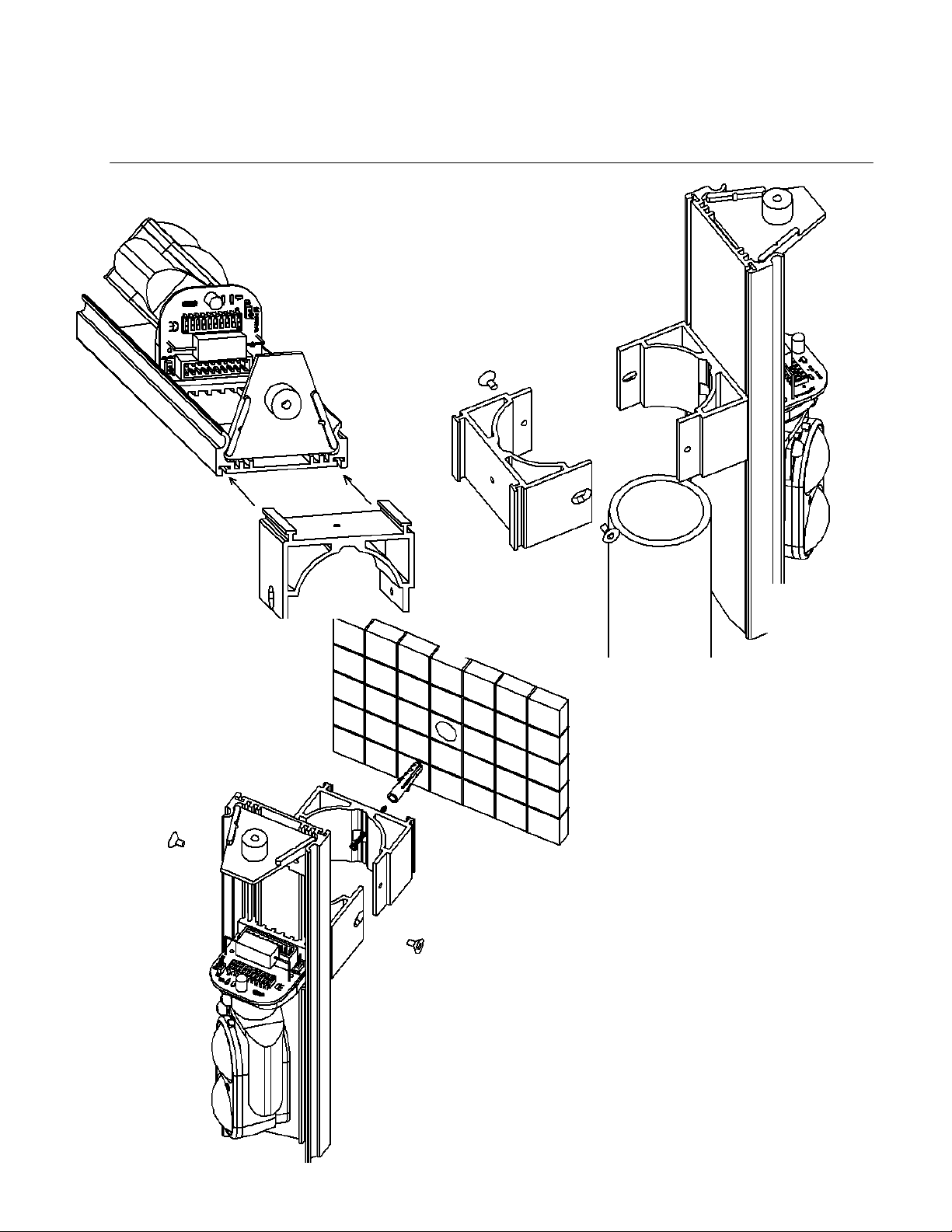
Mounting the bracket Pag. 5
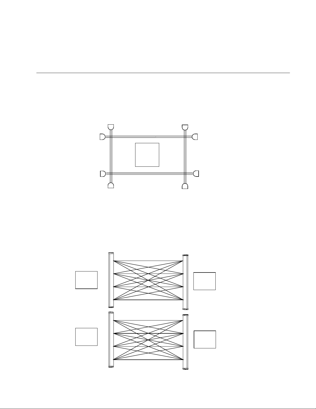
Installation example Pag. 6
Positioning the beam with respect to others in the perimeter Pag. 7
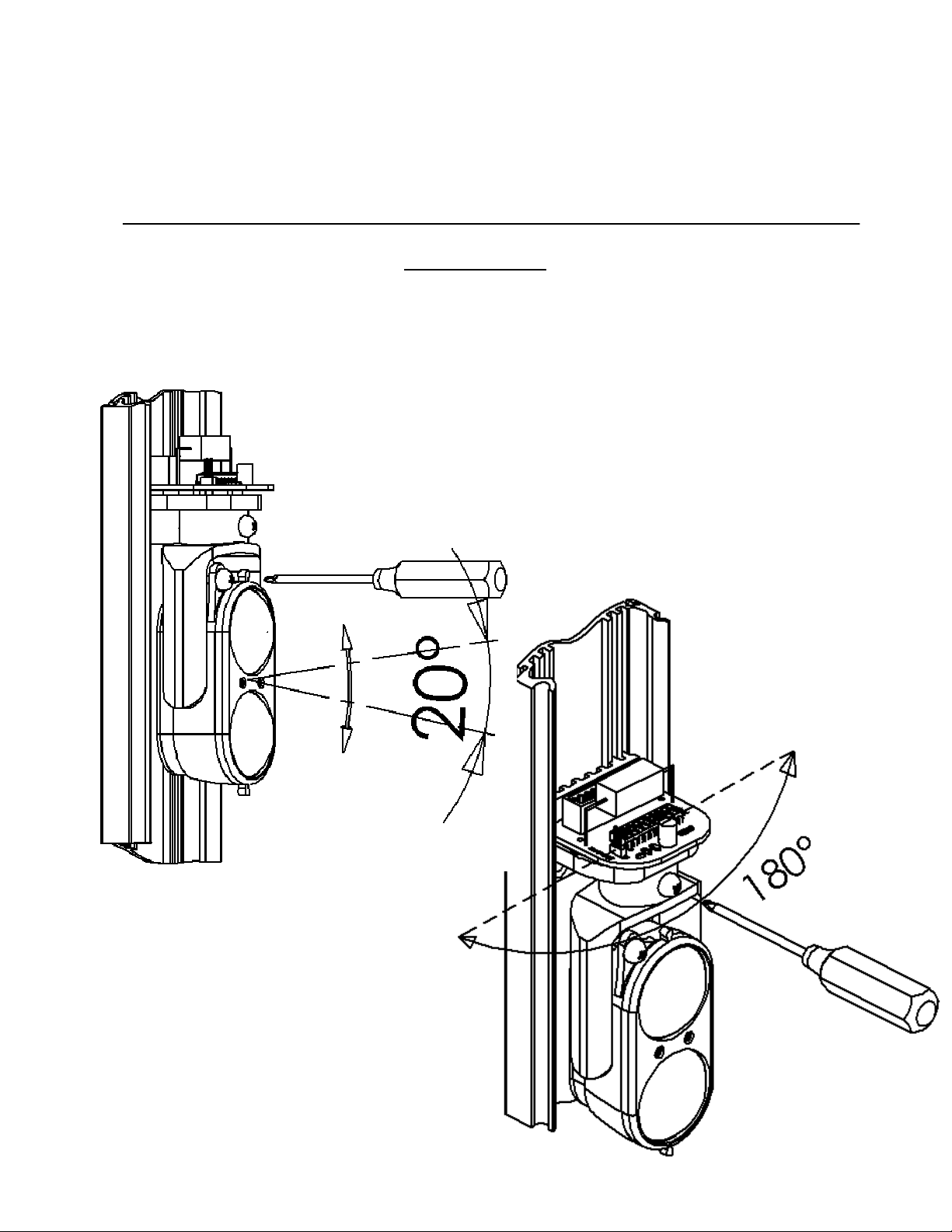
Alignment Pag. 8
Vertical alignment of the mirror Pag. 8
Horizontal alignment of the mirror Pag. 8
Cabling and terminal connections Pag. 9
Transmitters main P.C.B. Pag. 9
Receivers main P.C.B. Pag. 10
Set-up using the test point on the main Transmitter P.C.B. Pag. 11
Set-up using the test point on the main receiver P.C.B. Pag. 14
Set up examples Pag. 15
Alignment checking Pag. 16
Setting and programming Pag. 17
Functional description of the led’s Pag. 17
Operational characteristics and Link setting Pag. 18
Technical specifications Pag. 19

3
Main component list
N°
Parte Q.ty Description
1 1 Mounting plate
2 1 Front cover
3 2 Front cover
top/end caps
4 2 Trasmitter /
receiver optic
5 1 Flat cable
6 1 Receiver /
trasmitter P.C.B.
7 4 Bracket

4
Installation reccomendations
• Verify that the beam tower is fully watertight once the cover and end caps have
been correctly filled at the end of the installation.
• Use the cable glands supplied on the tower for all cabling must pass through the
lower end cap using the cable glands supplied.
• Avoid any type of obstruction between the transmitter and receiver.
• Avoid installing the receivers beams in a position where direct sunlight, at the same
angle as the receivers beams, can enter directly into optics especially at sunset and
sunrise
• Do not install multiple beams where the transmitter beam can interfere with other
receiver beams. It is always better place either transmitter or receivers back to
back.
• Do not use switched power supplies which can induce noise on the power supply
voltage which can in turn be amplified by the optical sync electronics creating
unwanted problems.

5
Mounting the bracket
Insert the bracket back to
mounting plate
Wall mounting
Diameter 50 mm
Pole
mounting

6
Installation example
Pole
mounting Wall
mounting Wall mounting
With interposed
brakets

7
Positioning beam with respect to others in the
perimeter
Rx
Tx
Tx
Rx
Rx
Tx
Tx
Rx
Tx
Rx
Tx
Rx

8
Alignment
Initial alignment
Once beam columns have been correctly installed point the transmitter optics towards its
corresponding receiver and vice versa, repeat for all the beam pairs.
This is achieved by manually positioning the lens holder horizontally and vertically using
one of the two screws (which ever is more convenient) to be found above the lens.
Vertical alignment
Horizontal alignment

9
Cabling and terminal connections
TRANSMITTERS
MAIN P.C.B.
Always use screened multicore cable for alarm output, power supply 12
dc, relè output, And, Tamper connection
Always use separate power supply 24 V ac cable of proper diameter

10
Cabling and terminal connections
RECEIVERS
MAIN P.C.B.

11
Set-up using the test point on the main
Transmitter P.C.B.
It is necessary to put the transmitter PBC “A” into the test mode in order to complete the
alignment.
Phase 1 Insert into ON position the TEST P SET Link on the main transmitter PCB
Phase 2 Move in OFF the dip switch corresponding to the beam to be aligned.
Phase 3 Connect the Voltmeter, using the cable supplied, to the corresponding receiver
test point, move the transmitter optics slightly in both axes (horizontal and
vertical) until the maximum voltage is obtained. Repeat with receiver optics.
Phase 4 Once the alignement is obtained replace the dip switch in ON
Phase 5 Repeat the above procedure for all beam pairs after which reinsert, into OFF
position the TEST P SET Link.
Transmitters main
PC.B
Phase 1 and 5
Phase 2 and 4

12
Transmitters

13
Receivers

14
Use the cable
supplied
Set-up using the test point on the main
receiver P.C.B.
It is necessary to put the transmitter PBC “A” into the test mode in order to complete the
alignment.
Phase 1 Insert into ON position the TEST P SET Link on the main transmitter PCB
Phase 2 Move in OFF the dip switch corresponding to the beam to be aligned.
Phase 3 Connect the Voltmeter, using the cable supplied, to the corresponding receiver
test point, move the transmitter optics slightly in both axes (horizontal and
vertical) until the maximum voltage is obtained. Repeat with receiver optics.
Phase 4 Once the alignement is obtained replace the dip switch in ON
Phase 5 Repeat the above procedure for all beam pairs after which reinsert, into OFF
position the TEST P SET Link.
Reading
without Signal 0,20V 0,40V
Reading with
signal
From 3
to 4V
From 6
to 7V
Verifing on the tester at the
Test Point RX
In alignement always
obtain the maximum
value
Phase 3

15
Set up examples
Tx 1
Tx 2
Tx 3
Tx 4
Jumper TEST POINT SET (see Fig at page.8)
on Transmitters main P.C.B. Tx into ON Position
Reinsert the Jumper TEST POINT SET
into
OFF position at the end of set up
Replace in ON after each set up
Move the dip switch 1 in OFF
Move the dip switch 2 in OFF
Replace in ON after each set up
Move the dip switch 3 in OFF
Replace in ON after each set up
Move the dip switch 4 in OFF
Replace in ON after each set up

16
Alignment checking
(suggested for short distance)
Tx 1
Tx 2
Tx 3
Tx 4
Smalll differences must be are noted among
the voltage readed from the tester for each
receipters.
If not make small vertical adju
stments of the
receipter involved.

17
Setting and Programming
FUNCTIONAL DESCRIPTION OF THE LED’S
The five LED’s on the SANDOR QUAD RX P.C.B give system status indication.
Placing the appropriate Link into the ON position can enable these LEDs.
It is good practice, to increase security, to place the Link into the OFF position, once the
beams have been set-up.
LED MASK Indicates BEAM MASKING. The MASK will light or flash if an extraneous
modulated IR source greater than that of the transmitter is detected by
receiver electronics. If the ANTIMASK Link is in the ON position an alarm
condition will be generated when such IR source is detected.
N.B.: the LED should be OFF in the quiescent condition. If it is either on or
flashing check the TX beam set-up.
LED DETECT Detect beam interruption. The DETECT LED will light each time a beam
on the SANDOR is interrupted. This is independent to the alarm relay
opening, which is also dependent on how the target SPEED criterion has
been set.
N.B. The LED should be OFF in the quiescent condition.
The LED will flash if one or more, but not all the TX signals are absent at
the RX (giving beam blocked or beam misaligned information).
The led will light if all Tx are absent or if one or more Rx are blocked or
misagniled.
LED ALM Alarm confirmation LED. Normally OFF indicates an alarm when lit. The
alarm condition on the SANDOR is dependent how the Links are set on the
Rx P.C.B., and the delay (between 50 mSec and 1 Sec) set on the target
SPEED trim pot.
LED HTR Confirm that the system heaters are ON. The QUAD and HEX versions
of the SANDOR are equipped with automatic electronic thermostatically
controlled heaters, which guarantee an operating temperature within the
housing of between 17°C and 22°C in cold weather.
The Led is normally OFF and ON when the heaters are ON.
POWER Power ON LED. The POWER on LED is always ON and indicates that the
that the supply voltage to PCB is correct.

18
Receivers
PCB
Transmitters
PCB
OPERATIONAL CHARACTERISTICS AND LINK SETTING
The SANDOR QUAD Rx can be set-up in a number of different configurations that are
selected using the appropriate Links.
BEAM (factory setting) Putting the Link in the ON position enables the relative
beam, starting with beam No. 3 (For example) E.G. if all 6 beams are used
Links, 3,4,5 & 6 will be in the ON position.
BEAM Putting one Link in the ON position enables the correspondent number of
Transmitter optics.
Only one Link shall be connected on the BEAM Links.
(For example: 4 beam link will be only in position 4)
AND 1-2 The first two beams will be put into “AND” with this Link in the ON position.
In this configuration the lower two beams have to be interrupted
simultaneously in order to create an alarm condition. The other beams will
continue to operate singly.
AND In the ON position at least two beams must be interrupted in order than an
alarm condition is created.
This feature can also be enabled remotely via the appropriate command on
terminal block (AND with + 12 v dc).
SPEED Set the beam interruption time (50 msec 500 msec) and the crossing speed
detectable accordingly. Slower setting reduce sensitivity .
A long interruption time will detect intruders but let pass through cats, birds
can occasionally interrupt the beam.
ANTIMASK In the ON position a detected masking signal will create an alarm condition
(See the MASK LED above).
PT1 Set the sensitivity of antimasking device (factory setting).
Setting on site can be obtained rotating clockwise the device until the led
MASK is ON, then rotate anticlockwise 10 times at 360°.
LEDS In the ON position all the LEDs will indicate as described above.
N.A. N.C. The Link chance the relay output from normally Open (NO) to normally Close
(NC).
TAMPER Connector for tamper switch.

19
Technical specifications
MODELLI DUAL QUAD ESA
Maximum range 850 m
Max useable range internal 240 m
Max useable range external 80 m
Minimum range 4 m 8 m
Tower height 35 cm 1 m 1,5 m – 2,0 m
Synchronization Optical
Total number of beams 4 Crossed 16 Crossed 36 Crossed
Power requirements 12Vdc
Power consumption for tower Tx / Rx 40
mA
Tx / Rx 60 mA Tx / Rx 80 mA
heater 12W 24Vac
20W 24Vac
termostatically
controlled
30W 24Vac
termostatically
controlled
OPERATING TEMPERATURE –25°/ +65°
VERTICAL ALIGNMENT ANGLE 20°
HORIZONTAL ALIGNMENT ANGLE 180°
AND/OR DETECTION OPTION REMOTE AND CONTROL
AUTOMATIC ANTI-BLANKING SYSTEM (SHUTNTABLE)
ADJUSTABLE DETECTION SPEED 50/500 ms
ALARM OUTPUT RELAY NO/NC SELECTABLE
NC TAMPER OUTPUT
SHUNTABLE LED’S INDICATING:
ON-BLANKED-ALARM-HEATING
PULSED INFRA-RED SIGNAL
WAVELENGHT 950 mm
PROTECTION RATING IP 54
WALL MOUNTING
POLE MOUNT ADAPTER
2 YEAR GUARANTEE

20
POLITEC s.r.l.
POLITEC s.r.l. – Via Adda 66/68 – 20040 – Bellusco (Mi – Italy
Tel. + 39.039.6883019 r.a. – fax + 39.039.6200471
www.politecsrl.it
R 1.0
This manual suits for next models
3
Table of contents
Other Politec Lighting Equipment manuals
Popular Lighting Equipment manuals by other brands

Perel
Perel LEDA7001NW-BM user manual

ambiance
ambiance LV-054 Installation and safety instructions

Ansult
Ansult 425-439 operating instructions

Vision & Control
Vision & Control SLE-150-B460-P-SL Instructions for use

Sensio
Sensio Linia SE980320 manual

HEPER
HEPER REGIO 3 Installation & maintenance instructions